Week 5 assignment: 3D scanning and printing
Summary
This week we had to test the design rules for the 3D printers we have at the fablab and 3D print a small object that could not be easily made subtractively. Additionally, do a 3d scan an object and document the process. At the Fablab at the University of Lima we have several 3D printers and I was able to observe the difference between the printing qualities.
Process
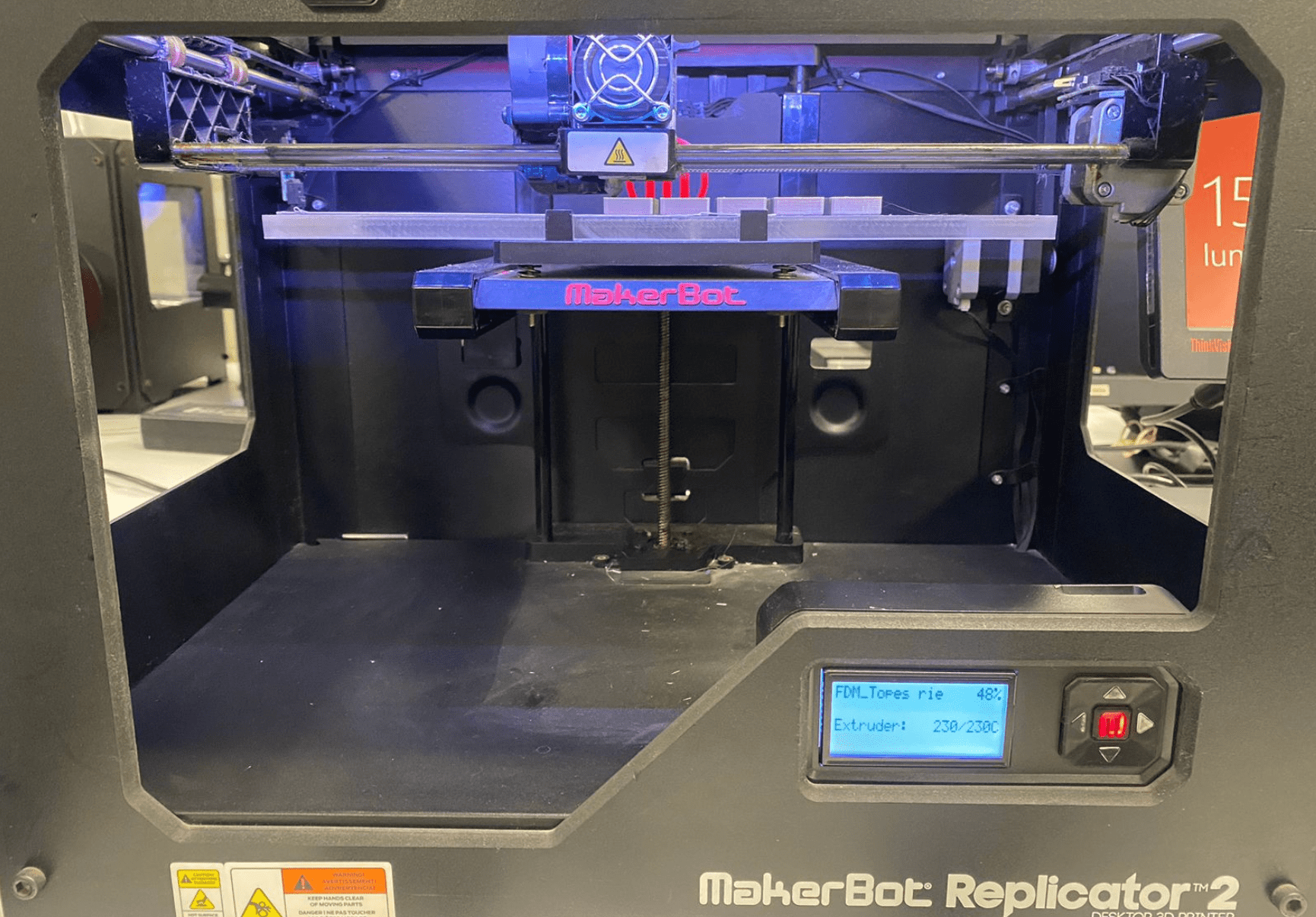
The 3d printer used was the Replicator 2:
In order to print objects and designs on a 3D printer, we must first design it in some CAD software. The object I chose to print was a turbine, fulfilling the objective of not being able to be manufactured following a subtractive process.
Subtractive manufacturing, such as milling, involves removing material from a solid block to create a desired shape. Certain designs, especially those with complex geometries (like my turbine design), internal structures, or intricate details, may be challenging or impossible to produce using subtractive methods.
In my case, my design has complex curved surfaces that will be difficult to produce subtractively. Creating smooth, intricate curves requires sophisticated tool paths and multi-axis machining, which may not achieve the desired surface quality.
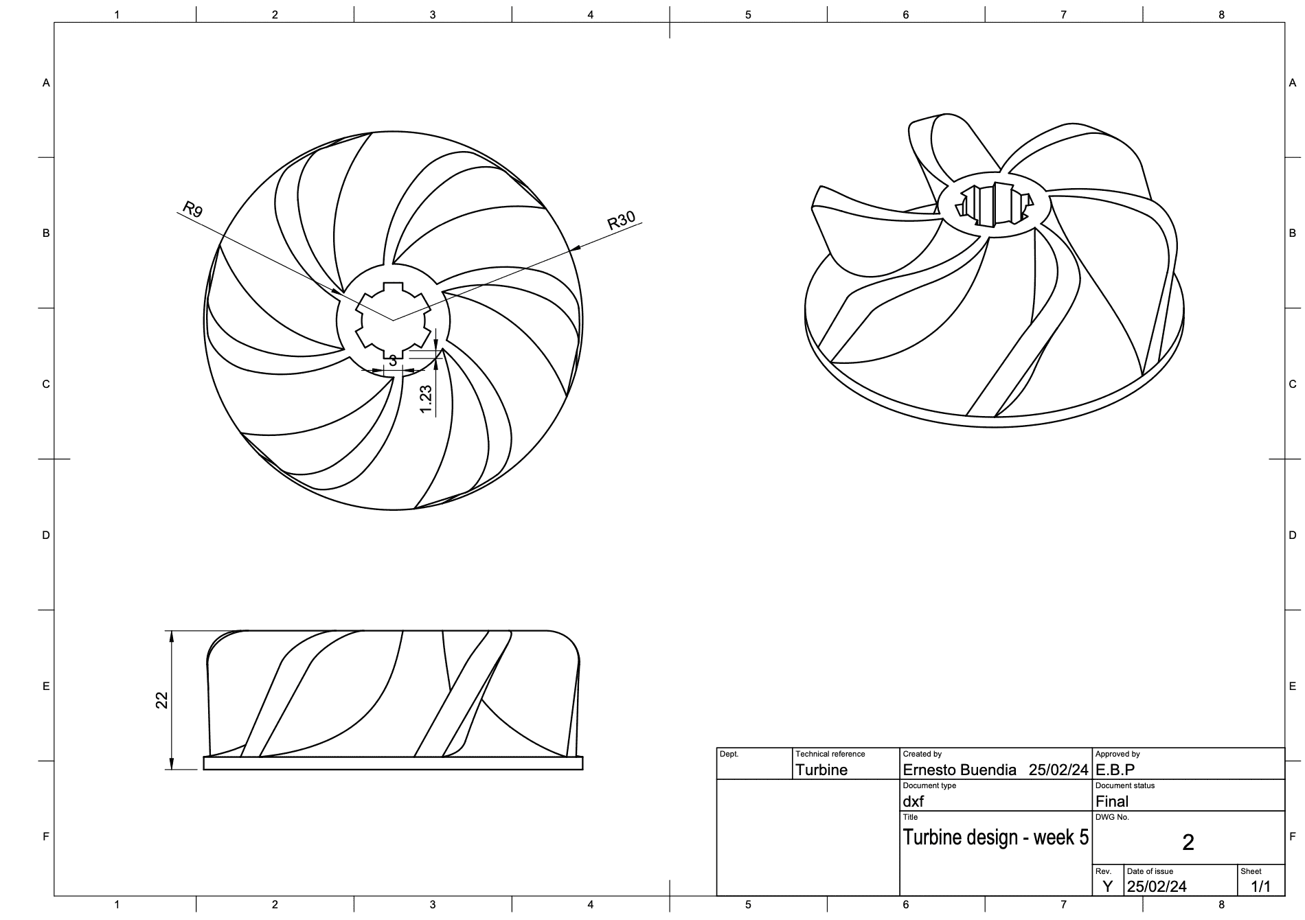
Here is the process I used for design my turbine:
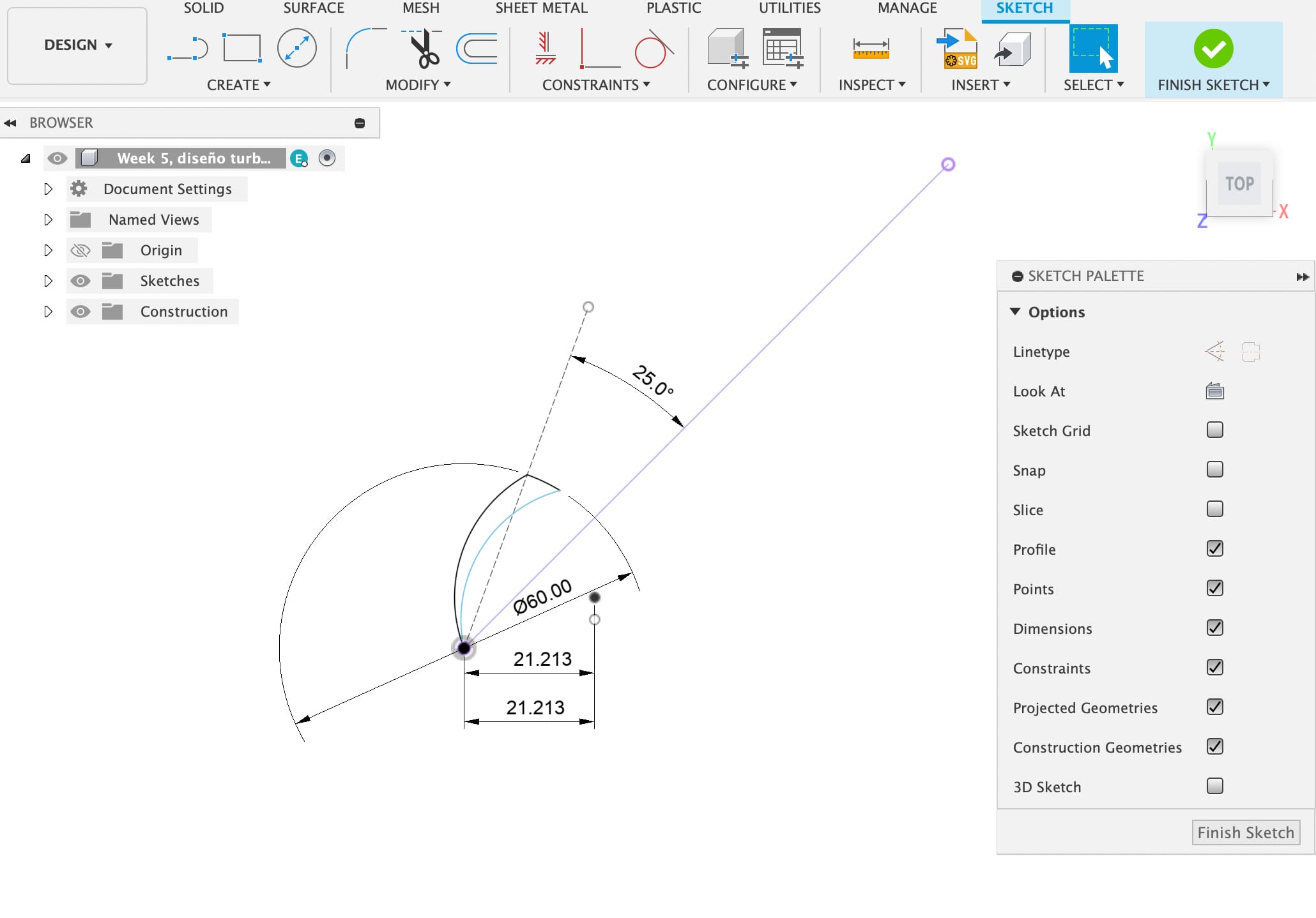
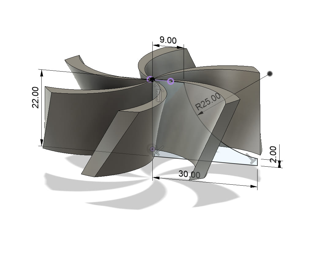
First I create a sketch on a plan and begin to enter the measurements of the turbine blades
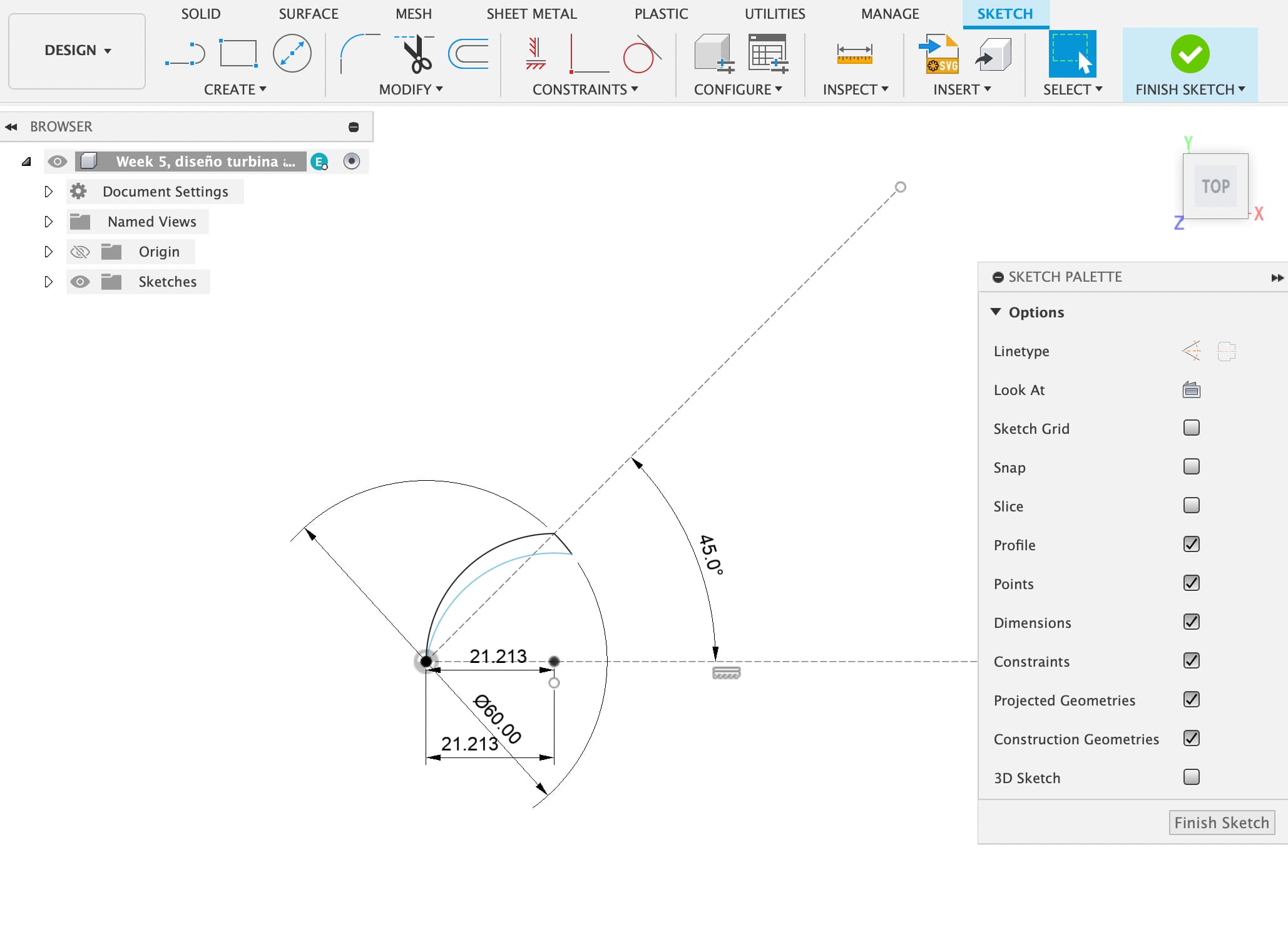
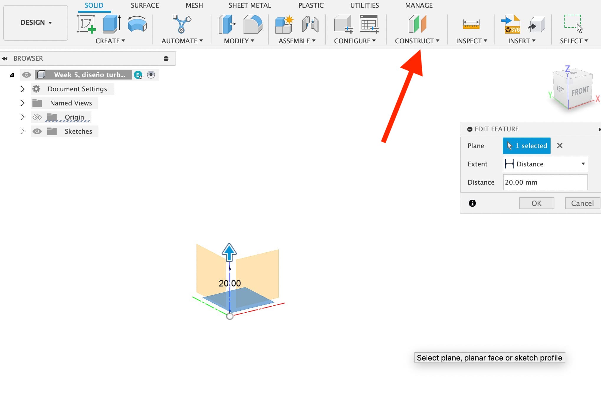
Then I create another plane 20mm away.
On that plane created, I create another sketch with the upper measurements of the blades.
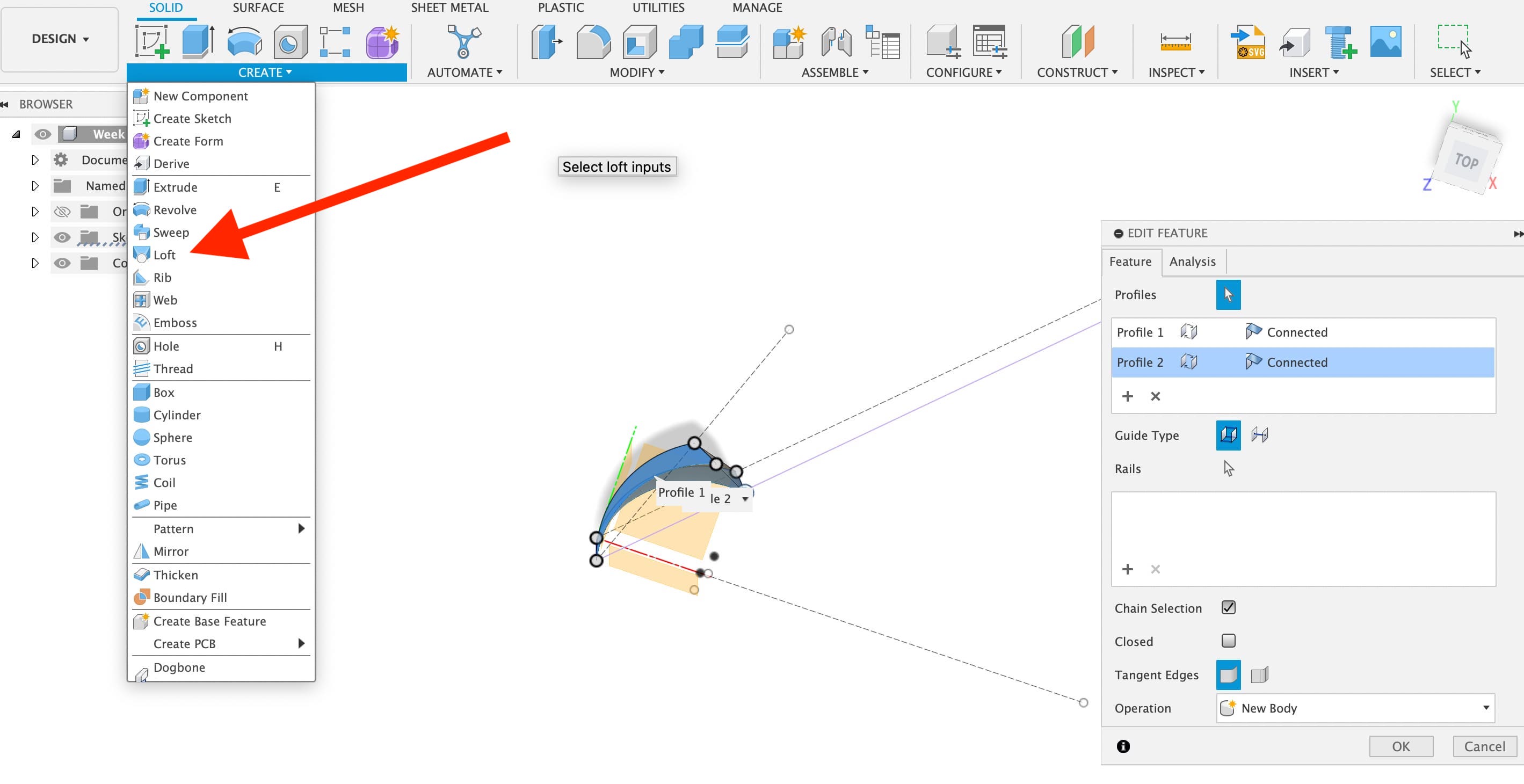
Then I use the "loft" command to create a volume between the two sketches spaced 20mm apart each.
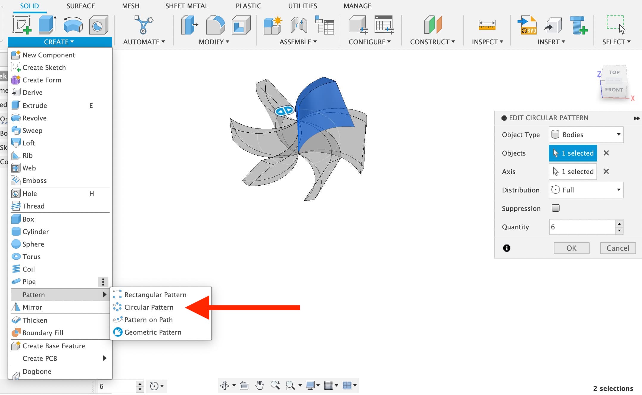
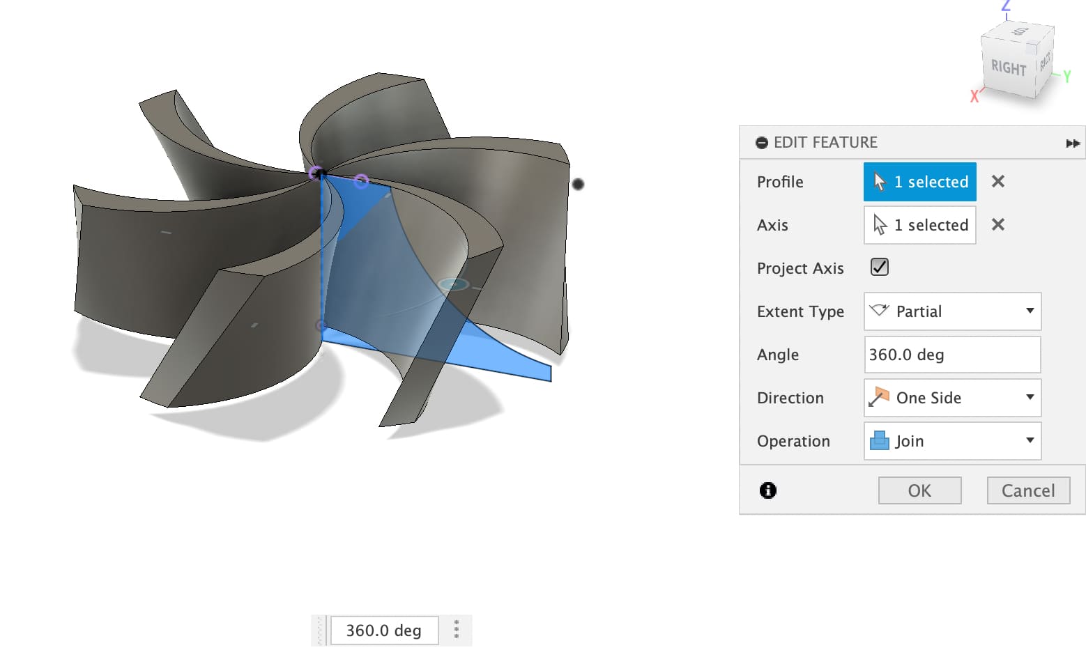
Then, I create a pattern that replicates that cross 6 times.
Now I create another sketch that will give the body to the blades.
With this sketch, I now generate a volume with the revolver option.
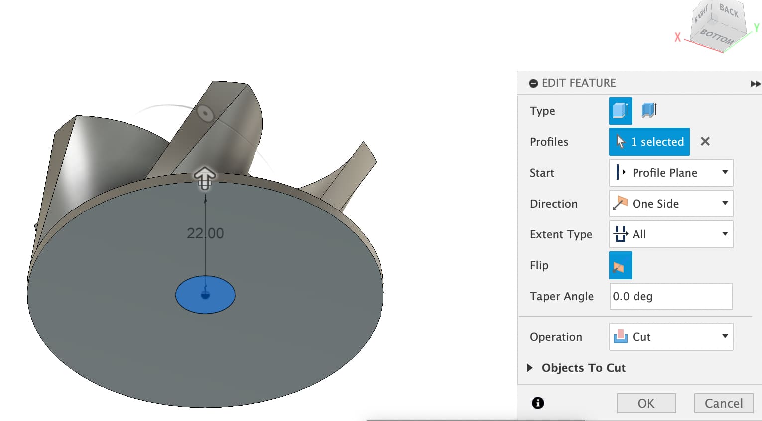
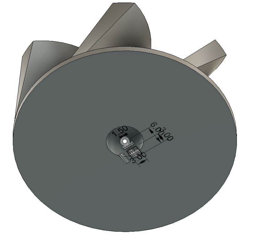
Then, another sketch for the shape of the central hole where a shaft that holds the turbine is supposed to fit.
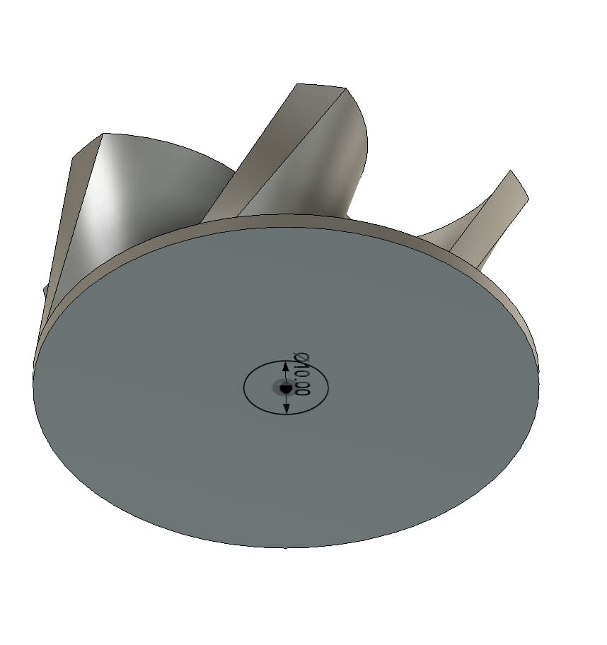
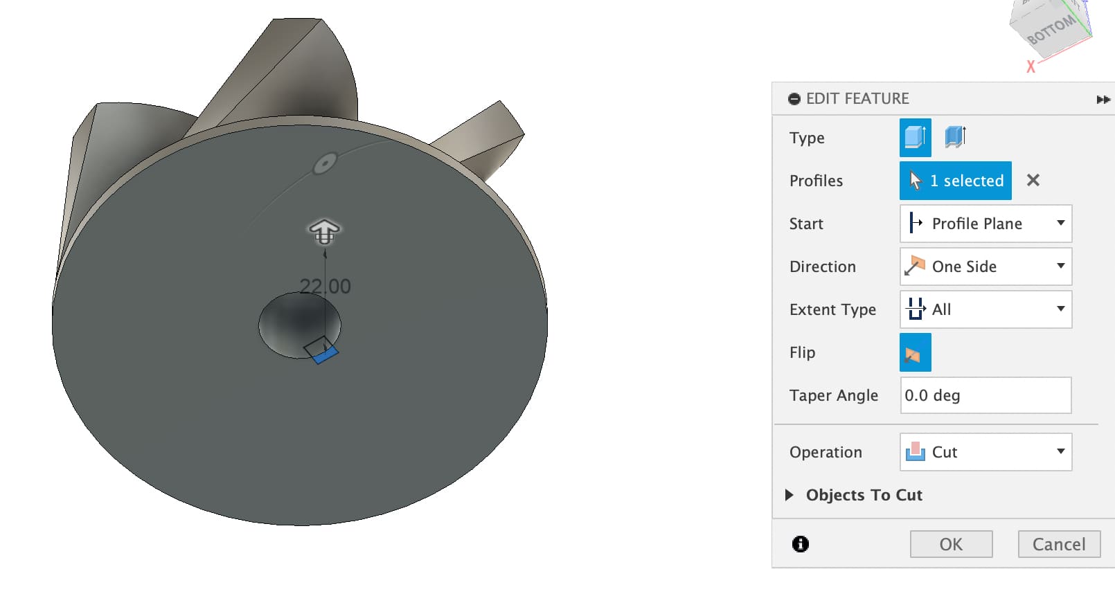
I extrude this sketch along the entire height
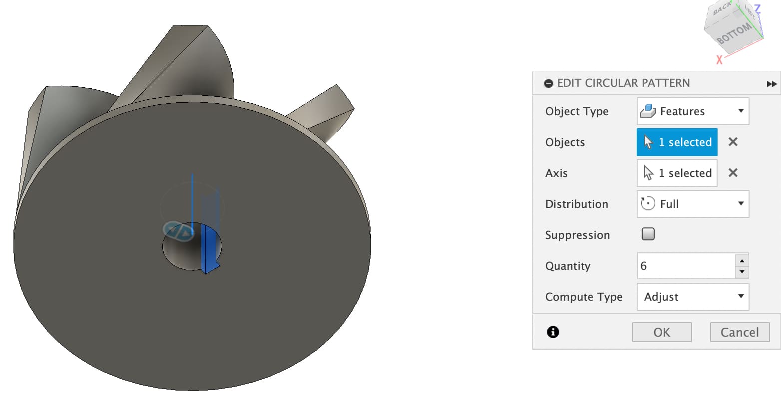
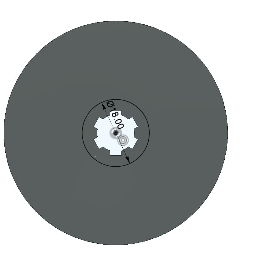
It is also necessary to design the teeth that the clamping shaft will have. For this I create another sketch with that shape
Again I extrude it along the entire height
And now I create another circular pattern, in the same way as the first one.
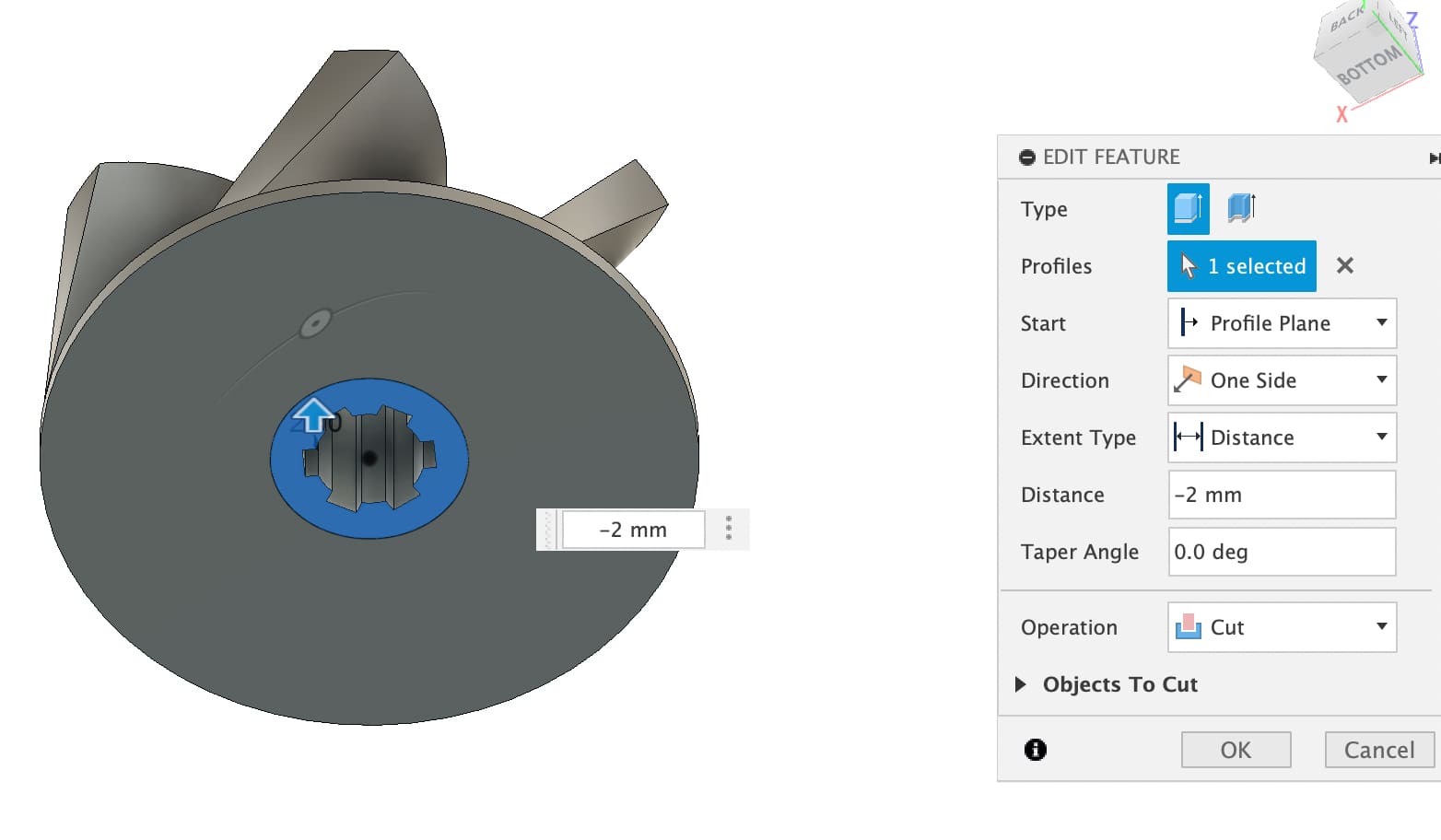
Now I create the sketch of the base of the shaft that would enter the turbine.
And I extrude it 2 mm high
Finally I fillet the corners of the turbine blades and finish with the design
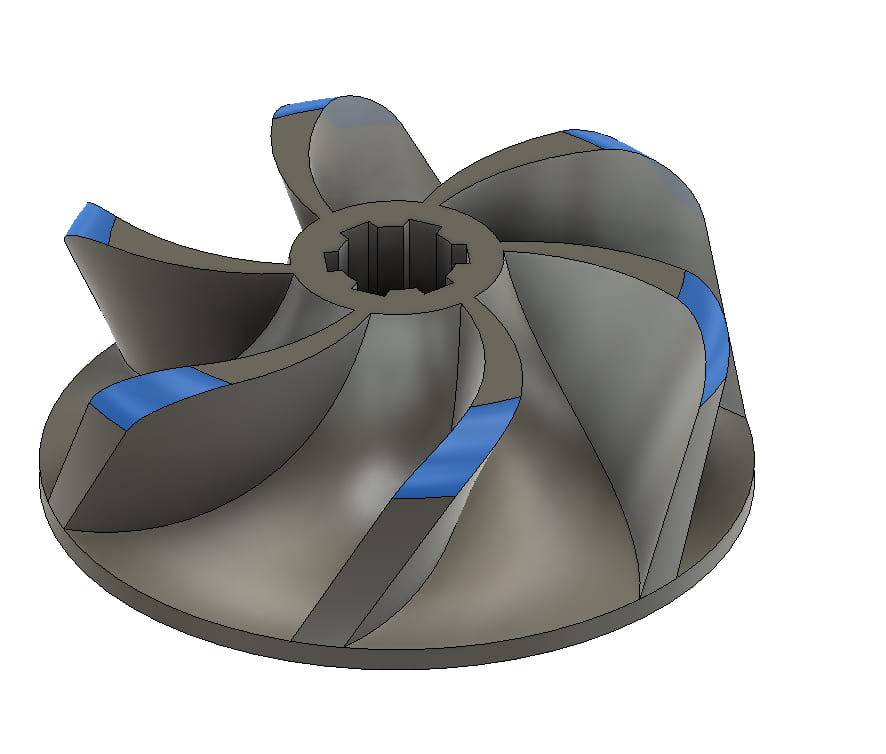
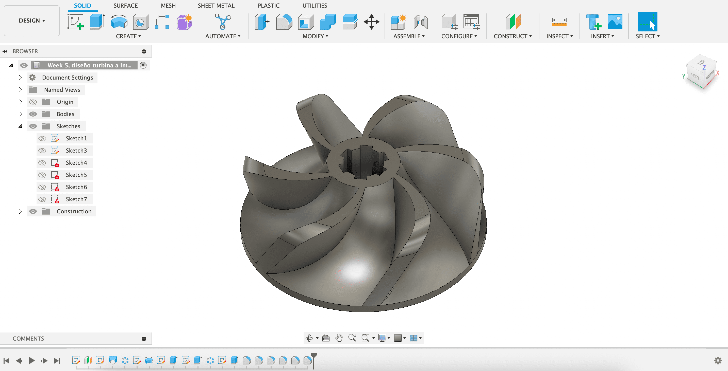
Final design
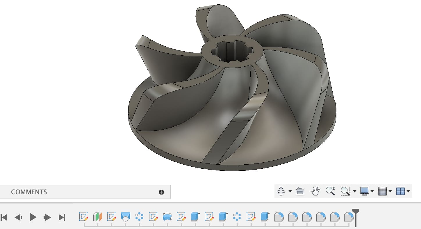
What I like about this fusion 360 software is that it has a timeline bar at the bottom where you can see how the design has been carried out. This is a video of the entire design process:
After the design has been made, we must export it as a stl file to be able to load it into the 3D printer. Once loaded, we define certain parameters as explained below:
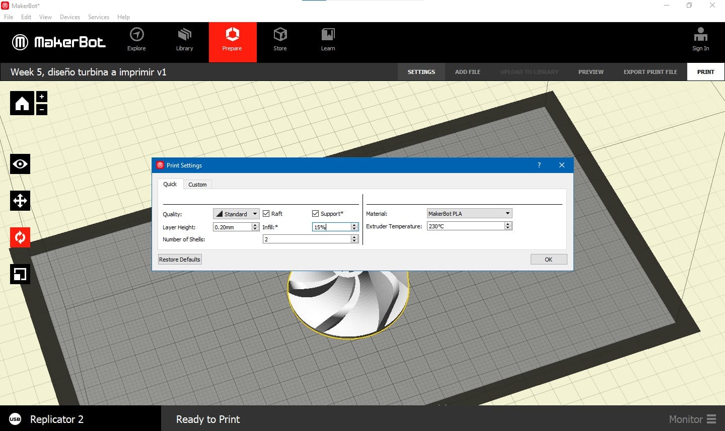
Infill: 15%
Definition: Refers to the density of infill within the printed model.
Importance: Affects the strength and solidity of the printed object. The higher the value, the more solid the interior of the printed object.
Layer height: 0.2mm
Definition: The thickness of each individual layer on which the object is printed.
Importance: Thinner layers may result in a smoother and more detailed surface but can also increase printing time. The choice depends on the desired quality and acceptable printing speed.
Raft: Yes
Definition: An additional layer of printed material on the base of the object to improve adhesion to the printing platform.
Importance: Used to prevent warping and enhance stability during printing. It's not always necessary but can be useful for certain materials and geometries.
Support: Yes
Definition: Printed support structures to hold up parts of the object that protrude and cannot be printed in mid-air.
Importance: Crucial for printing objects with overhangs, bridges, or other features that can't be printed without support. These supports are removed after printing.
Material: PLA (Polylactic Acid)
Definition: The type of material used for 3D printing, such as PLA, ABS, PETG, among others.
Importance: The material affects the physical and mechanical properties of the final object, including strength, flexibility, and printing temperature. The choice depends on the specific needs of the project.
Numers of shells: 2
Definition: Refers to the number of outer layers printed around the object.
Importance: Affects the strength and surface appearance of the object. A higher number of outer layers can provide better visual quality and improve robustness.
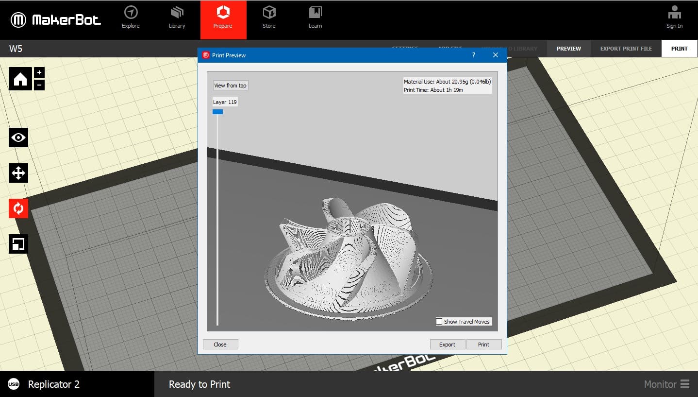
This image is a sample of how the solid will be positioned in the printing chamber and shows us a preview of it.

After the printing is done, this is the result:

3d Scanning
3D scanning is a process that involves capturing the shape and appearance of real-world objects or environments to create digital 3D models. This technology utilizes various scanning devices and techniques to collect data points and create a three-dimensional representation of physical objects.
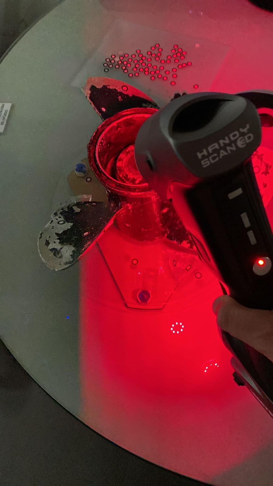
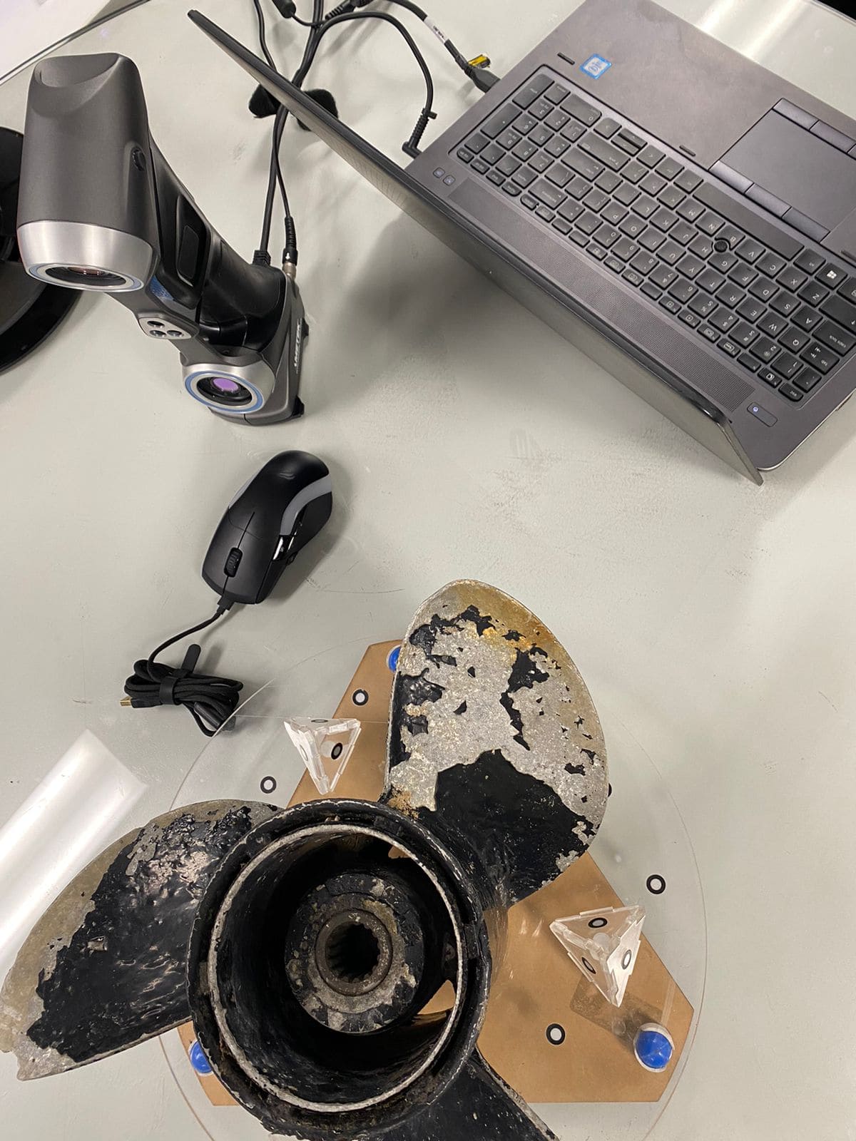
The 3D scanner chosen is the Handy scan 700 from the Creaform brand.I found it interesting to do a 3D scan of an engine propeller because it has blades with certain degrees of inclination and a shape in which you have to be quite careful when passing the scanner.
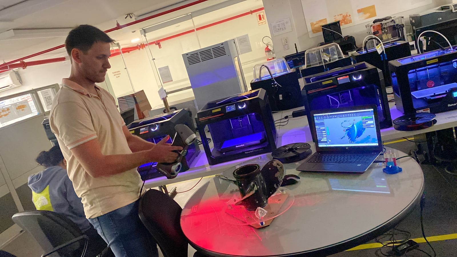
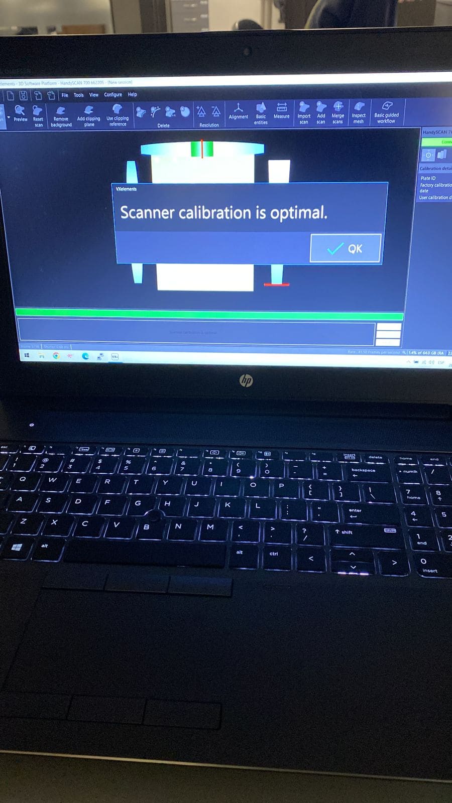
Before scanning, it is necessary to calibrate the position, light and the reference points, which are stickers pasted on the object and which will serve as a guide for the scanner's scanning.
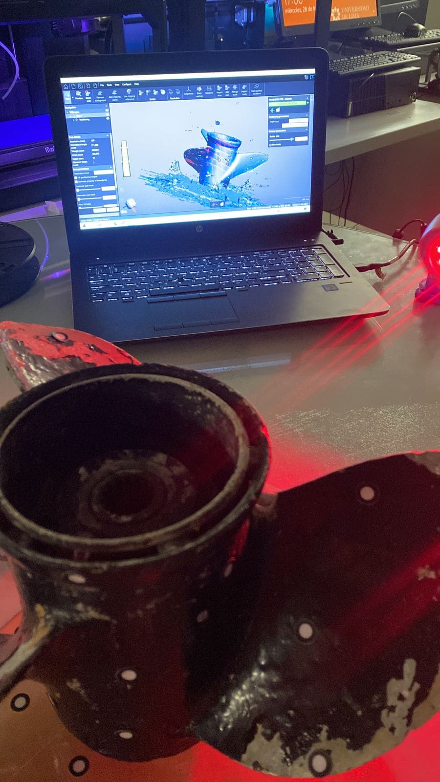
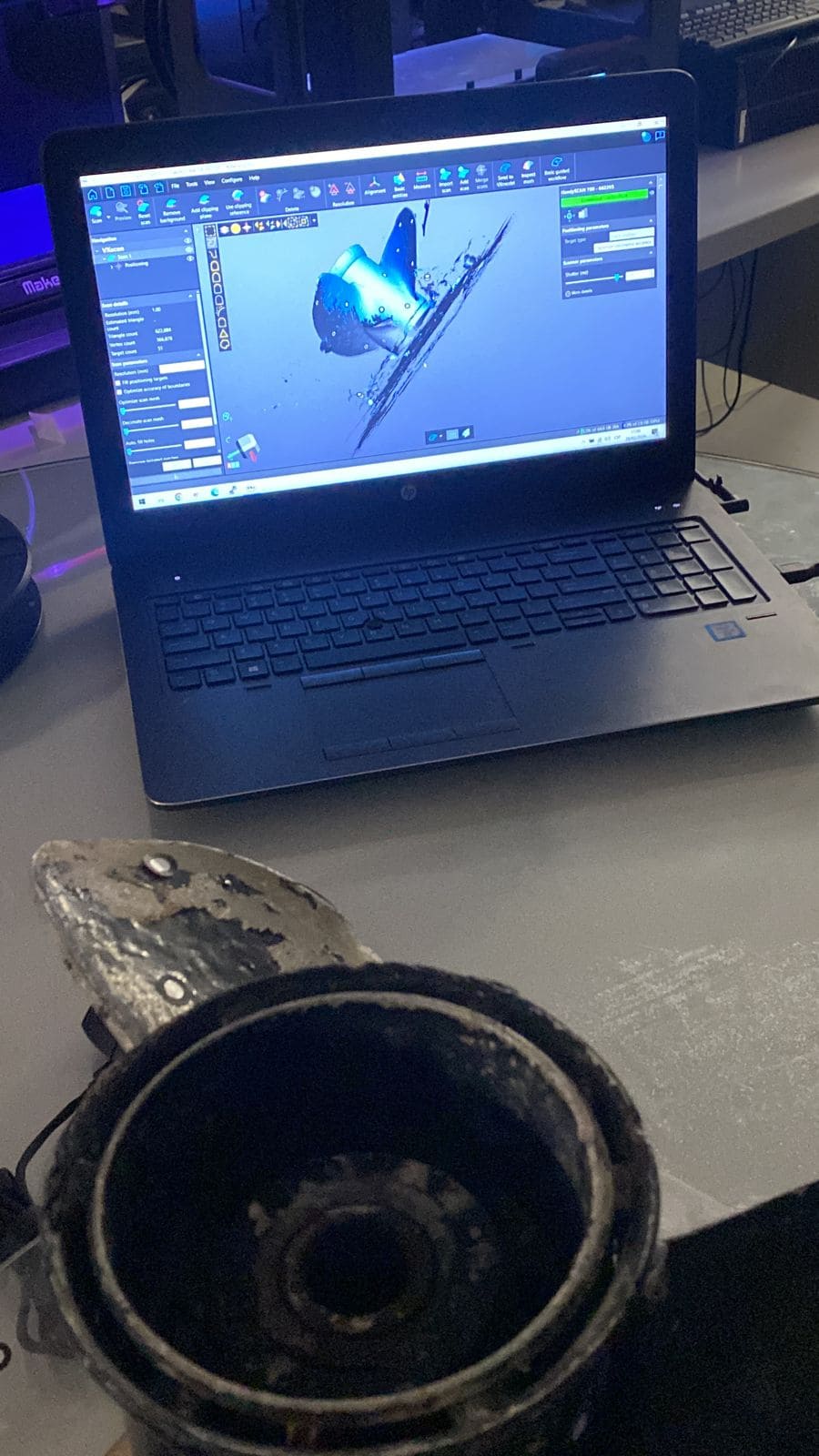
When passing the scanner over the entire piece, care must be taken not to lose the references. If they are lost, you must re-read some previous point and scan again.
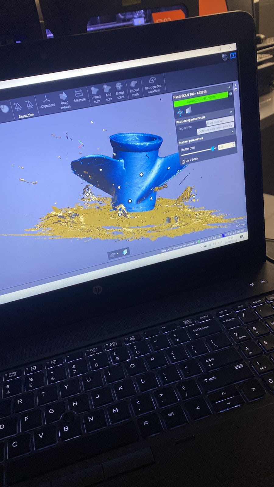
The shutter (ms) parameter refers to a component or mechanism that controls the opening and closing of the light path in the scanner camera during the image capture process. It plays a crucial role in capturing images at specific times and during specific intervals.
Important Note: I chose 6.15mm because of the black shinny color of the propeller.
Group assignment
What I learned from this group experience was thow different layer heights affect print quality and print time. I also learned how to properly calibrate the printer for optimal performance, including bed leveling and extruder calibration and finally the workflow for 3D Printing: design, slicing, printing and post-processing (cleaning and removing supports). This was my first time using a SLA printer machine, and i must say that the resolution I saw was incredible.
My contribution to the group work was to test the design rules of the Sonic Mighty 8K Phrozen SLA (Stereolithography) 3D Printer . I used the following parameters:
-Layer Height: the recommended layer height is 0.01 to 0.05 mm, we used 0.05mm.
-The wall Thickness was of 0.4 mm.
-Support Structures: manual because the voronoi dragon we made had areas that were difficult to access inside, and it was going to be difficult to remove the supports.
The process of printing in this machine was similar than the others: 3D design, then Slicing and finally the printer Setup (Fill the resin tank with photopolymer resin) and load the sliced file into the printer via USB.
During printing, the build platform is submerged in the resin and positioned just above the transparent bottom of the tank. An LCD screen combined with a UV LED array selectively cures each layer of resin, forming the model layer-by-layer. This process repeats until the entire model is printed.
After printing, the model is removed from the build platform and cleaned with isopropyl alcohol to remove any uncured resin. The model is then post-cured under UV light to ensure it is fully hardened and reaches its maximum strength. In my opinion, this sonic sighty 8K offerd the highest resolution.
-Resin used: Aqua resin green/ivory 4k - 50um.
Here is the link to the group assignments:
Files: