Week 4 assignment: Electronics Production
Summary
This week's goal is to characterize the design rules for the in-house PCB production process and document the workflow for sending a PCB to a board house. Also, I had to make and test a microcontroller development board.
Having done quite a few tests, it was possible to find the production parameters, however, I found it a little difficult and with many things to consider that are detailed below.
Process
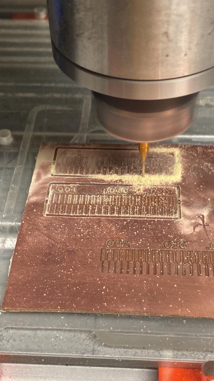
The Fablab has a Roland machine model: MDX-540 in which the PCB traces and outline cut were made.

The process to begin manufacturing a PCB is detailed below:
1) We start with an image in PNG format with the traces to be made for our PCB. This information is processed on the FabAcademy web simulator: "https://modsproject.org/" to obtain the G code as a result.
Important Note: It is important to work with a high quality image.
It is also possible to work with a file in "svg" format, depending on the software with which the circuit design is being worked on.
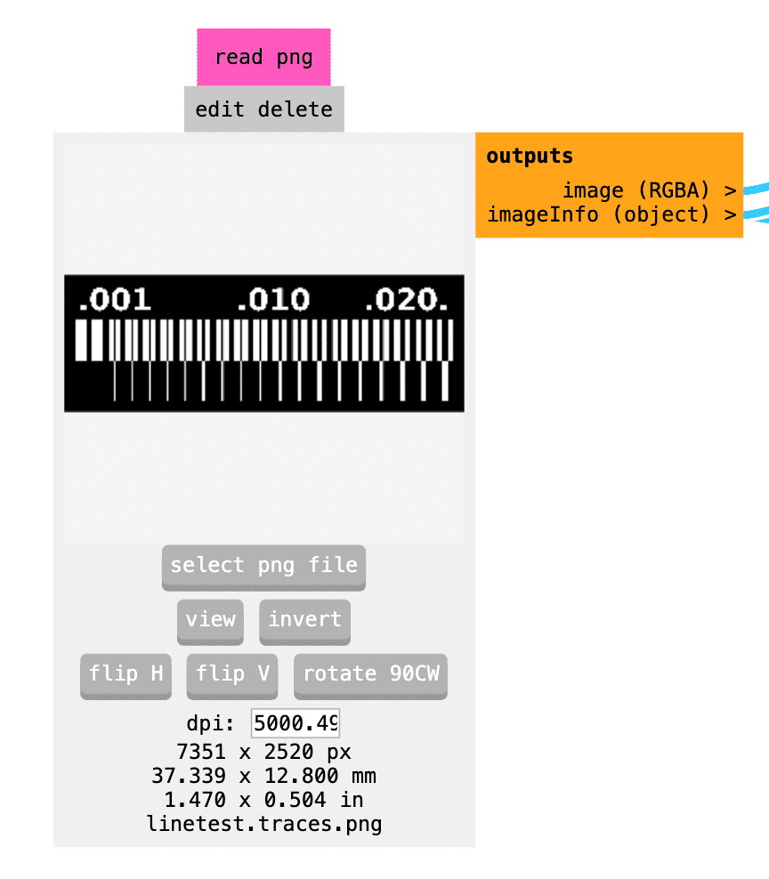
2) Now in the web simulator, we proceed to configure the parameters we want. After several testing in a fiberglass board, we define the following parameters:
- Work with a cutter diameter of 0.1mm and a cutting depth of 0.1mm.
- 4 offsets and a stepover of 0.5.
- For the traces the 0.30mm mill was used and for the outline the 0.8mm.
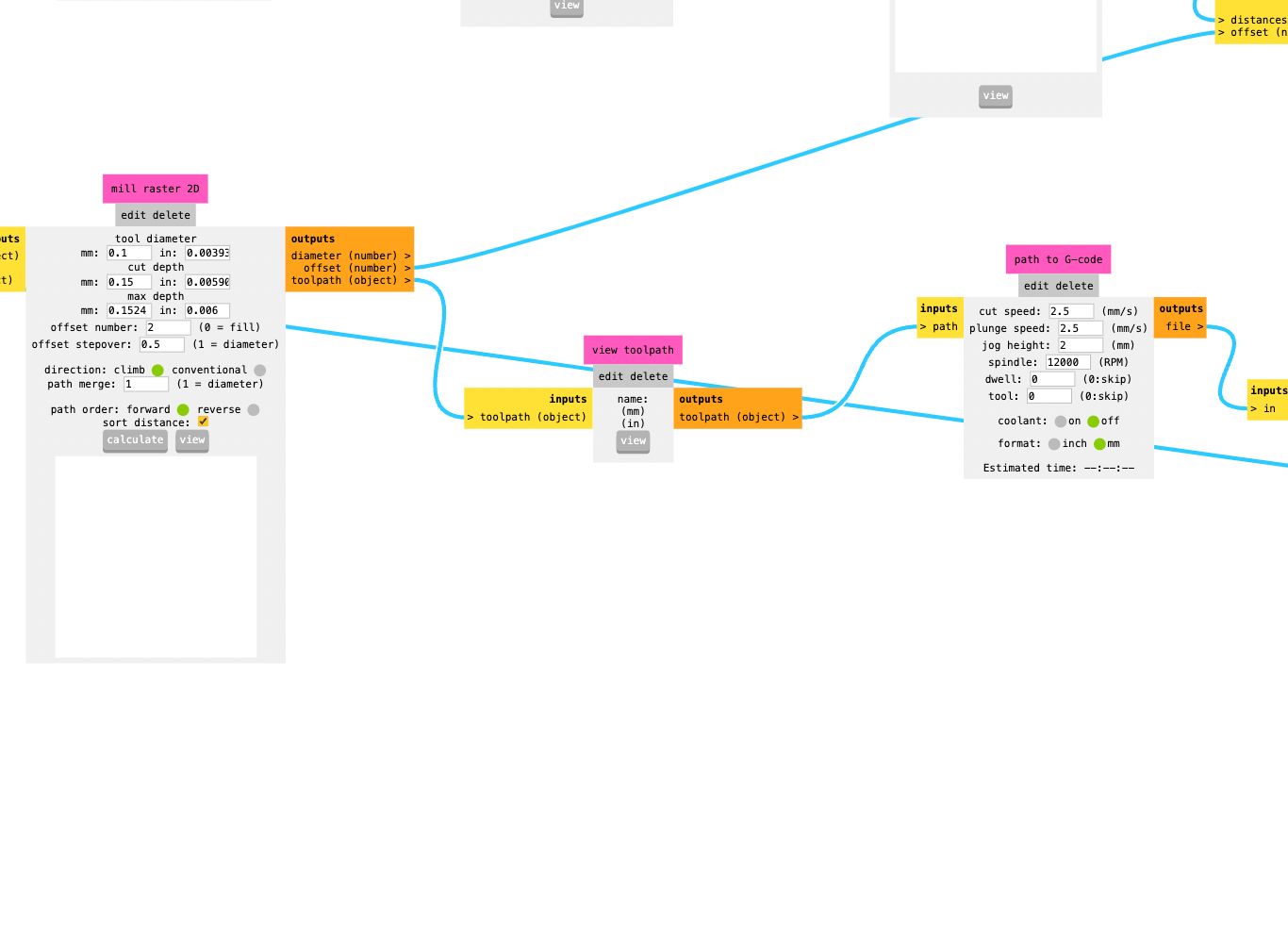

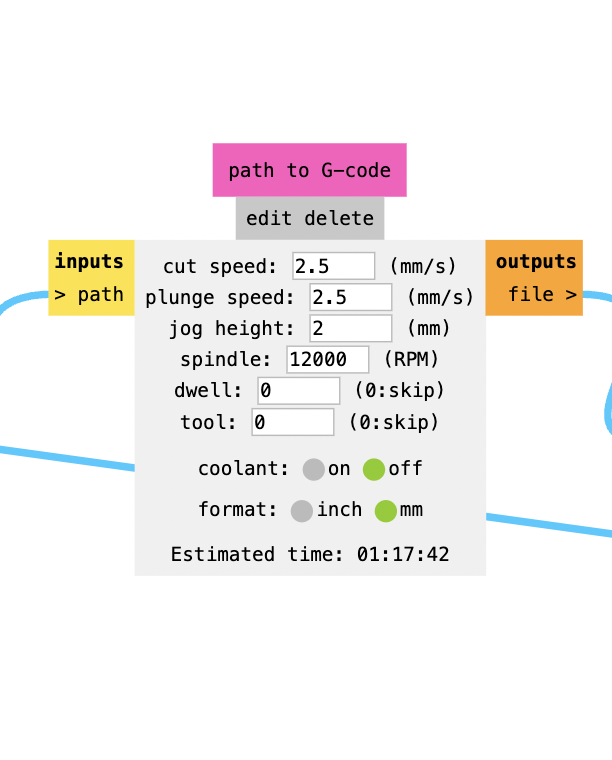
3) With the configurations already set, we proceed to calculate the G code and we can see how our work would turn out. G codes are used to command specific actions for the machine: such as simple machine movements or drilling functions.
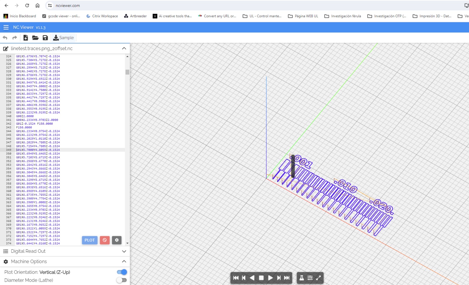
4) Once calculated, the G code file is automatically saved to the computer. Finally, this file will provide all the instructions and coordinates that the Roland machine needs to be able to manufacture the PCB.
Important note: It is necessary to correctly calibrate the 3 axes. The "x" and "y" axis will help us position ourselves on the lower left side of our board, using the "origin" command. For the "z" axis, it is necessary to calibrate it every time the milling cutter is changed with the "z zero" command.
If there is any error in the calibration of this axis, the machine head will begin to move without any direction as can be seen in the following video. In this case, it must be reconfigured by adjusting the position of the cutter with respect to the jaws.
PCB manufacturing
This week I also have to make an already designed board. The authors of the design of this board are Quentin Bolsée and Adrián Torres , named as "Quentorres".
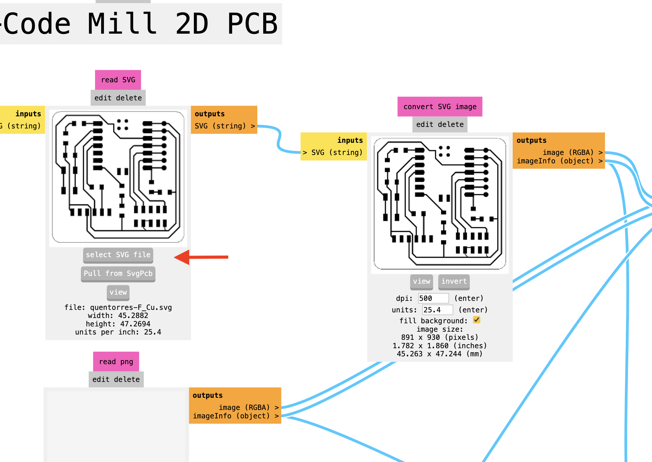
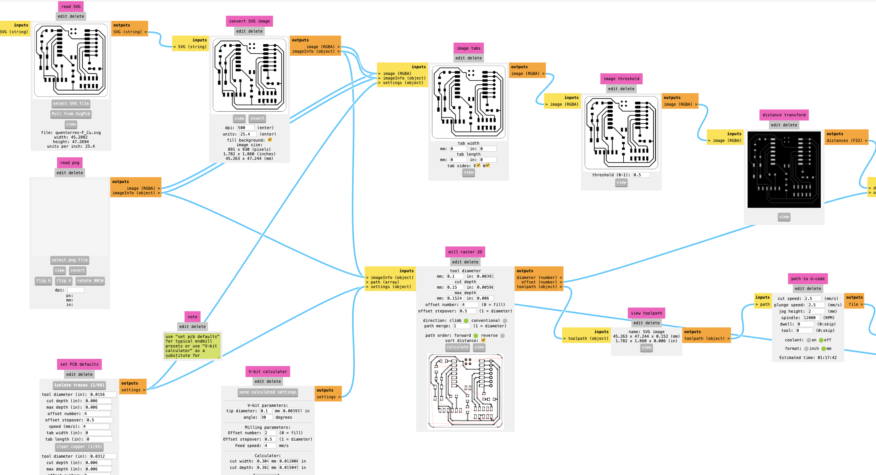
The PCB manufacturing process began with the design in "svg" file given by our local instructor Italo. This file is loaded into the simulator "https://modsproject.org/" configuring the parameters we tested before.
Here is the process I followed to produce the Quentorres design:
First I had to choose the "svg" option because that type of file is the one I had received as the design of the plate. There is another way to work with another type of "png" file as well.
Then, select the "isolate traces" option to detect the traces of the plate.
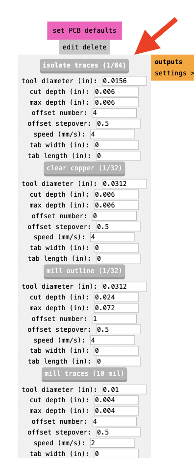
Next, I set the following parameters to "mill raster":
- tool diameter: 0.1mm
- cut depth: 0.15mm
Then, I click the "calculate" button for calculating the traces that the mill will make and to automatically download the g code.
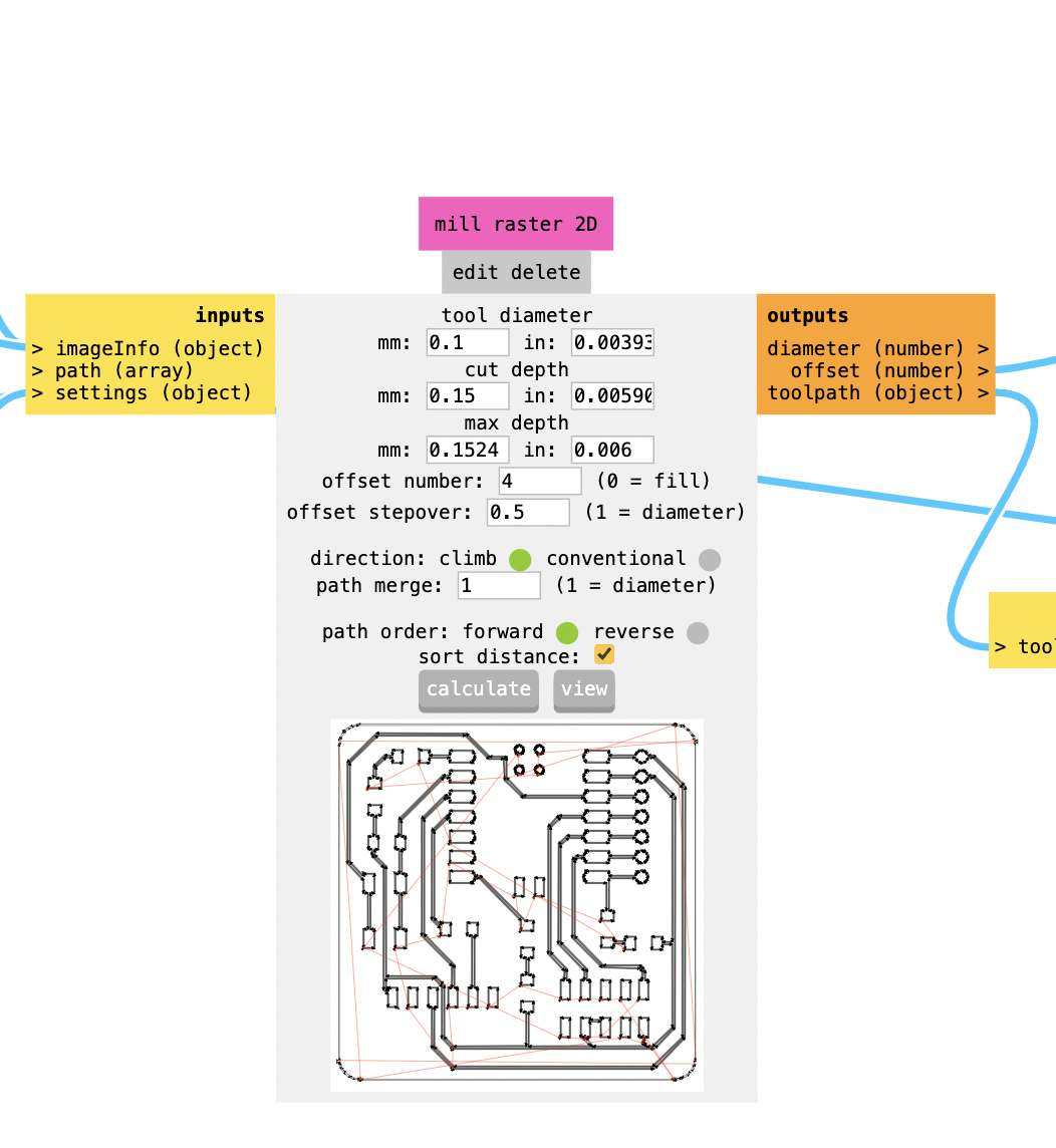
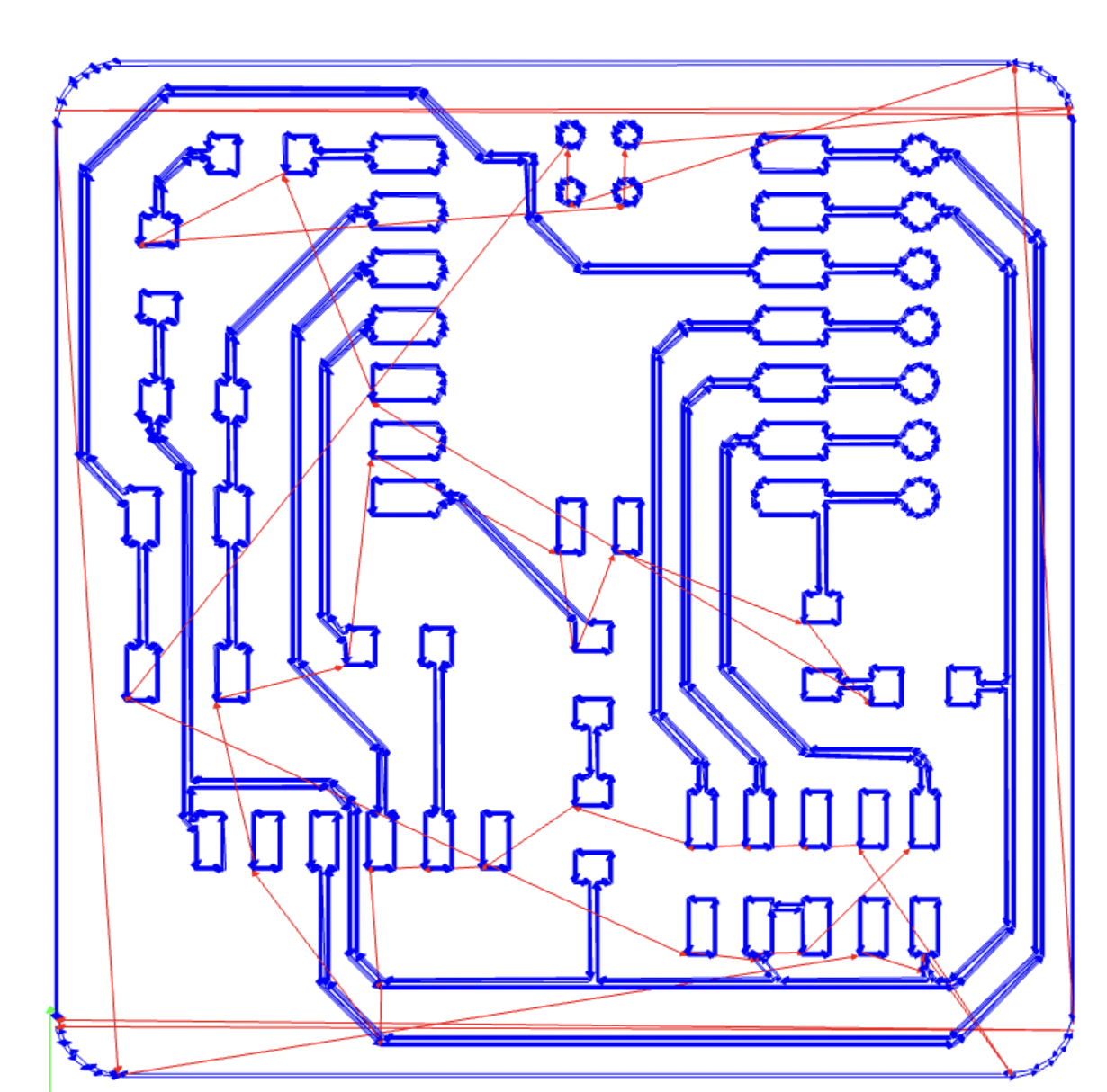
This is a preview of how the cutter will be moving in the Roland machine.
Finally, you must change the revolutions per minute (rpm) of the cutter to 12,000, which is the maximum work.
This is the global flow of how to configure the production of a pcb in mods
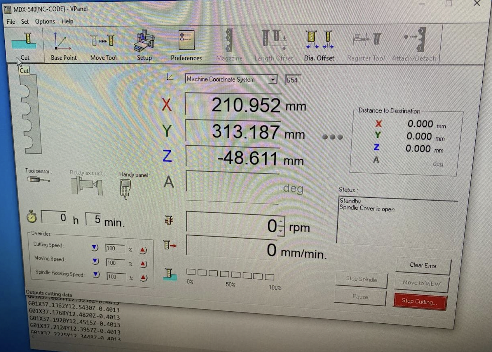
After generating the G code, it is loaded into the "V-Panel" software on the Roland machine. V-Panel (Virtual Panel) is a control software designed to interface with Roland DG’s digital fabrication machines. It provides a user-friendly graphical interface that allows users to manage machine operations, perform maintenance tasks, and monitor job progress directly from their computer.
Recommendations to take into account:
-cutting mill in good condition
-fix the entire board with double contact tape
-use lubricating oil when milling
-remove dust with a vacuum cleaner
Since I have been using FR4 plates with fiberglass, I have considered using the following personal protection elements.
- Gloves: To protect hands from chemicals and fiber material.
- Safety Glasses: To prevent particles and chemicals from entering the eyes.
- Masks or Respirators: To avoid inhalation of fiber dust and toxic vapors.
- Protective Clothing: To avoid direct contact with chemicals and irritating materials.
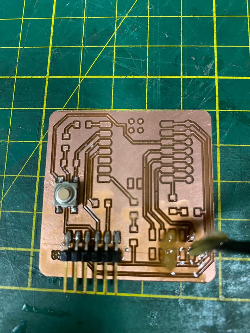
Finally, we test the copper tracks and confirm that there is continuity of current between them, ensuring optimal manufacturing quality.
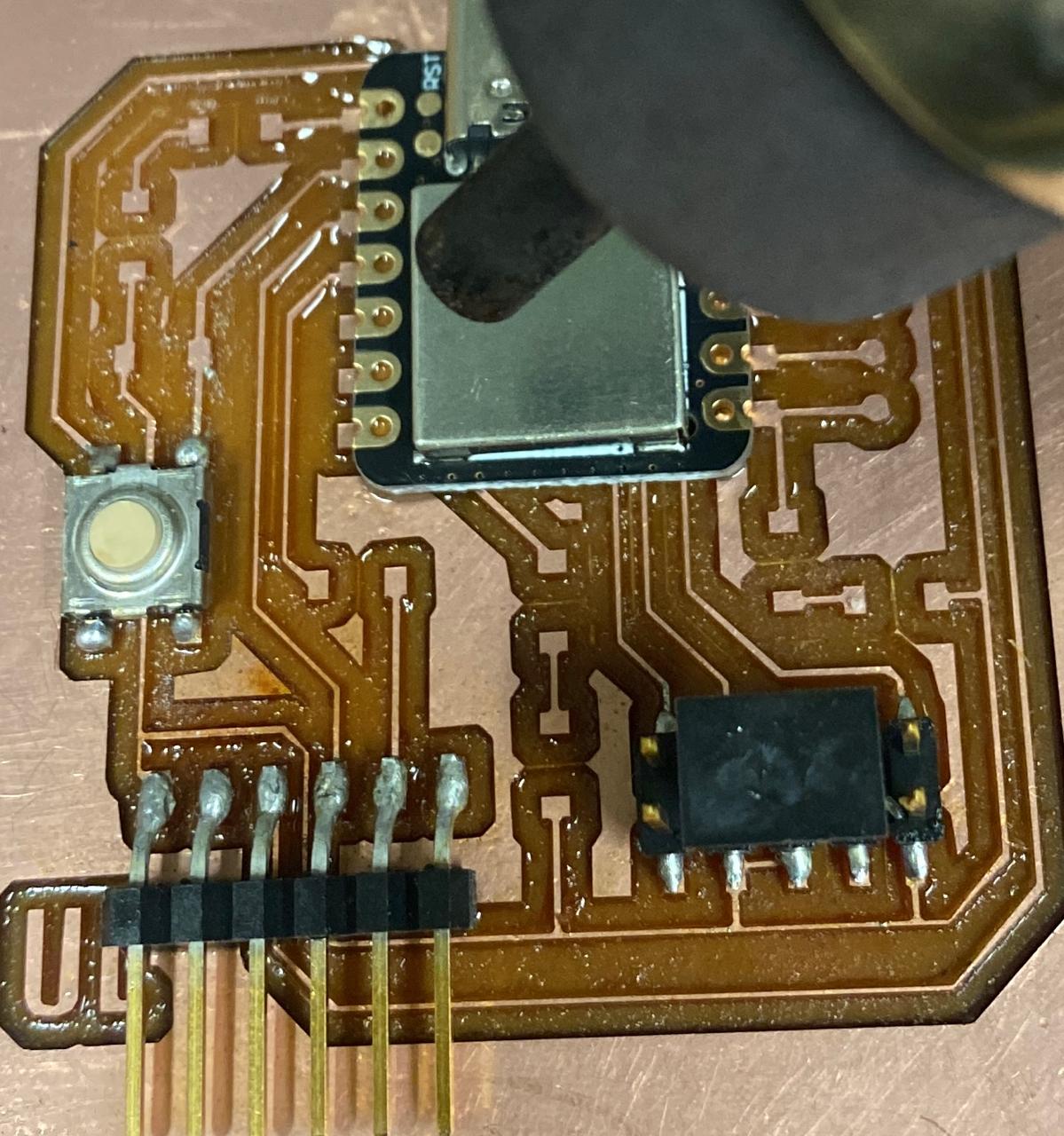
PCB soldering
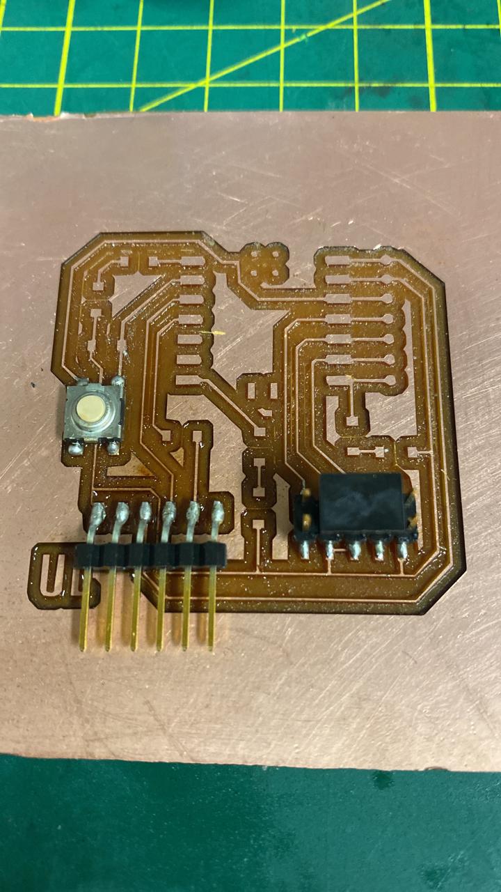
The board soldering process begins after the manufacturing of the copper tracks is completed. At this stage, the following components are soldered:
-3 LEDs (test diodes with multimeter)
- 1 SMD female pin header (x6)
- 1 pin header SMD male 90 degrees (x10)
- 1 SMD push button
- 4 1k resistors (1001)
- 1 470k resistor (4701)
- 1 seeduin

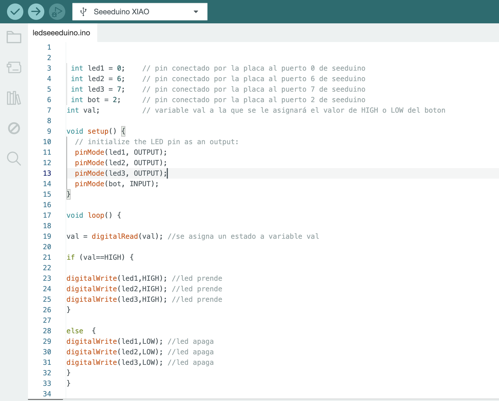
After the board was solded, I wrote a simple code to turn on the 3 leds at the same time at the moment the button is pushed.
In order to upload the programming code to the Quentorres board, I must first upload it to the Arduino IDE software.
The Arduino Integrated Development Environment (IDE) is a software application used to write, compile, and upload code to Arduino boards. These are the steps I followed:
1. Download and Install:
The Arduino IDE can be downloaded from the official Arduino website.
2. Write Code:
After launching the IDE, I wrote the code.
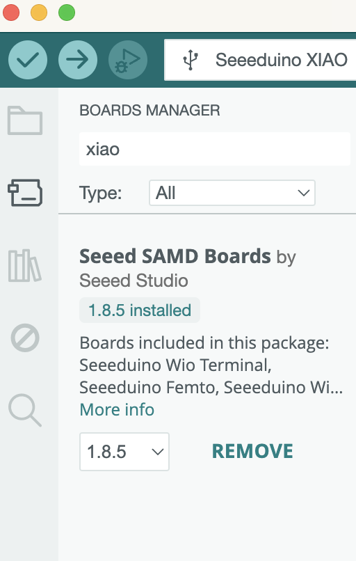
3. Select Board and Port:
I downloaded and selected the board for the XIAO SAMD21.
4. Verify and Upload:
I used the "Verify" button to compile the code and check for errors. After verifying, click the "Upload" button to transfer the code to the XIAO seeeduino SAMD21 board.
Optional: 5. Monitor and Debug:
The Serial Monitor can be opened to observe data sent from the board, which is useful for debugging purposes. In this code, I did not use the serial monitor.

Group assignment
What I learned from this group experience was the optimal feed rates and spindle speeds. Also, the correct depth for cutting traces and the board outline to avoid incomplete cuts or board damage and finally undesrtanding the step-by-step process of producing a PCB.
Here is the link to the group assignments: