Week 15 assignment: Interface and Application Programming
Summary
This week I had to write an application that interfaces a user with an input &/or output device that I made.
Process
For this week, I uses Blynk app. It is a platform designed for the Internet of Things (IoT), which allows users to build web and mobile applications to control and monitor hardware remotely.
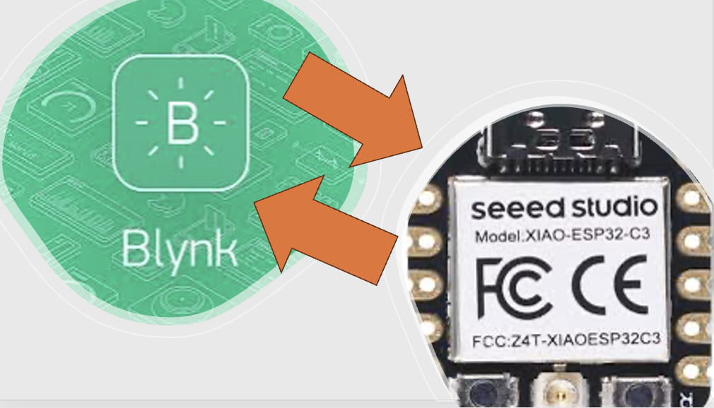
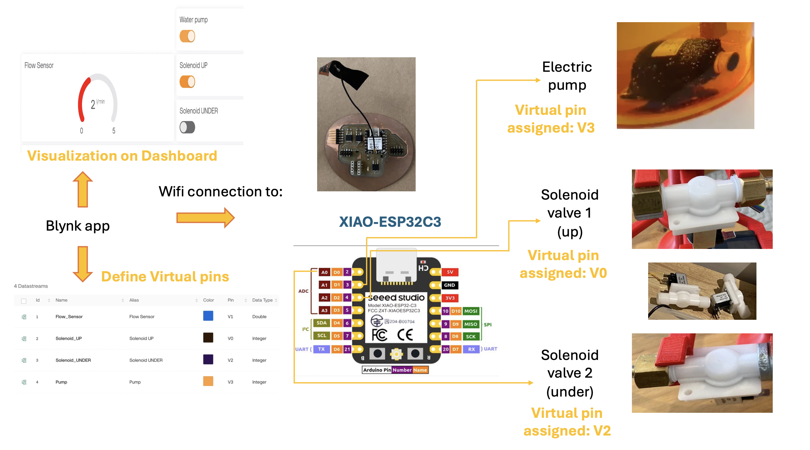
I used it to start controlling the actuators and sensors of my final project using the Seeeduino XIAO ESP32-C3:
-Turn on or turn off the electric pump.
-Read the flow sensor information in the app Blynk.
-Activate or deactivate the solenoid valves.
The highlights of this app are:
BLYNK APP:
Blynk is an innovative platform that bridges the gap between hardware devices and mobile or web applications, making IoT projects easier and more accessible. Blynk provides a comprehensive ecosystem that includes mobile and web applications, cloud services, and a variety of libraries that support multiple hardware platforms.
Key Features:
-Drag-and-Drop Interface: It offers a user-friendly drag-and-drop interface in its mobile and web apps, allowing users to quickly design custom dashboards without needing advanced coding skills.
-Wide Hardware Support: It supports a wide range of microcontrollers and single-board computers, including ESP8266, ESP32, Arduino, Raspberry Pi, and many others. I will use it for my final project with an ESP32C3 microcrontroller.
-Widgets: The platform provides a variety of widgets like buttons, sliders, graphs, displays, and more, which can be used to interact with the hardware. Widgets can be configured to send and receive data from the connected devices. I used them to send and recieve data to my board.
-Real-Time Data: Blynk allows real-time data monitoring and control. Users can see live updates from their sensors and actuators and control them from anywhere in the world. I was able to sense in real time the water flow.
-Blynk Cloud: Blynk offers a cloud service where users can store and process their data. The Blynk Cloud handles the communication between the hardware and the mobile or web app, ensuring secure and reliable data transfer.
Blynk Local Server: For advanced users, Blynk provides the option to set up a local server. This can be beneficial for projects that require a high level of security or need to operate independently from the internet.
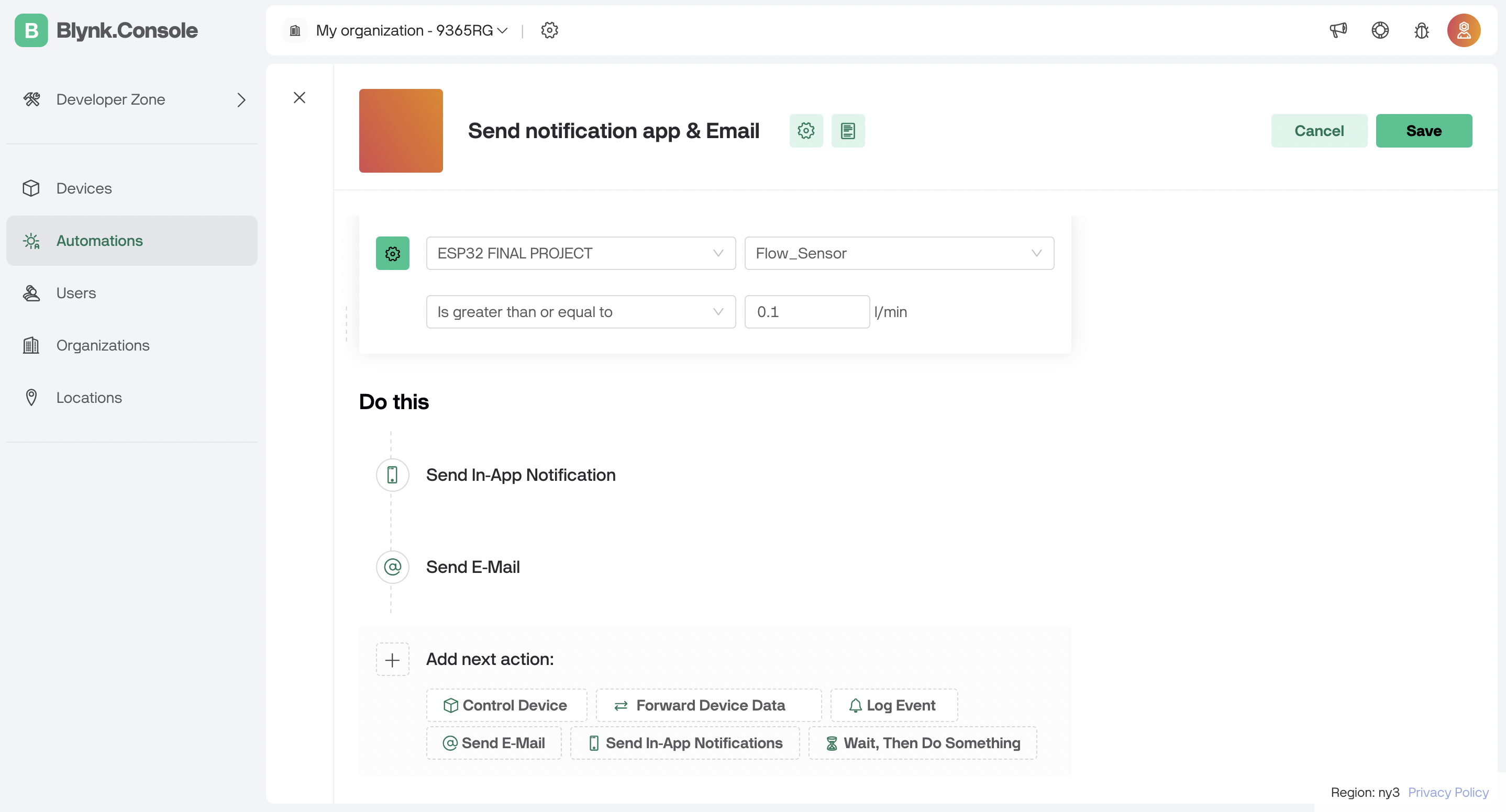
Automations and Notifications (this is a key feature for my final project): Users can set up automation rules and notifications. For example, they can create rules to turn on lights at a specific time or receive alerts when a sensor reading goes beyond a certain threshold. At the beginning of my project, I wanted to control the activation and deactivation time of my solenoid valves with an RTC module, however, upon seeing the advantages of this automation, I chose to use them and leave aside the RTC module.
I will use the seeeduino ESP32-C3 again, which has built-in adaptability to connect to a Wi-Fi network through which it can send and receive data. I will be elaborating my first sketch code for my final project in arduino IDE.
Steps for creating my application
I created the application with a Seeeduino Xiao ESP32-C3 and the Blynk app, I followed these steps:
1. Set Up Hardware: I already have the Seeeduino Xiao ESP32-C3, the flow sensor, the 2 solenoid valves and the electric pump.

2. Install the Blynk Library:
In the Arduino IDE, go to Sketch > Include Library > Manage Libraries.
Search for "Blynk" and install the Blynk library. In my case, it is already installed (that´s why it appears "remove").

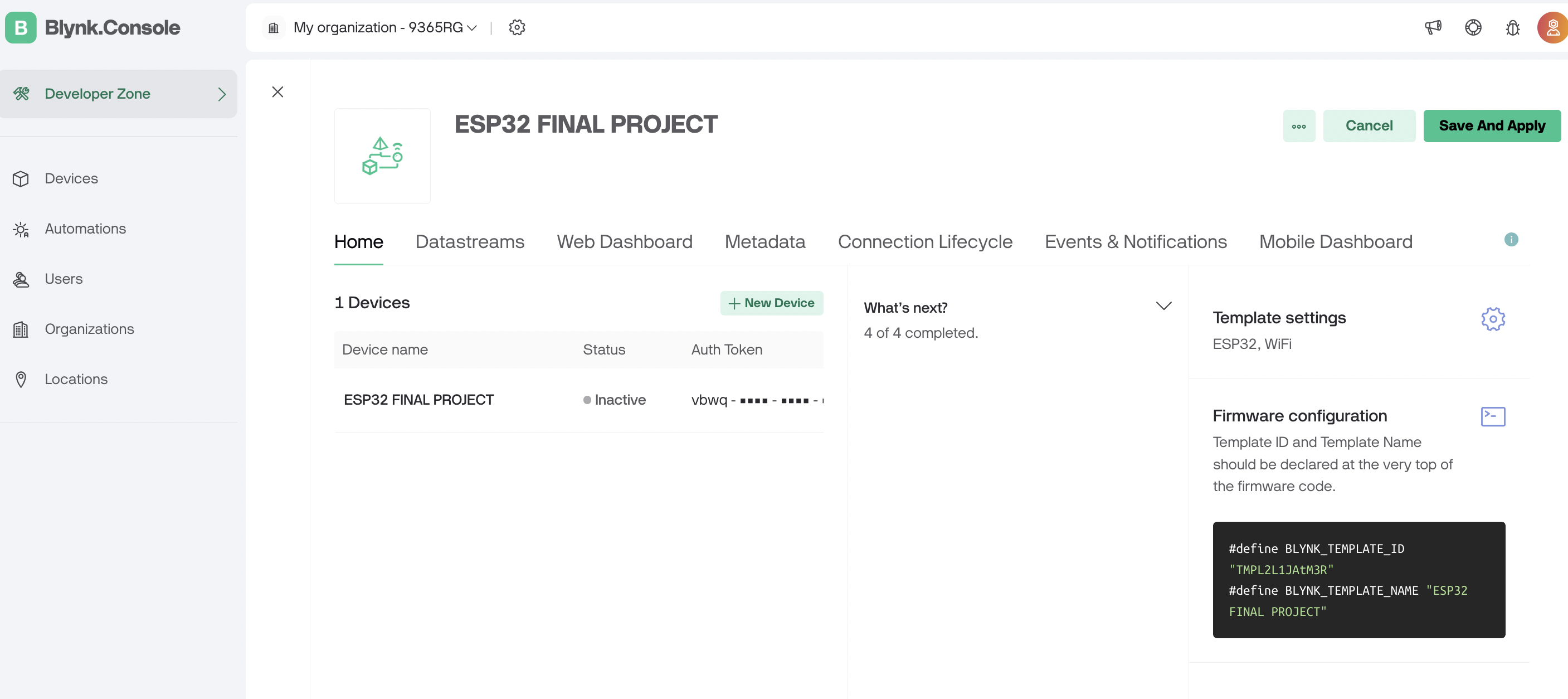
3. Configure the Blynk App in the computer:
I had to register and then log in at:
https://blynk.io/
Inside my account, I had to create a new project and select ESP32 as the hardware and copy the "Auth Token" provided by Blynk.
Then, I created the datastreams, which serve as communication channels through which data is transmitted between my seeeduino esp32c3 and the Blynk Server. The will facilitate real-time interaction and control of IoT. I created 4: one for each the solenoid valve, 1 for the sensor flow and 1 for the electic pump.
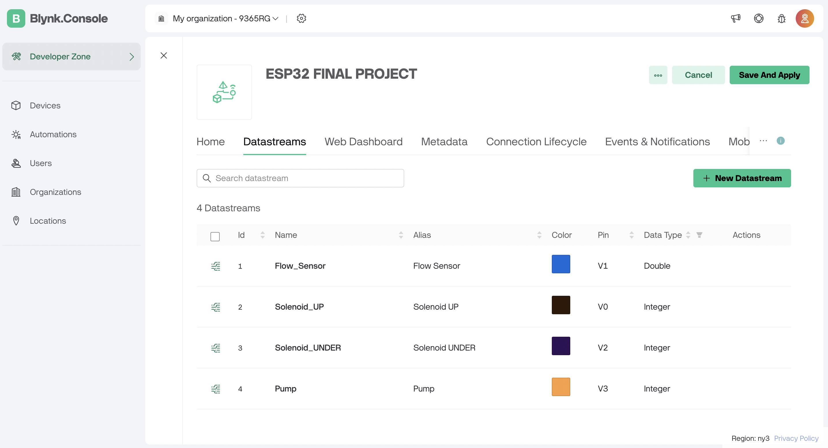
Each datastream can be configured as you wish: I set the flow sensor as double because I wanted to store my values with two decimal places. The range of this sensor goes from 0 to 15 l/min, but you define it as you consider best.
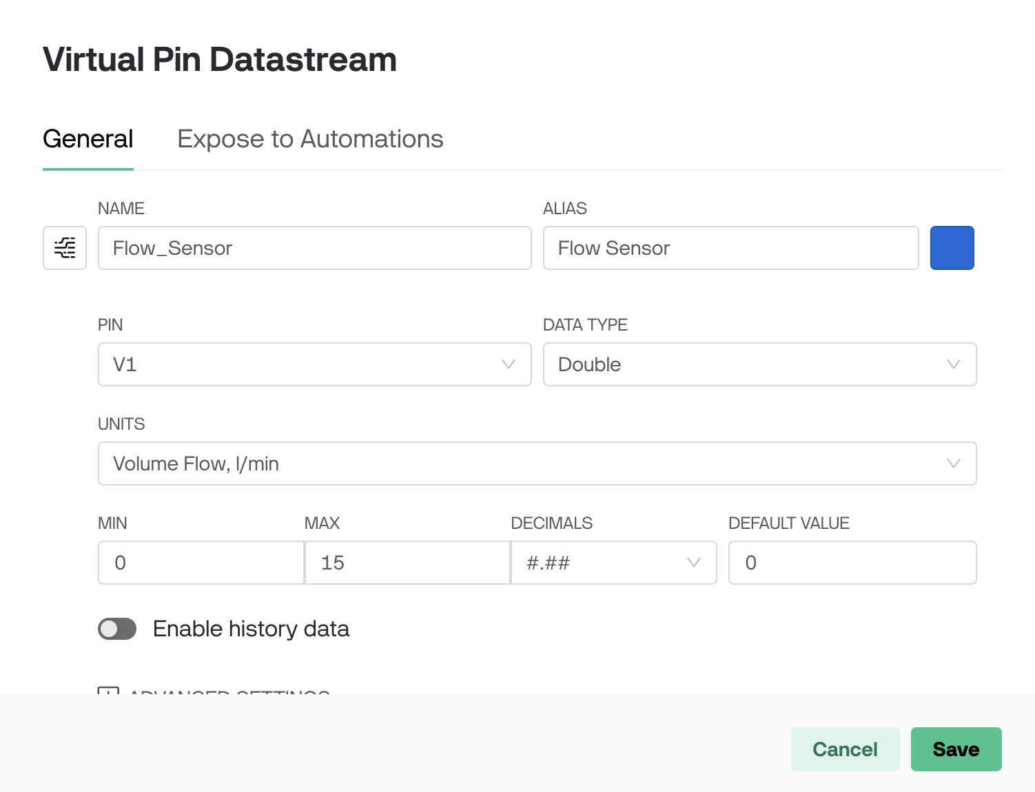
Solenoid up and under were integer, as they are digital values: 1 for ON or 0 for OFF.
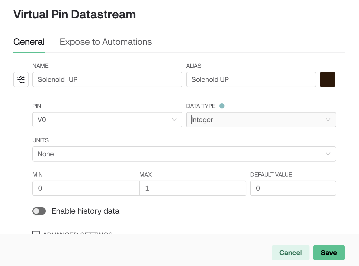
Same for the electric pump: only 2 values (ON of OFF)

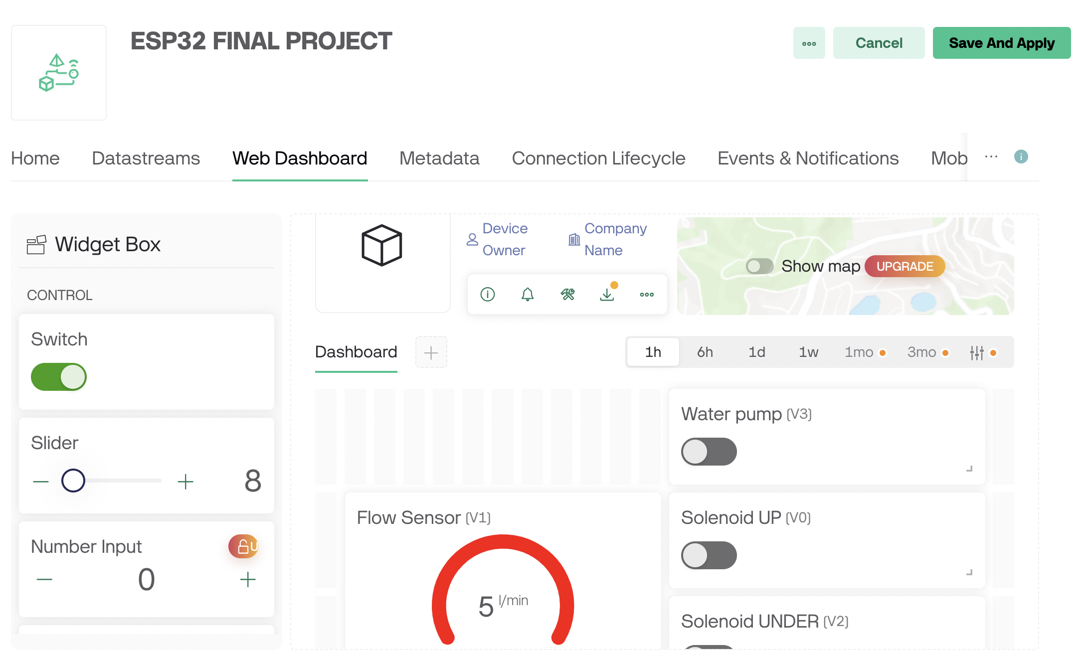
Having defined the variables, I went to my dashboard to configure it and put any graph or switch that I consider appropriate. The graphs will show data in real time, while the switch will allow me to turn the solenoid valves on or off as well as the electro pump. They must be dragged from left to right.
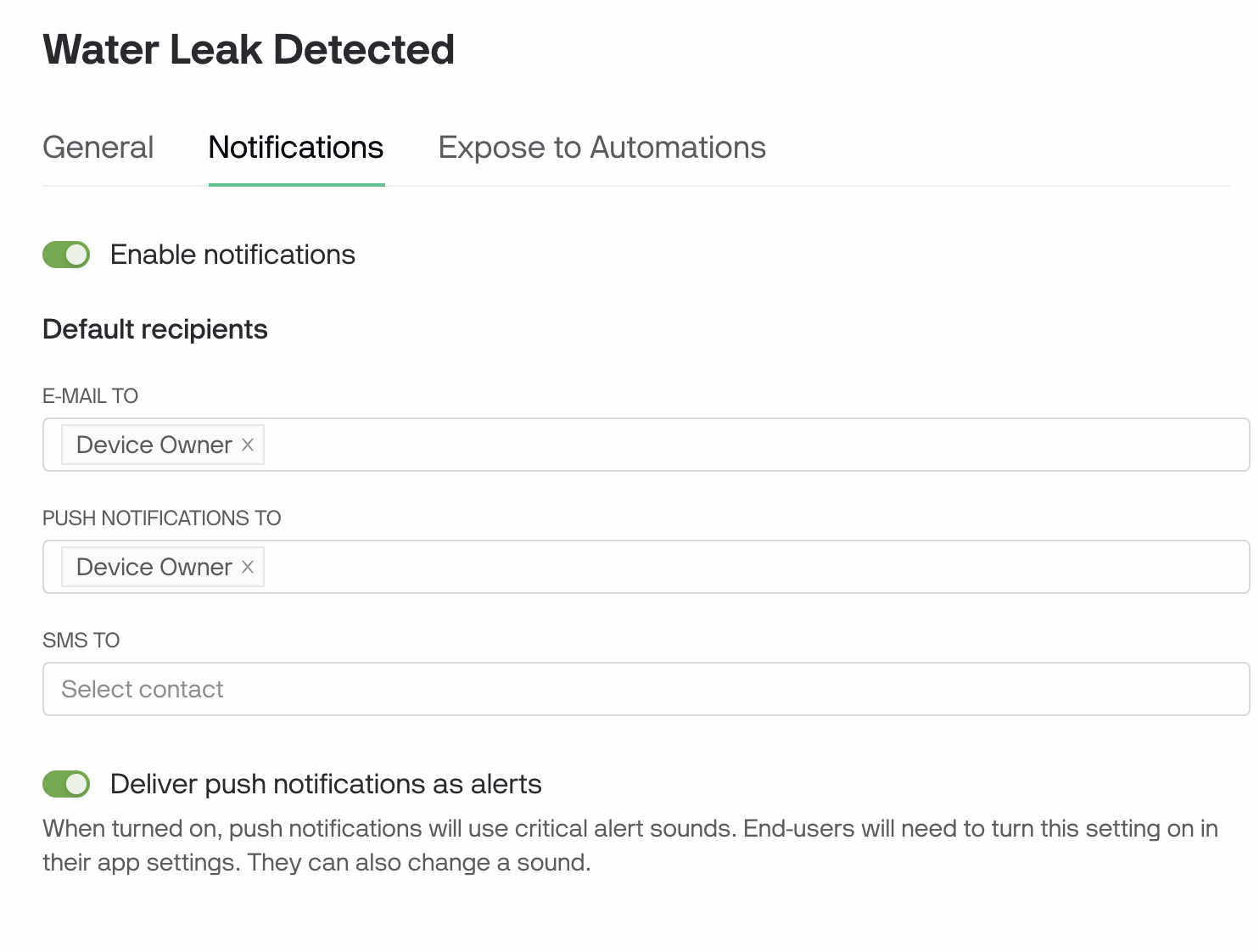
Then create notifications, in the events and notifications tab.
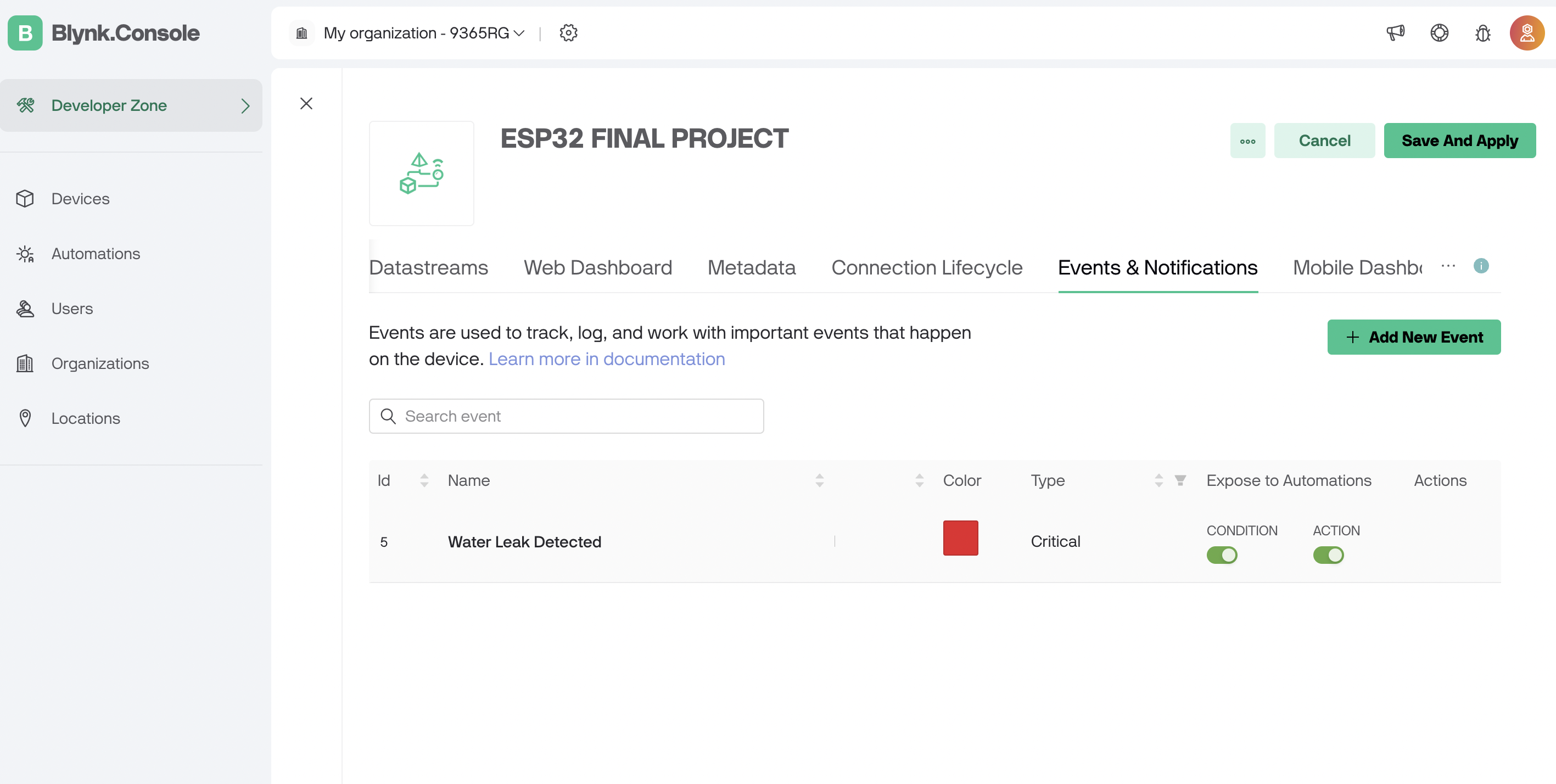
These notifications will be automated, so that when a certain condition is met they will be activated.
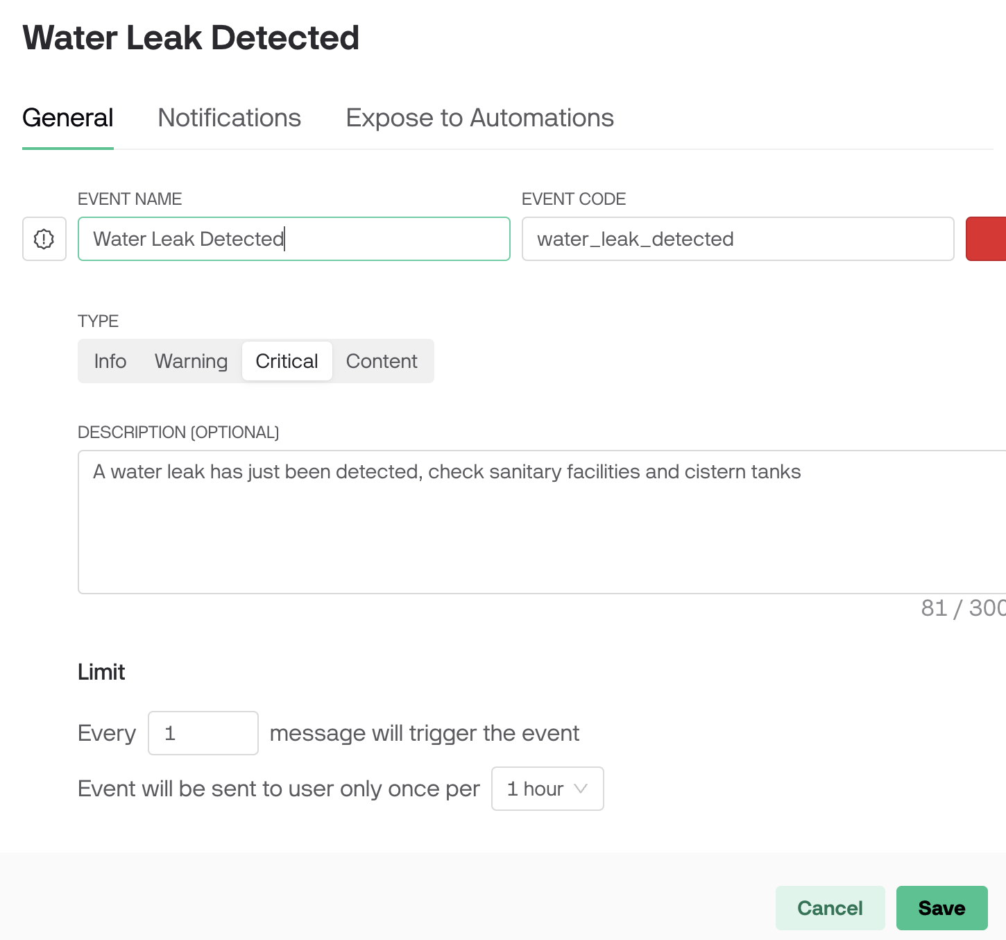
Then in the notifications part, I configured it to notify the user of this account of the alerts that I am going to set later.
Now I go to the option on the left that says "automations" and configure how I want the notifications to be automated, that is, what logic they will have.
The automation seen in the following image corresponds to the fact that if the flow sensor detects any flow greater than 0.1 liters per minute, it will send an alert.
And in addition, I am configuring the behavior of the solenoid valves: the upper one closes at 3:00 am and the lower one opens at that time, circulating the water through the sensor.
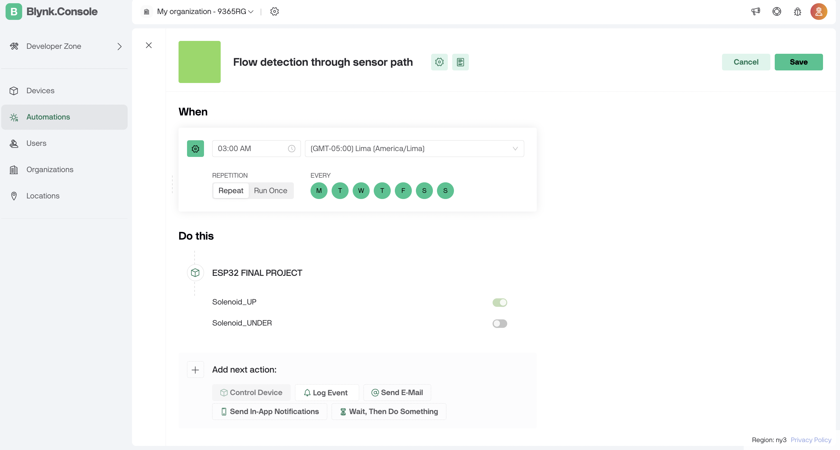
Then, vice versa: at 3:15 the bottom one closes, and the top one opens.
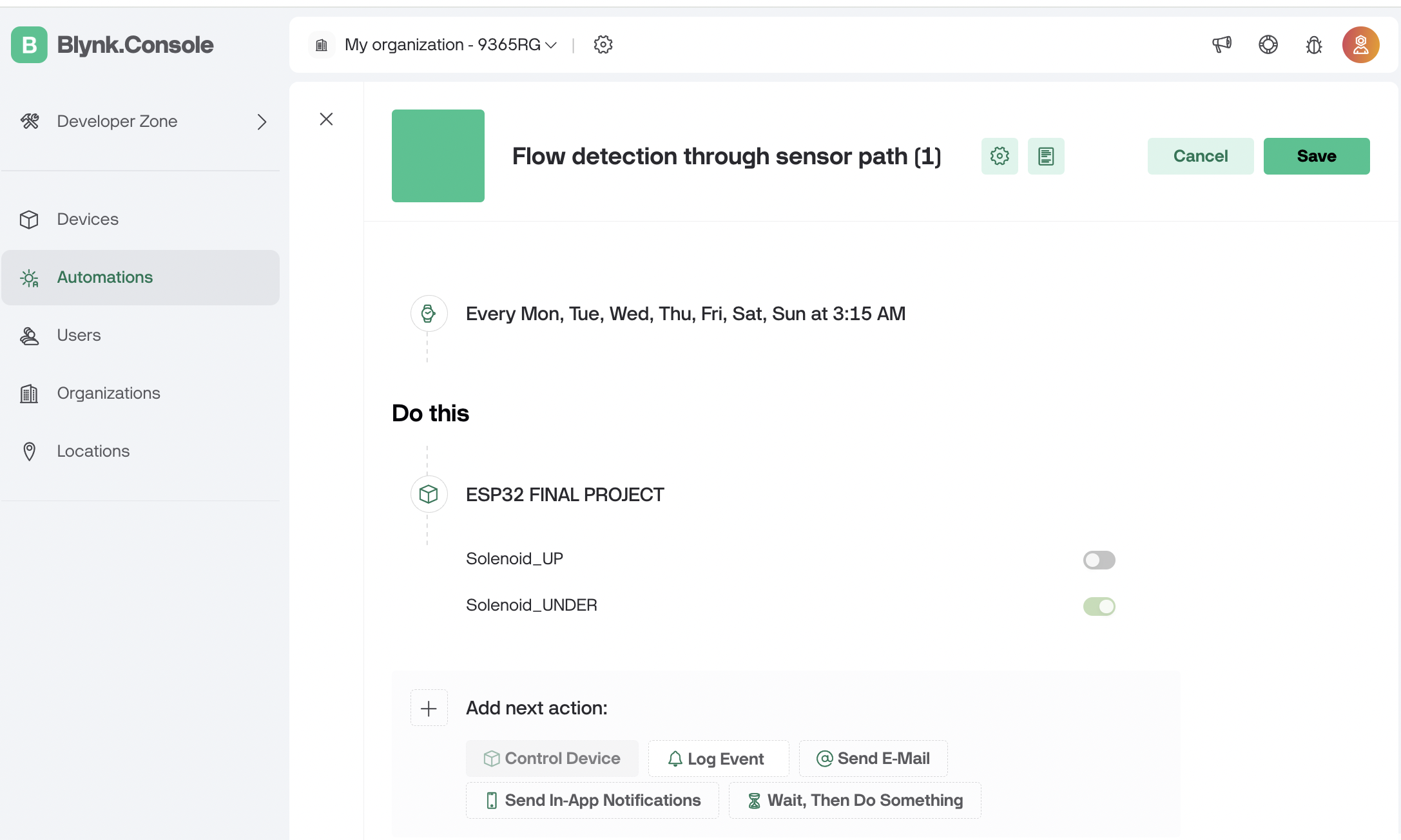
I will be turning the electric pump on manually, and it will always remain in that state. In this way, I am controlling my 3 actuators and my flow sensor, with notifications and operation automations
4. Configure the Blynk Mobile App in the mobile phone:
After downloading the app (can be done on Android and iPhone), I will add widgets so I can control all my devices from my cell phone.
The following photos are cell phone screenshots. Now in the app, I click on the green key button to enter the settings of each element I add.In the photo you can see the elements already added.

Then, the screen will change and you will see dotted grids, this means that we are in editing mode of our menu.
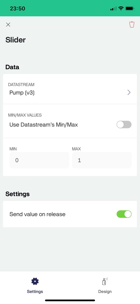
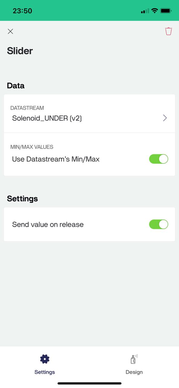
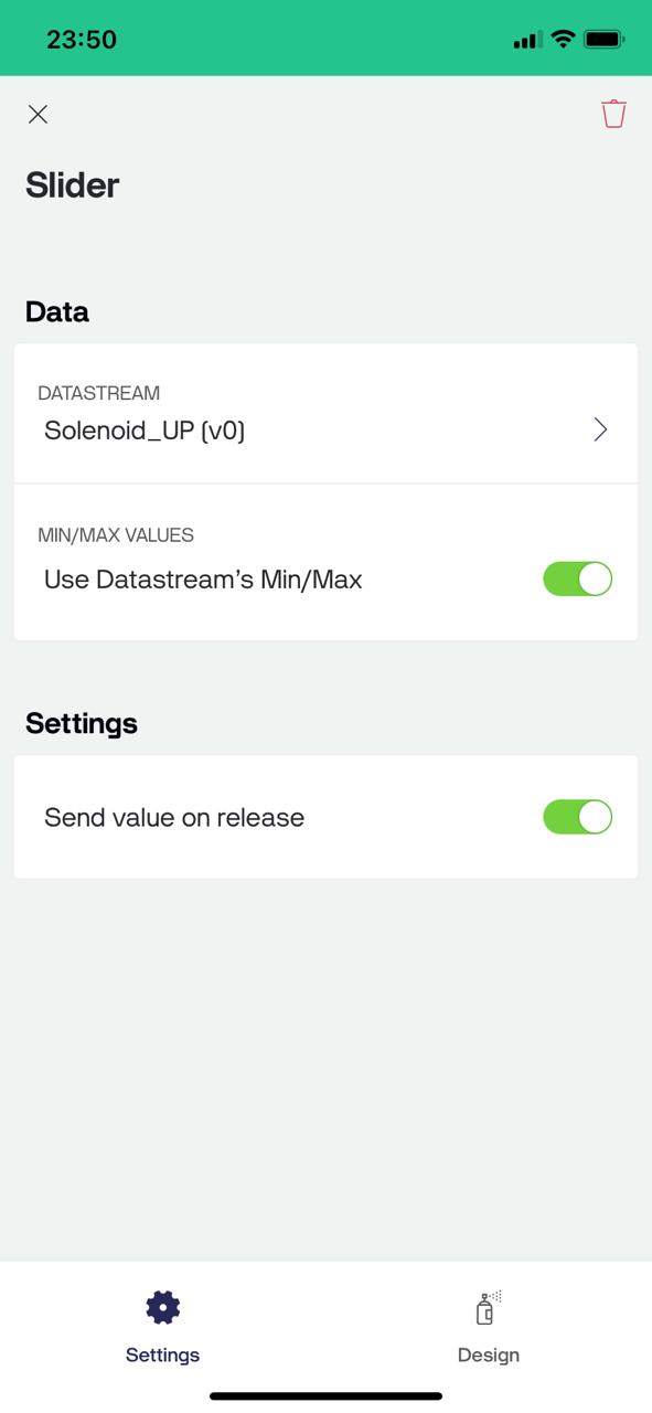
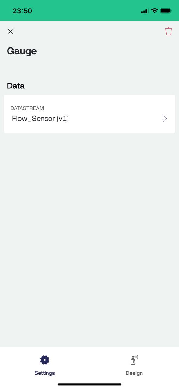
This is where I add 3 sliders (1 for the electric pump, 1 for each solenoid valve), and a gauge to see the flow sensor reading.
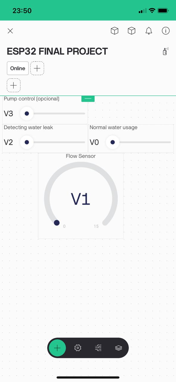
Then, I click on each one of them to assign the Datastream that I had previously configured on the web. I do this for the 4 elements (4 datastreams).
Electric pump:
Solenoid Under:
Solenoid Up:
Flow sensor:
With all this configuration, I will now be able to control these 4 elements from my cell phone. Actually, for my project I will not need to control anything manually since everything was already automated in the previous steps, but there is the option anyway.
5. Write the Arduino Code to Seeeduino Xiao ESP32-C3:
#define BLYNK_TEMPLATE_ID "TMPL2L1JAtM3R" // Define the Blynk template ID
#define BLYNK_TEMPLATE_NAME "ESP32 FINAL PROJECT" // Define the Blynk template name
#define BLYNK_AUTH_TOKEN
"vbwqd0jSgHx8SR12pEOhHkTO03UNKGyk" // Define the Blynk authentication token
#define BLYNK_PRINT Serial // Enable Serial output for debugging
#include #include #include // Your WiFi credentials
char ssid[] = "Depa703"; // SSID where I made my project
char pass[] = "borgono10000"; // Password of the wifi network
// Flow sensor setup
FlowSensor Sensor(150, 8); // Create a flow sensor object with specific parameters
const int solenoidPinUP = 4; // Pin connected to the UP solenoid valve
const int solenoidPinUNDER = 2; // Pin connected to the UNDER solenoid valve
const int mosfetPinPump = 3; // Pin connected to the MOSFET for the pump
// Variables to control the solenoids and the pump from Blynk
bool solenoidUPState = false; // Initial state of the UP solenoid valve
bool solenoidUNDERState = false; // Initial state of the UNDER solenoid valve
bool pumpState = true; // Turn on the pump by default
void count() {
Sensor.count(); // Increment the flow sensor counter
}
void setup() {
// Debug console
Serial.begin(115200); // Initialize the Serial communication at 115200 baud rate
// Connect to Blynk
Blynk.begin(BLYNK_AUTH_TOKEN, ssid, pass); // Connect to Blynk using the authentication token and WiFi credentials
// Initialize the flow sensor
Sensor.begin(count); // Initialize the flow sensor with the count function
// Set the pins as outputs and activate them
pinMode(solenoidPinUP, OUTPUT); // Set the UP solenoid pin as an output
pinMode(solenoidPinUNDER, OUTPUT); // Set the UNDER solenoid pin as an output
pinMode(mosfetPinPump, OUTPUT); // Set the MOSFET pump pin as an output
// Turn on the pump at the start
digitalWrite(mosfetPinPump, HIGH); // Turn on the pump by setting the pin HIGH
}
// Blynk functions to handle the solenoid and pump switches
BLYNK_WRITE(V0) {
solenoidUPState = param.asInt(); // Get the value from the Blynk app for the UP solenoid
digitalWrite(solenoidPinUP, solenoidUPState); // Set the UP solenoid state
Blynk.virtualWrite(V0, solenoidUPState); // Update the switch state in the Blynk dashboard
}
BLYNK_WRITE(V2) {
solenoidUNDERState = param.asInt(); // Get the value from the Blynk app for the UNDER solenoid
digitalWrite(solenoidPinUNDER, solenoidUNDERState); // Set the UNDER solenoid state
Blynk.virtualWrite(V2, solenoidUNDERState); // Update the switch state in the Blynk dashboard
}
BLYNK_WRITE(V3) {
pumpState = param.asInt(); // Get the value from the Blynk app for the pump
digitalWrite(mosfetPinPump, pumpState); // Set the pump state
Blynk.virtualWrite(V3, pumpState); // Update the switch state in the Blynk dashboard
}
void loop() {
Blynk.run(); // Run the Blynk main loop
}
The following diagram shows the flow of information from the blynk app to the actuators.
The following video demonstrates how I control the electric pump using the Blynk interface on my cellphone:
In this group part I learned how the MIT Inventor interface works. I also learned from other programming environments, where there are specialized software for each topic. Until now I knew Mit Inventor with Bluetooth working functionality, but there are others as listed on the group page.
My contribution to this week's group work was to find information and characteristics of the operation of the Blynk application, for IoT connectivity.
Here is the link to the group assignments:
Files:
6. Test the Project:
I Used the widgets I configured to control the electric pump, 2 solenoids and read the flow sensor.
Group assignment