Assignments
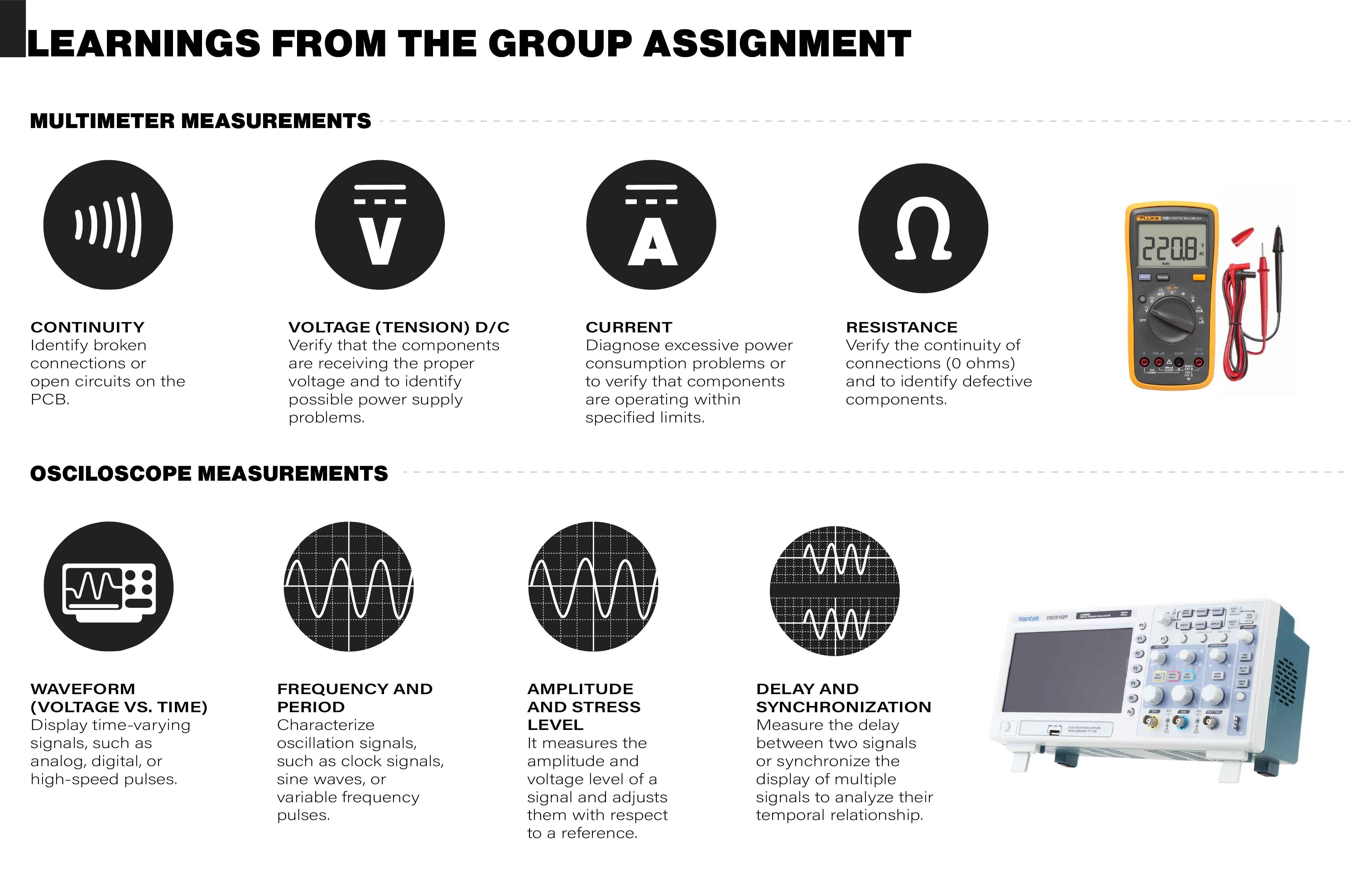
- Use the test equipment in your lab to observe the operation of a microcontroller circuit board (as a minimum, you should demonstrate the use of a multimeter and oscilloscope).
- Document your work on the group work page and reflect what you learned on your individual page.
Individual apport
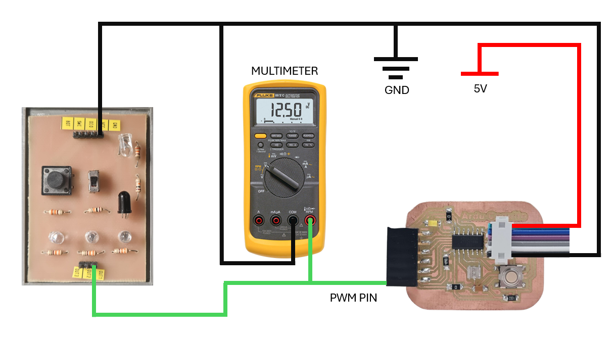
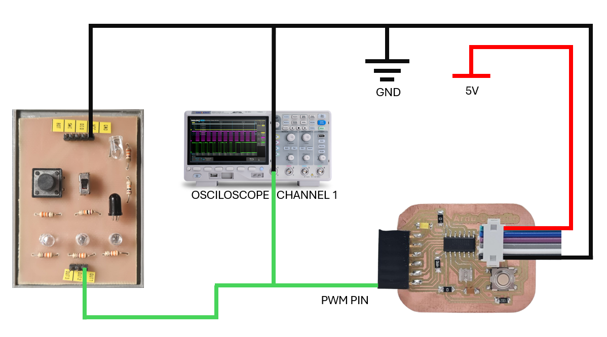
- Ernesto, Jorge, Marcela: Our contribution to the group project involved measuring PWM signals (both constant and variable) with an oscilloscope, and measuring power consumption using a multimeter in a circuit that included a blinking LED.
Operation of a Microcontroller Circuit Board (Attiny44):
This week's assignment involved using lab equipment to observe the operation of a microcontroller circuit board, specifically focusing on demonstrating the use of a multimeter and oscilloscope. We programmed an ATtiny44 microcontroller to control an LED, starting with a simple digital signal to blink the LED. Following this, we created code to turn the LED on at a constant 100 PWM, and then incrementally increase the PWM in steps of 10 until reaching 250 PWM. The primary objective was to measure the digital/analog output of the microcontroller using an oscilloscope, allowing us to observe the behavior of the signals generated by the ATtiny44.
Multimeter Connection Diagram:
Osciloscope Connection Diagram:
Digital Signals:
ARDUINO CODE (Digital Blink):
// the setup function runs once when you press reset or power the board
void setup() {
  // initialize digital pin LED as an output.
  pinMode(7, OUTPUT);
}

// the loop function runs over and over again forever
void loop() {
  digitalWrite(7, HIGH);
  delay(2000);  // Wait for 2 seconds
  digitalWrite(7, LOW);
  delay(2000);  // Wait for 2 seconds
}
MULTIMETER TEST (Digital Blink):
OSCILOSCOPE TEST (Digital Blink):
Analog Signals:
ARDUINO CODE (Constant PWM):
// the setup function runs once when you press reset or power the board
void setup() {
  // initialize digital pin LED as an output.
  pinMode(7, OUTPUT);
}

// the loop function runs over and over again forever
void loop() {
  analogWrite(7, 100);  // PWM(0-255)
}
OSCILOSCOPE TEST (Constant PWM):
ARDUINO CODE (Variable PWM):
// the setup function runs once when you press reset or power the board
void setup() {
  // initialize digital pin LED as an output.
  pinMode(7, OUTPUT);
}

// the loop function runs over and over again forever
void loop() {
  // Increment the PWM value from 10 to 250 in steps of 10
  for (int pwmValue = 10; pwmValue <= 250; pwmValue += 10) {
    analogWrite(7, pwmValue);  // Set the PWM value
    delay(1000);  // Wait for a second
  }
}
OSCILOSCOPE TEST (Variable PWM):