10 - 11. Mechanical & Machine Design - Break and midterm
These two weeks we have simple individual assignment: documented our contribution to the group assignment. This group assignment is the most demanding of the entire Fab Academy: the design and construction of an automated motion machine. After our class sessions we decided to meet at lunchtime to decide what our project would be. The final result can be found here.
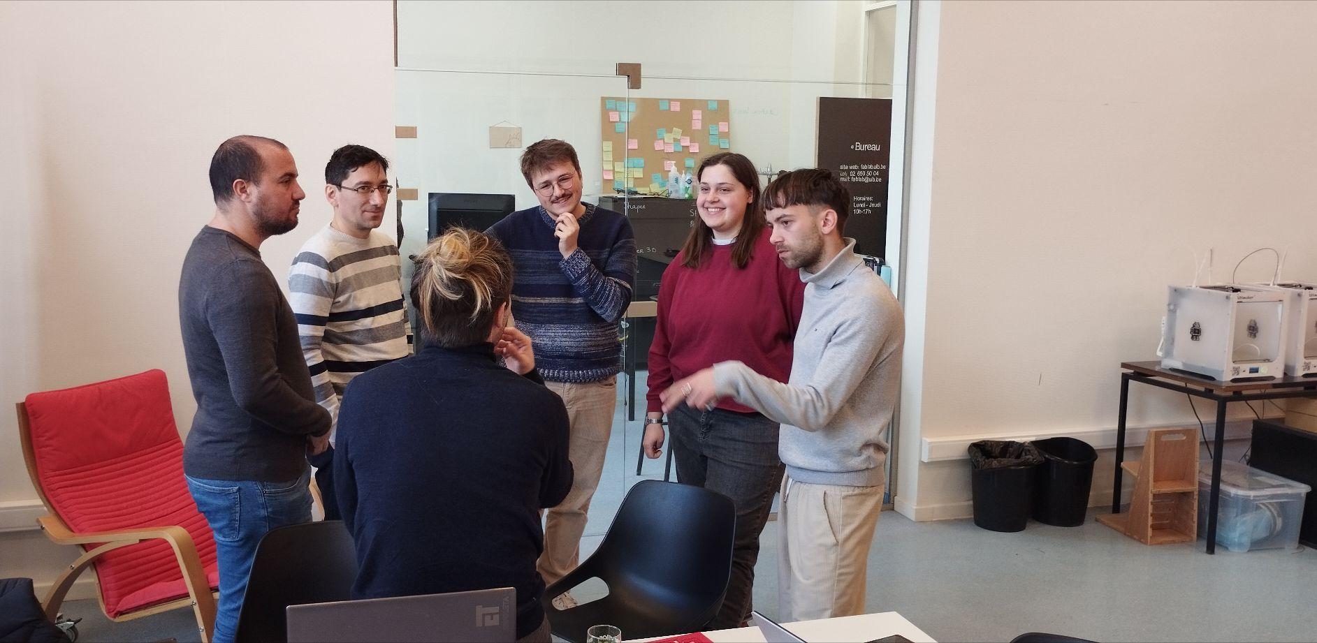
Inicial meeting
After an intense and productive meeting, we decided that our biweekly project would be a variant of the Urumbu Machine, transformed into a drawing machine. In addition, we made the distribution of the tasks to be performed by each one, as shown in the following table:
| Function | Development | Who |
|---|---|---|
| 2D Axis System | Mechanical | Teo & Charlotte |
| Electronic | Bogdan & Alex | |
| Software | Siméon | |
| Modular Tool Head | Mechanical | Luis Abel (me) |
| Electronic | Alex | |
| Software | Siméon |
As can be appreciate, my fundamental apport to the project is the design and construction of the mechanical part of the Modular Tool Head. That has a critical inconvenient: I had to wait for the electronic design to be ready to take it into consideration in my design.
To start with I started looking for different variants of effectors already created on Thingiverse for 4xiDraw drawing machines. Finally I decided to start from the designs offered by the designer MiguelBi with his variant of 4xiDraw drawing machine, called AXIDRAW Clone. The following image shows the used parts of this design.
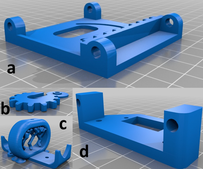
Parts used to make our effector
For our effector we maintained parts b and c of the previous figure unaltered, while parts a and d were modified.
The .stl files are not easy to modify and many of the operations that would commonly be done in FreeCAD give an error. But there is an alternative to this problem. FreeCAD's Part Workbench has a tool for creating shapes from meshes, as shown in the figure.
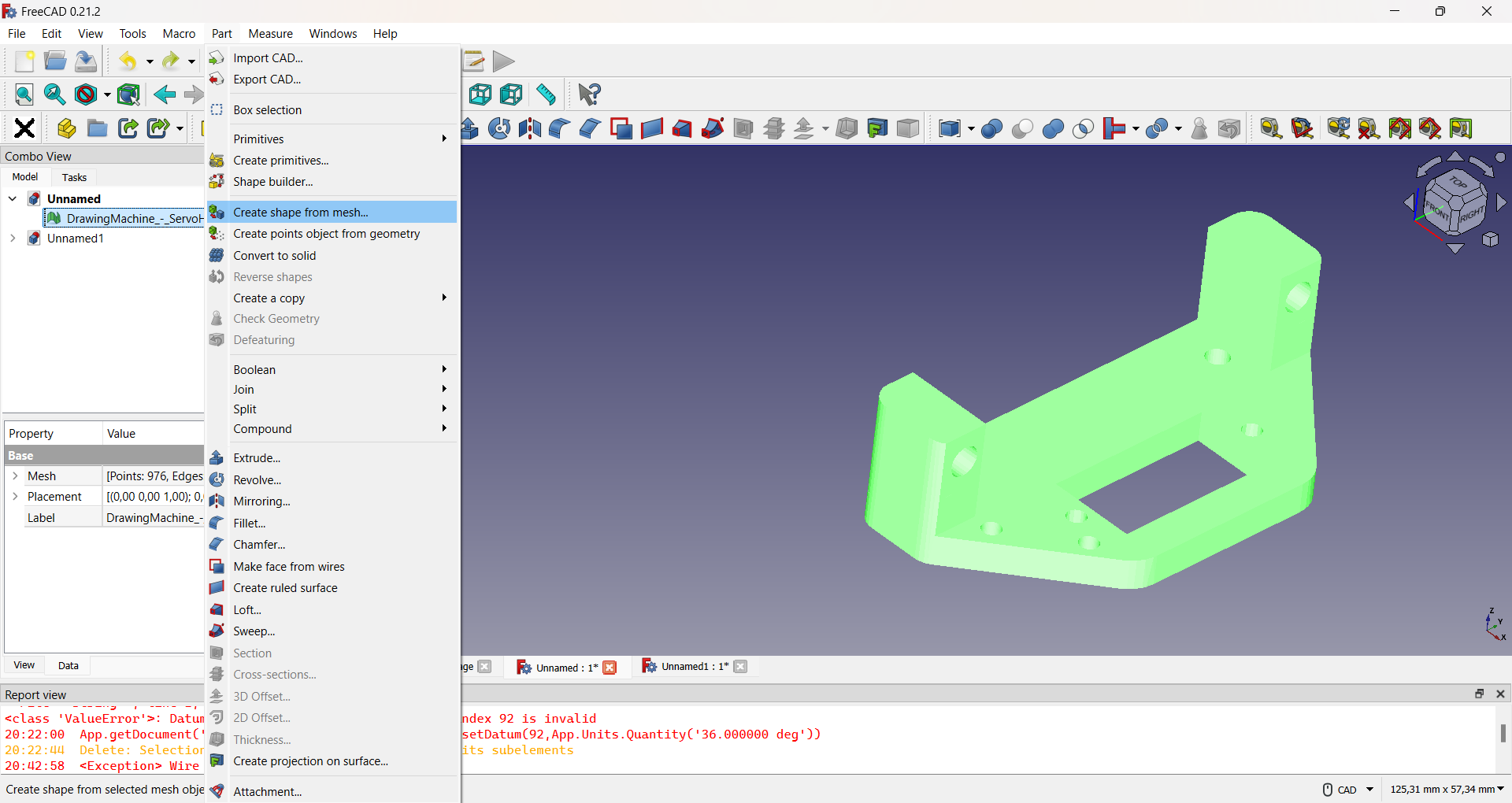
Sellecting the object and the command used.
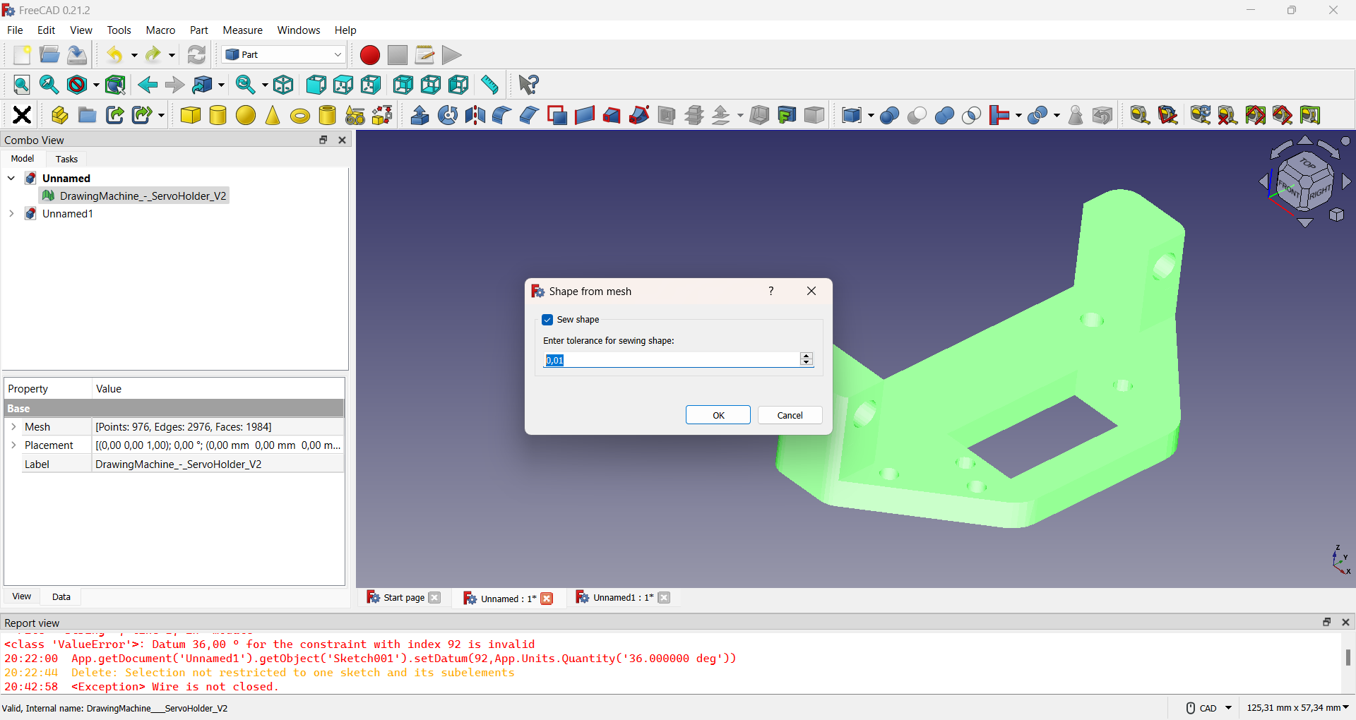
Sellecting the tolerance.
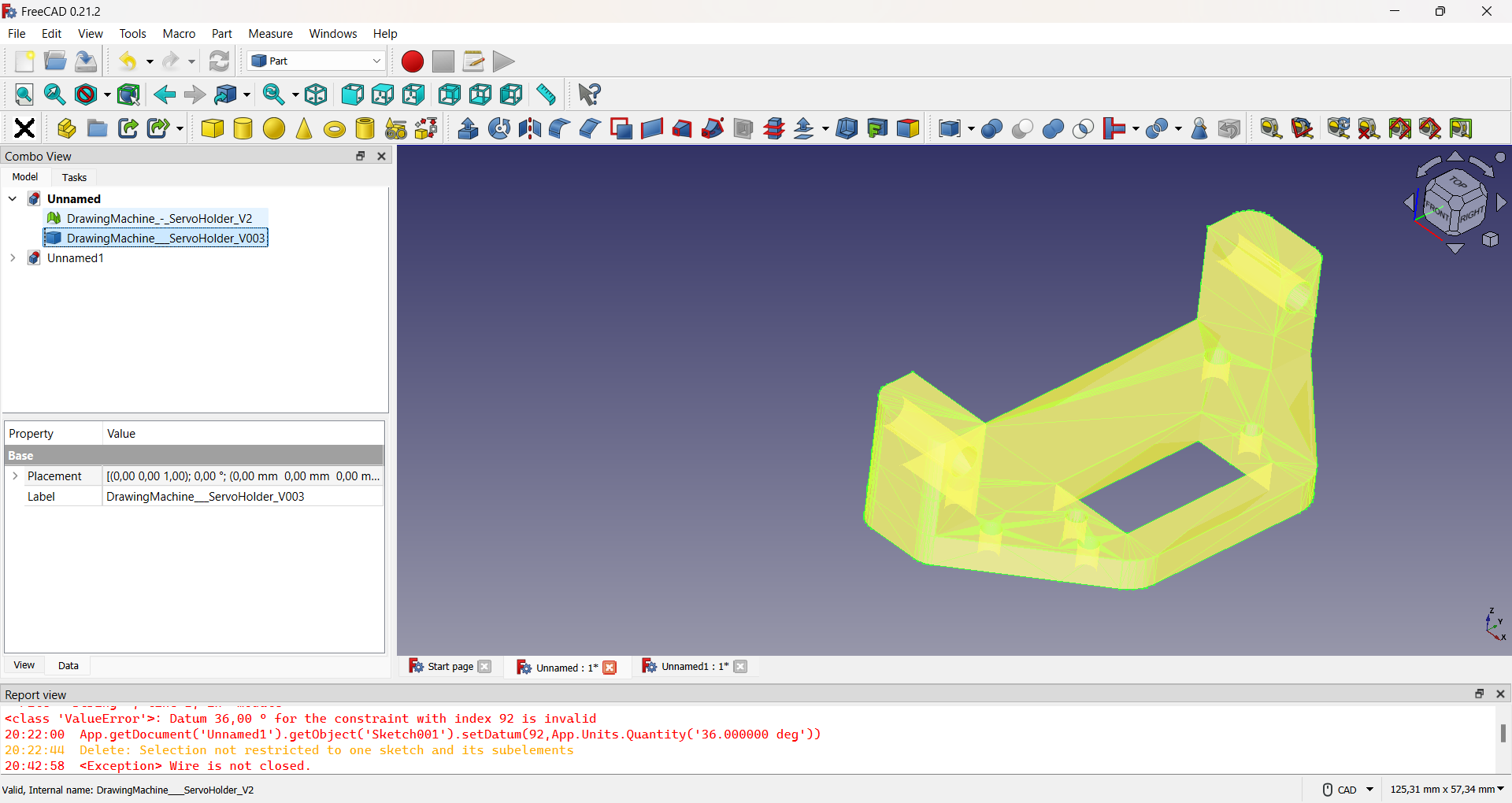
A first view of the mesh created.
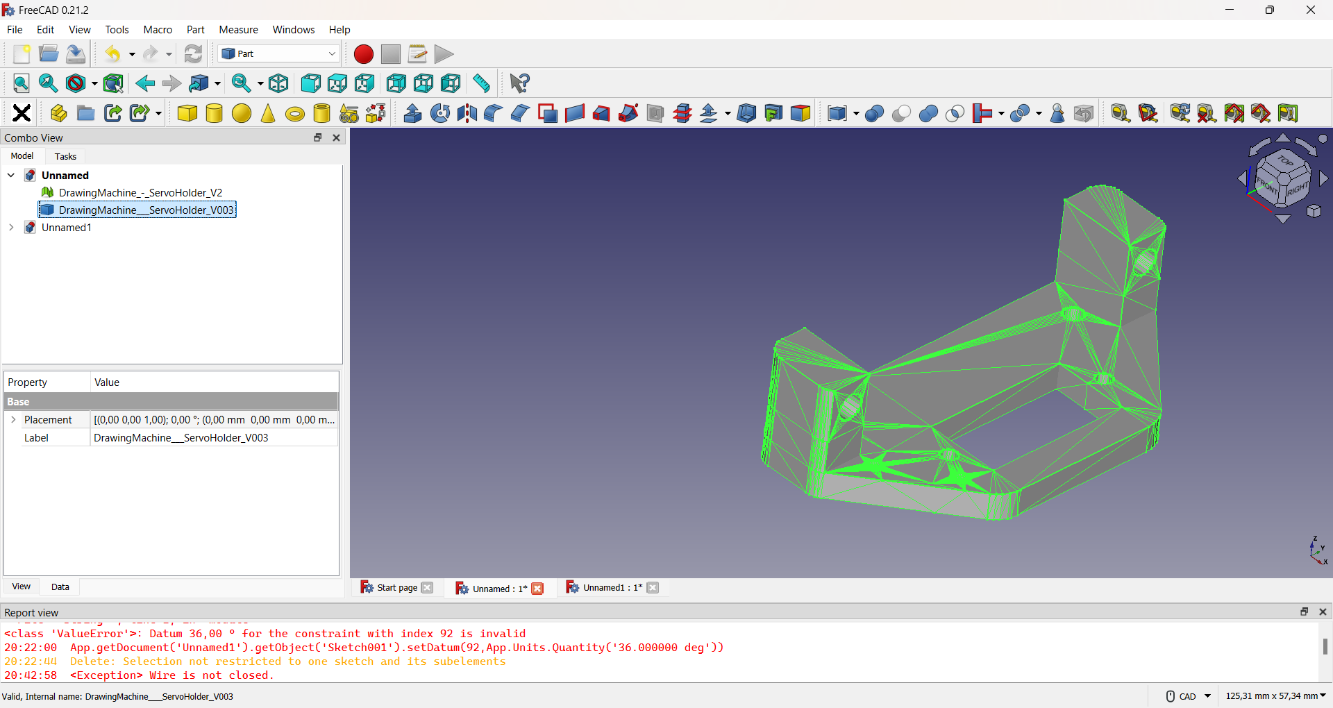
A second view of the mesh created.
Then we create a solid from the mesh obtained, as shown in the figure.
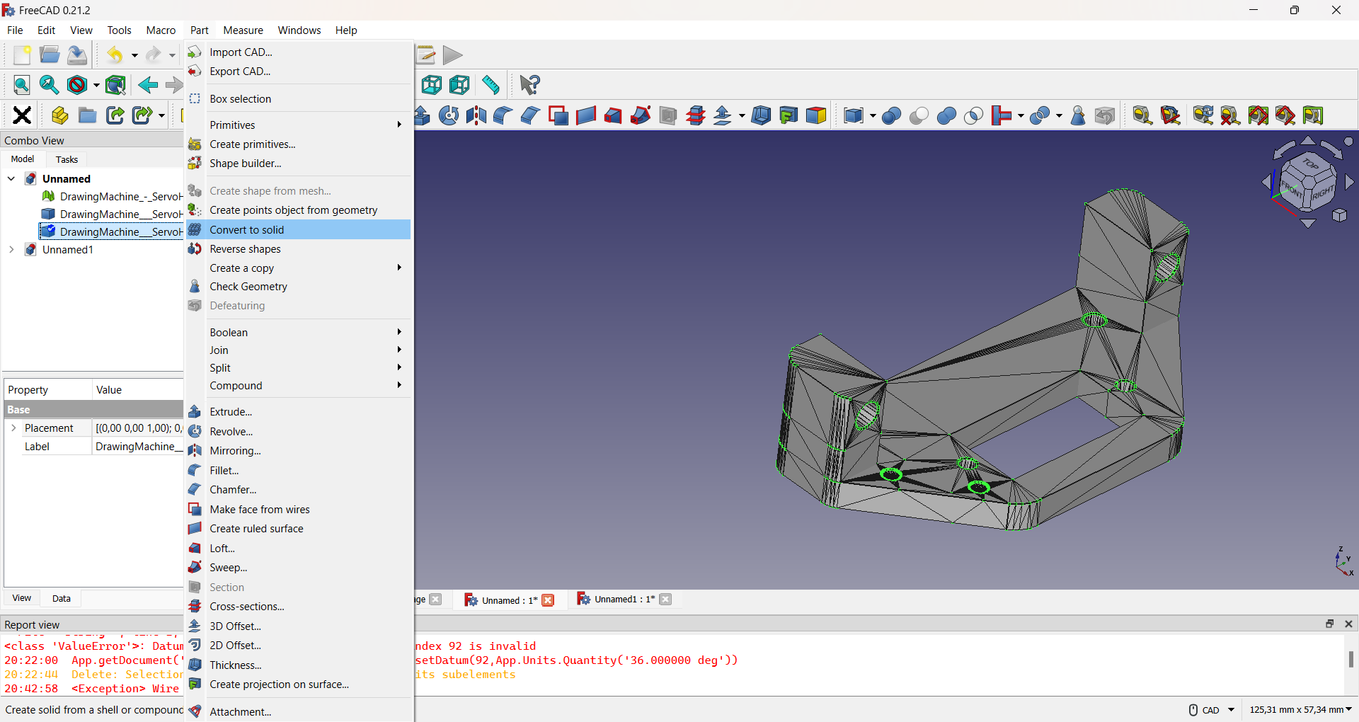
Sellecting the object and the command used.
The same procedure was applied to the other part, in order to convert them into modifiable objects in FreeCAD. Subsequently, the parts shown in the figure were added to hold the servomotor board and attach the effector to the machine platform.
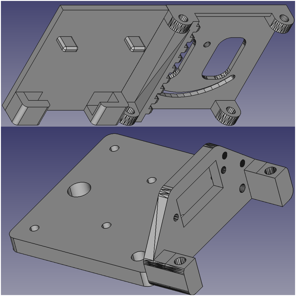
Both pieces are already modified.
The following image show the pieces 3D printed and assembled:

Different views of the effector.
Hero shot
