7. Computer-Controlled Machining
The primary goal this week was to design, mill, and assemble a one-meter scale part. As an additional challenge, we were tasked with assembling the part without the use of fasteners or glue, and incorporating curved surfaces. I was only able to fulfill the first extra credit requirement.
Computer Numerical Control (CNC) cutting is an automated manufacturing process that utilizes computer-controlled machines to cut materials such as metal, wood, or plastic with high precision and repeatability. Its main features include high precision, the ability to produce complex parts, and efficiency in mass production. This method is utilized in a variety of industries, including automotive, aerospace, construction, and tool manufacturing, to produce customized and mass-produced parts with high-quality finishes.
Research
The group assignment can be found here.
This week, I designed and built a children's chair for my son. To find inspiration, I searched various sites such as Pinterest Mexico, Pinterest Spain, Thingiverse, and Etsy. After exploring different options, I created a final design consisting of four pieces that artfully assemble without the use of fasteners or glue. I am excited to see my son's reaction when he tests the chair, even if I have to wait until July.
After analyzing different models I started to design the chair in FreeCAD. It will consist of four pieces: the back part, the sitting part and the sides, the latter being identical pieces.
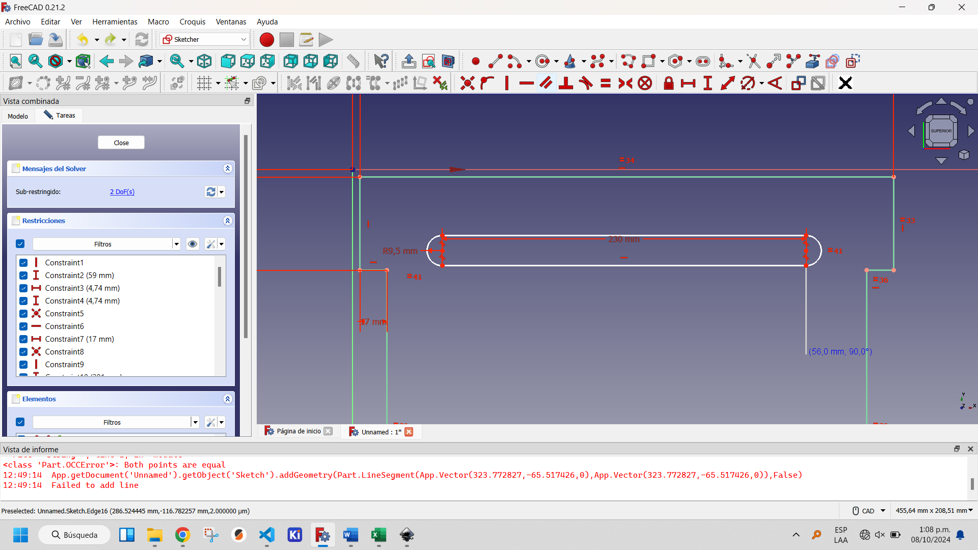
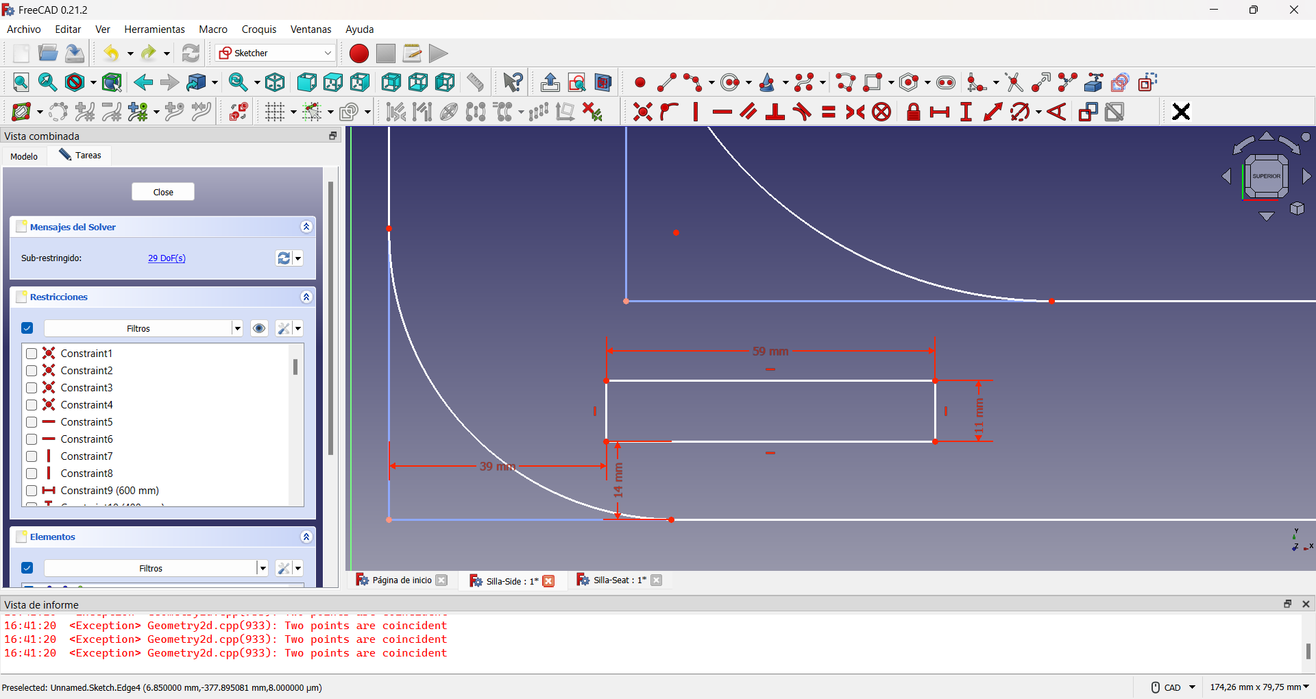
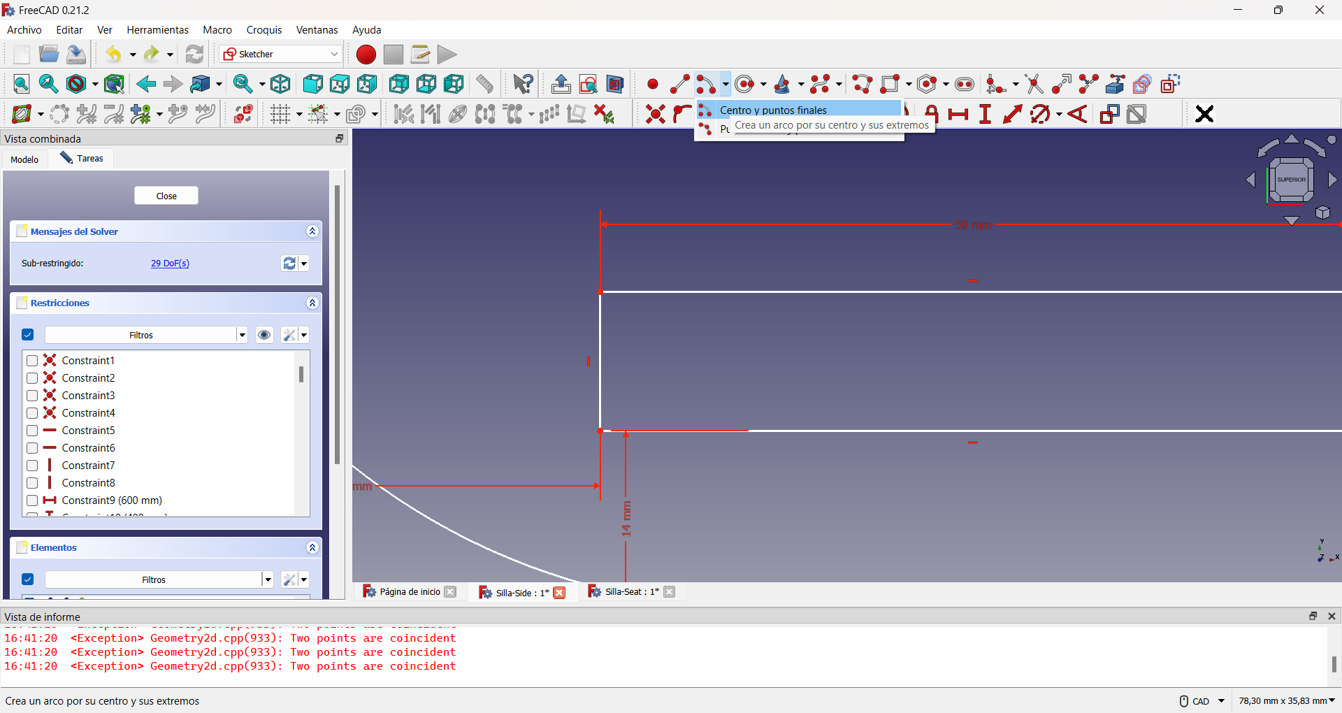
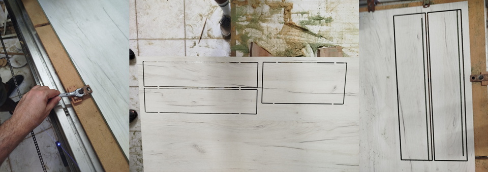
For the design of the back part I realized that I only need to take four different distances and the rest are obtained by establishing equalities between the segments, as can be seen in the following figures:
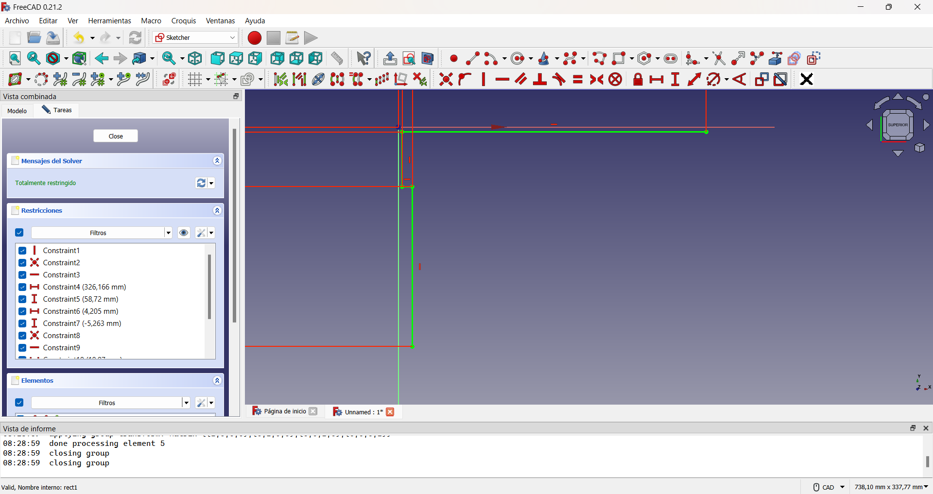
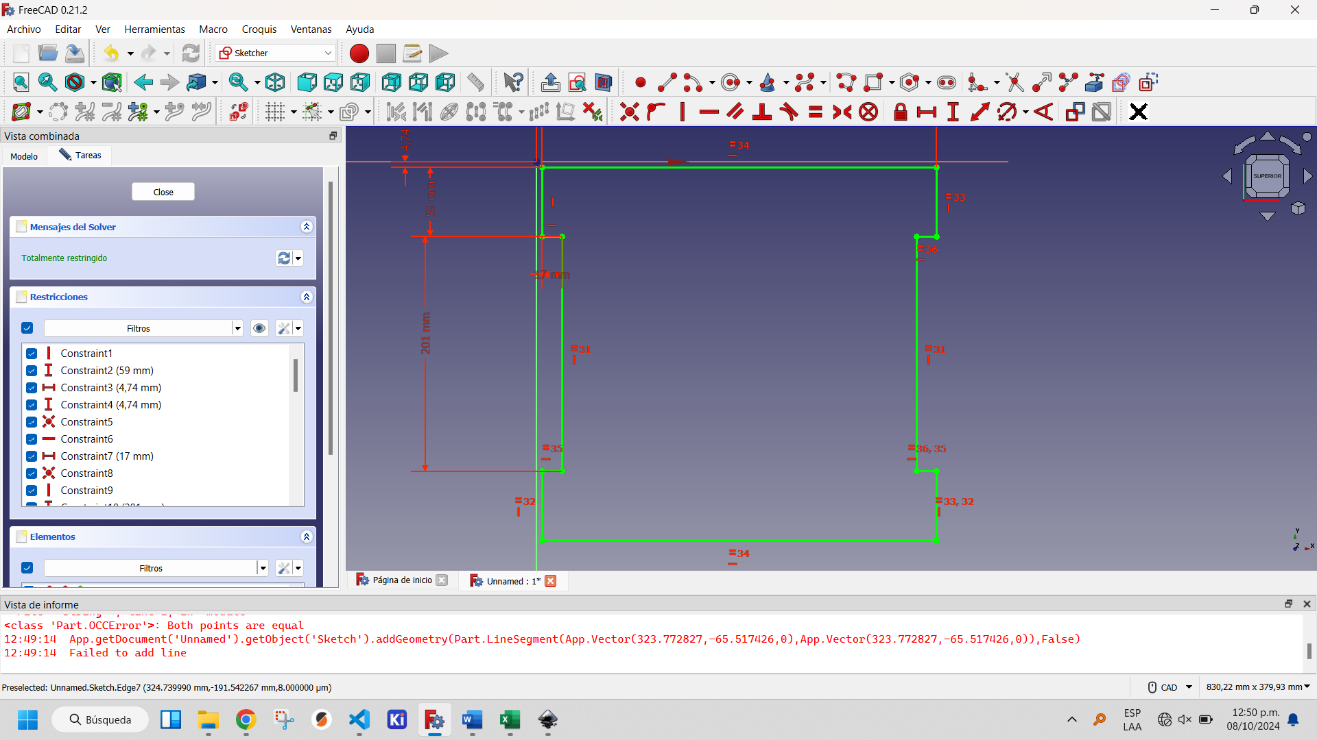
Initial lines to build the chair backrest seal.
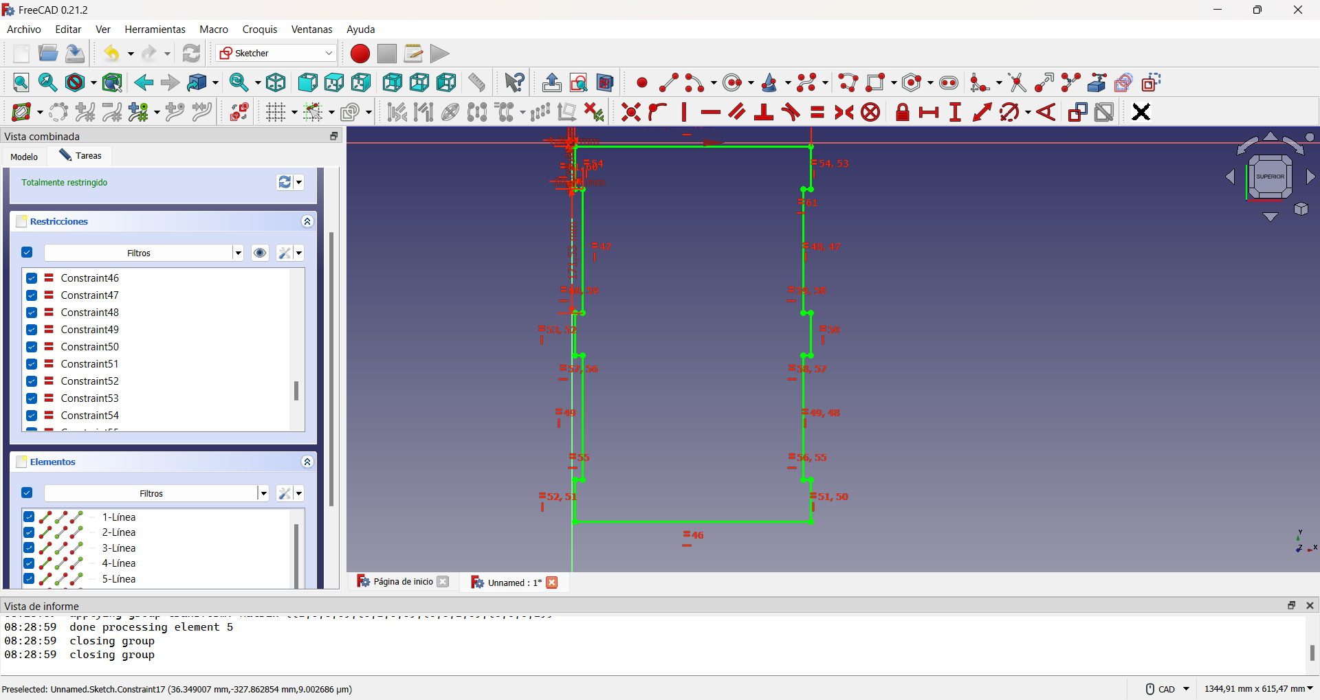
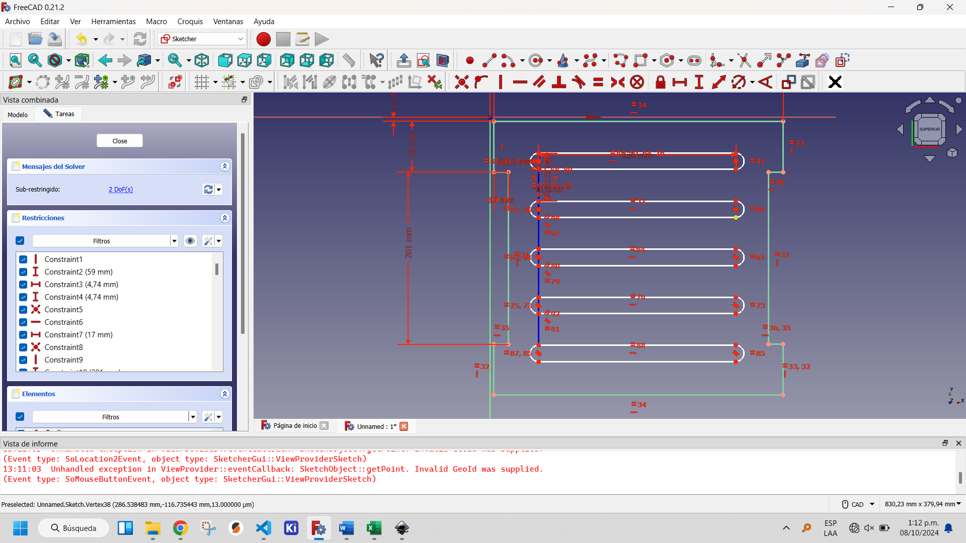
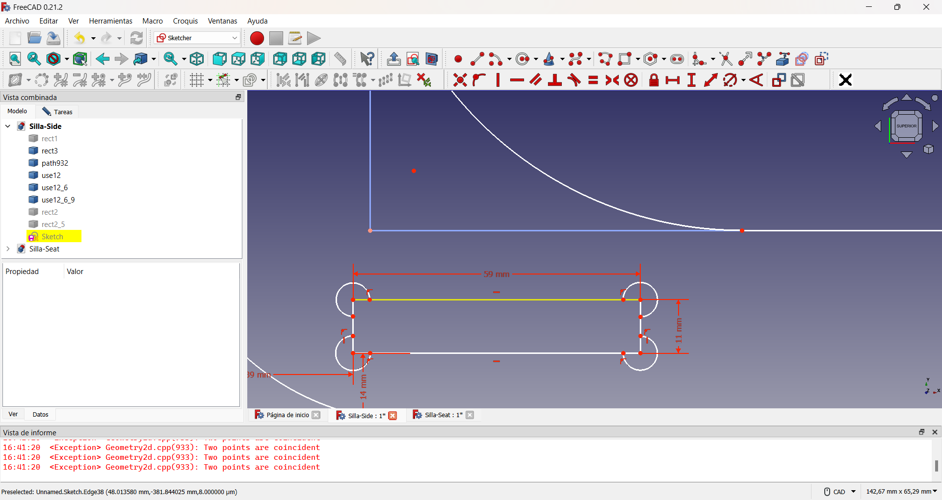
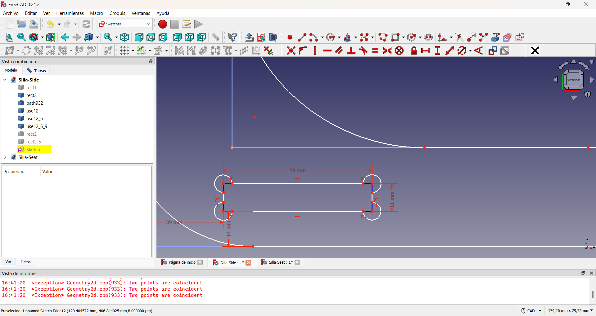
Chair back design. As the design is fully restrained, the color of the lines changes.
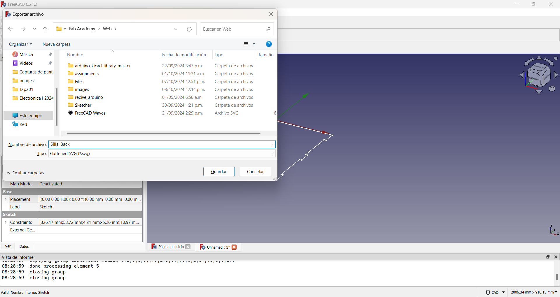
By pressing the keys Ctrl+E we can export the file. In my case in .svg to be used by the CNC, as shown in the figure.
The seat part of the chair was also made in FreeCAD. Like the back part, it is made up of four pattern lines for the edge, as shown in the figure.

Applying the procedure described above for the backrest, the entire edge of the seat is constructed.
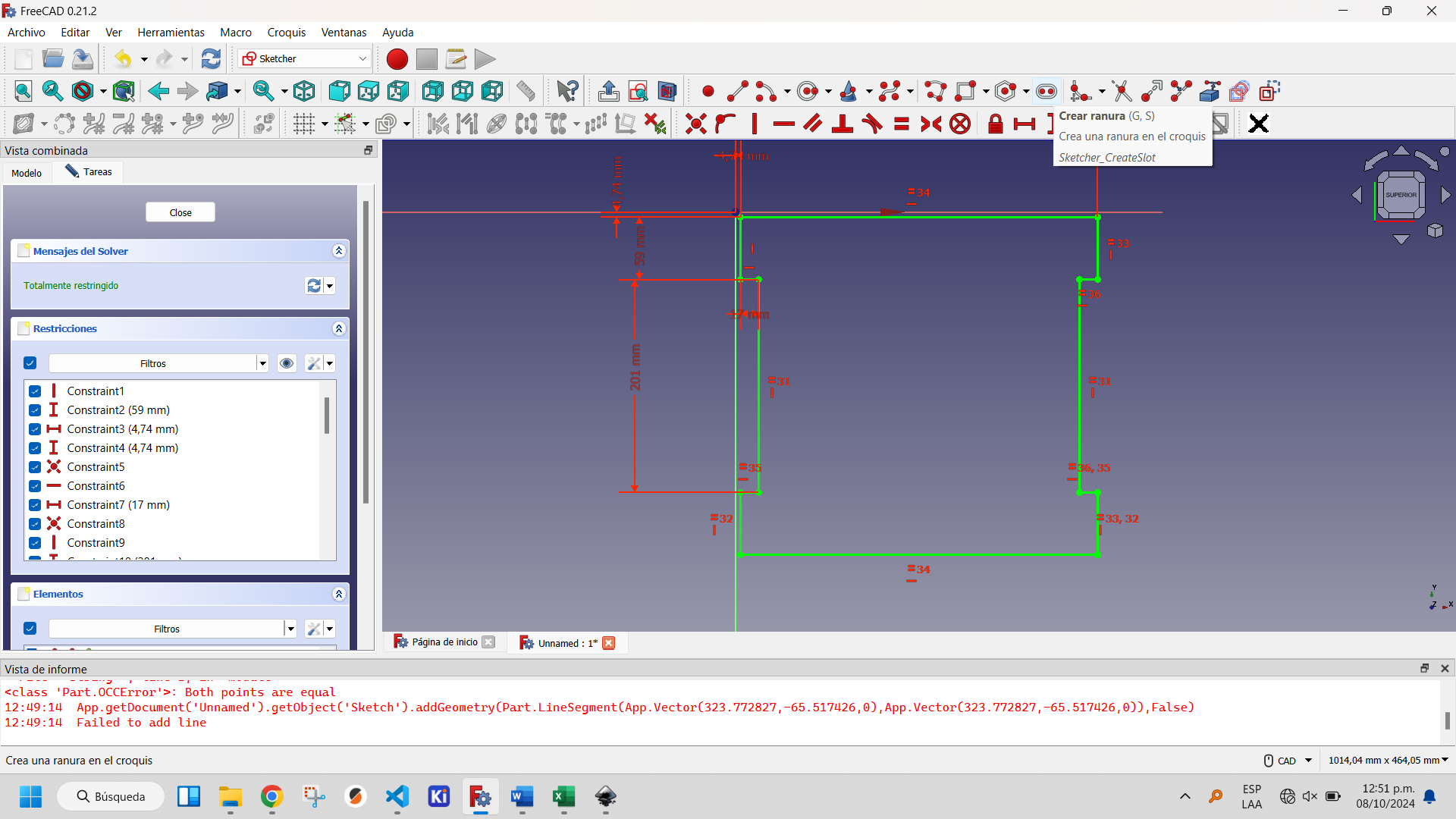
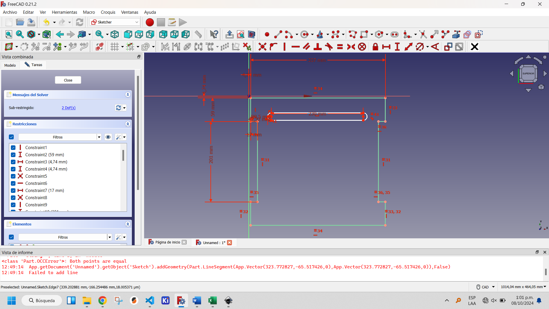
To complete the design of the seat of the chair I decided to place some openings that facilitate ventilation and serve as support places when you want to move the chair. For this I used the slot tool of Sketcher Workbench of FreeCAD, as you can see in the following images.
Selecting the created slot activates the buttons on the Sketcher Tools, within which two options appear that allow you to replicate created objects: Clone and Rectangular Array. The first one creates a copy of the object, the second one a matrix of objects. The latter is the optimal one to use in this case to create an array of one column and five rows. This is shown in the following figures.
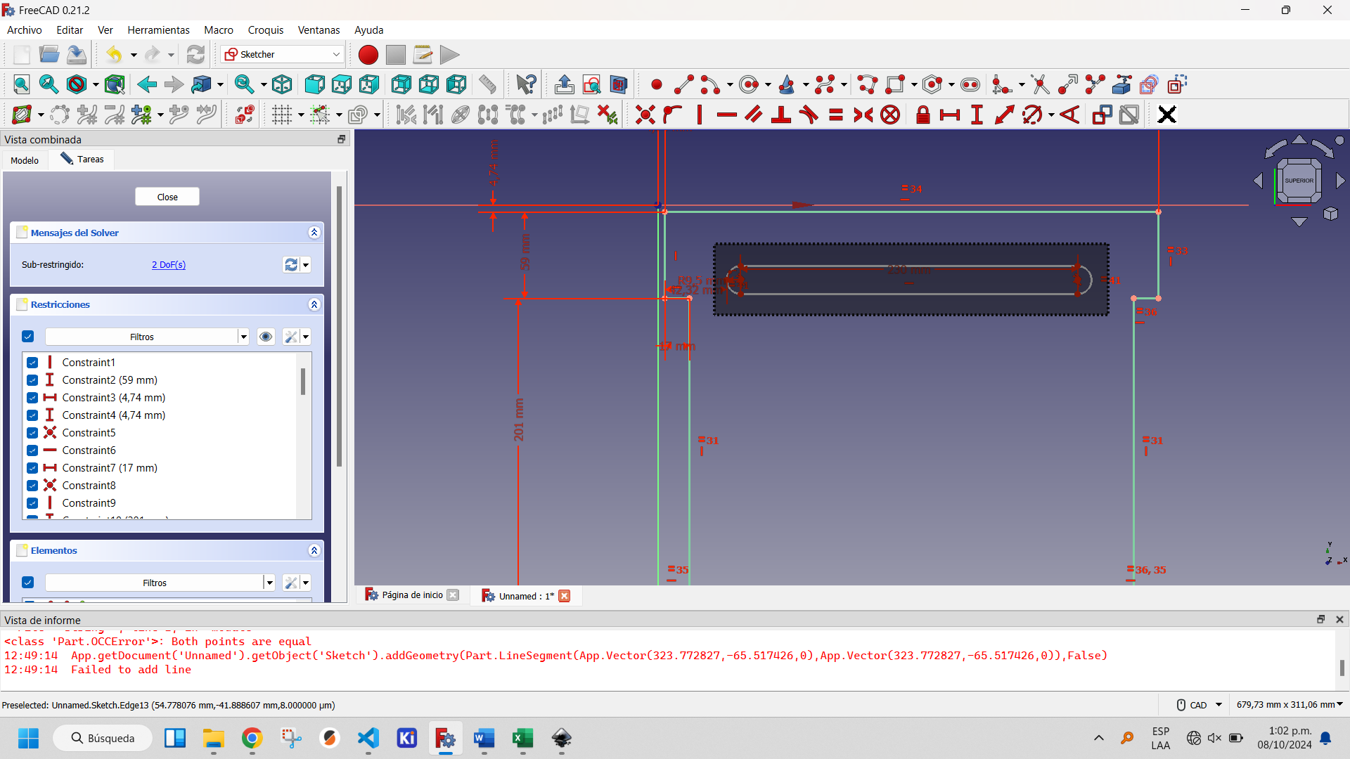
Selecting all the parts of the created slot.
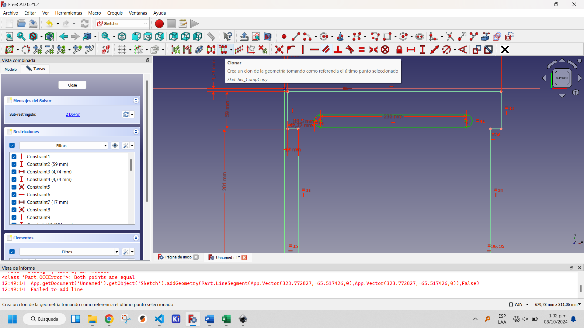
Showing the clone tool button.
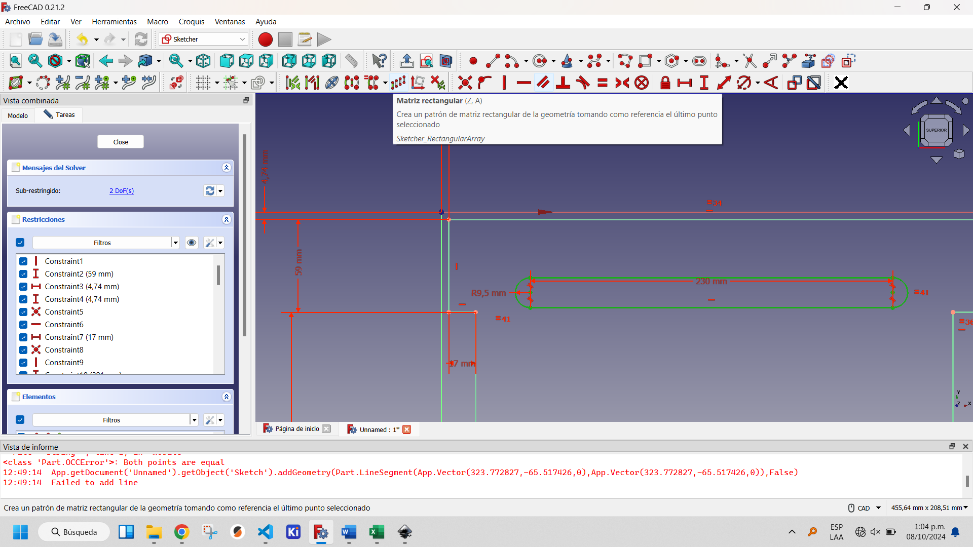
Showing the rectangular matrix tool button.
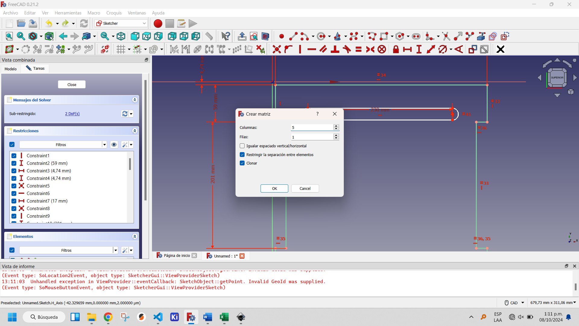
Creating a rectangular matrix of the slots: step 1.
Creating a rectangular matrix of the slots: step 2.
Showing the rectangular matrix of the slots created.
Finally we export the sketch to an .svg file, as shown above.
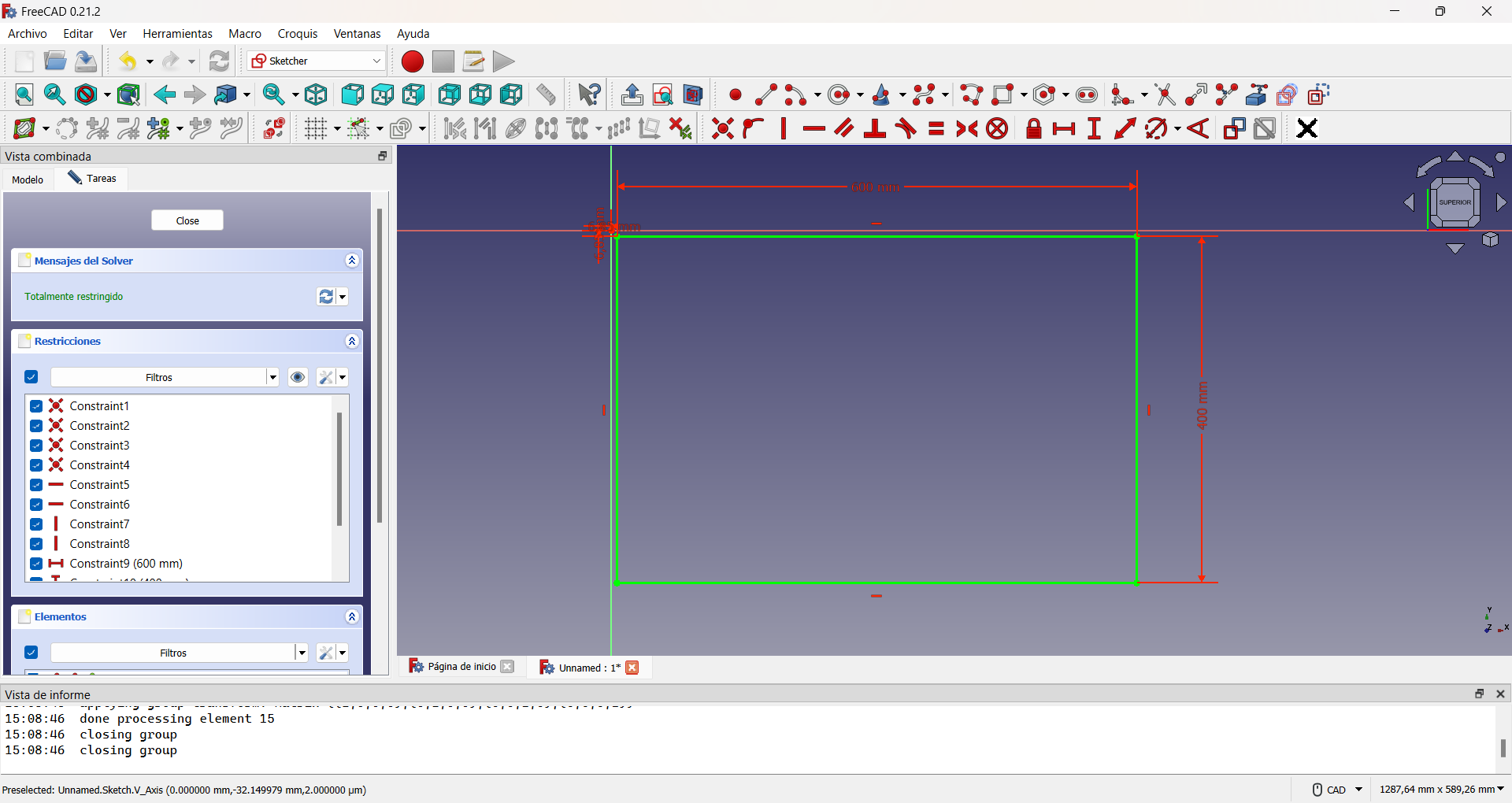
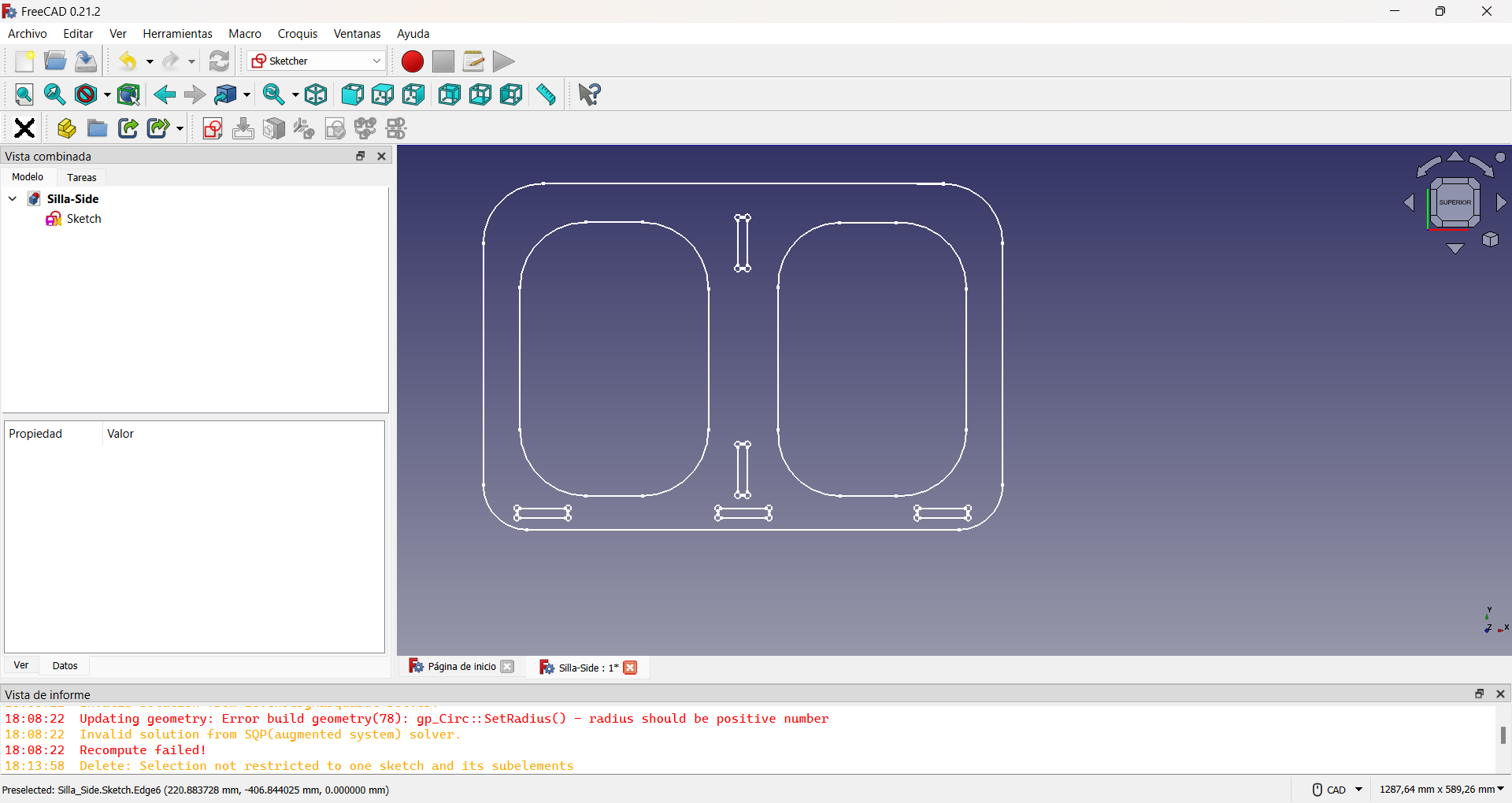
The most complicated design of the three is the side parts of the chair. In the same way I started with a Sketch in FreecAD, in which I drew a rectangle with the lateral dimensions of the chair: 600x400 mm.
Then I decided to round the edges of this part, as it would be the one in direct contact with my son and thus avoid possible accidents. To do so, I drew four 90° arcs of circumferences, one at each corner and converted the initial rectangle to construction geometry. The construction geometry is a resource that, within the Sketcher Workbench, allows to make auxiliary constructions that allow to better define the objects to be built, but that do not appear in the final view of the object to be designed. Finally I traced segments joining each arc of circumference. This can be seen in the following images.
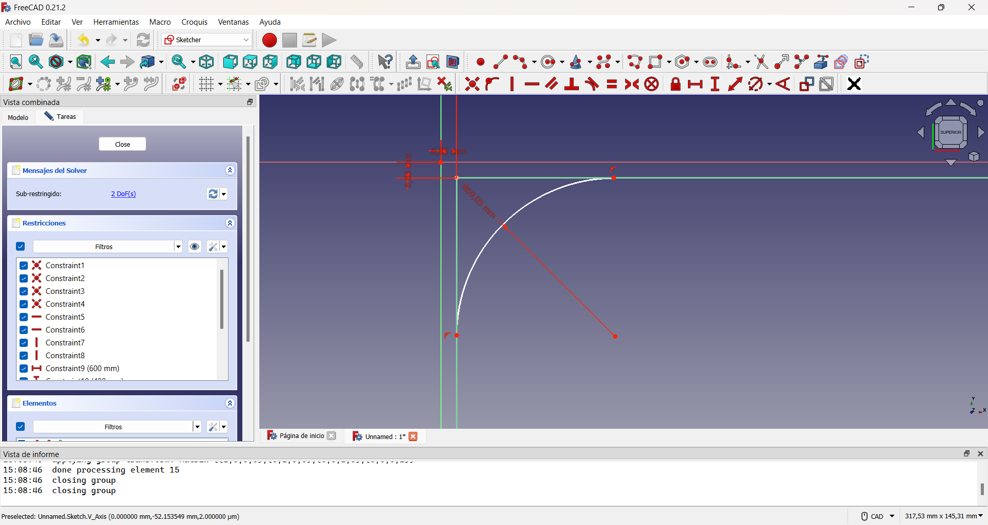
Creating the first rounded edge using a circle arc.
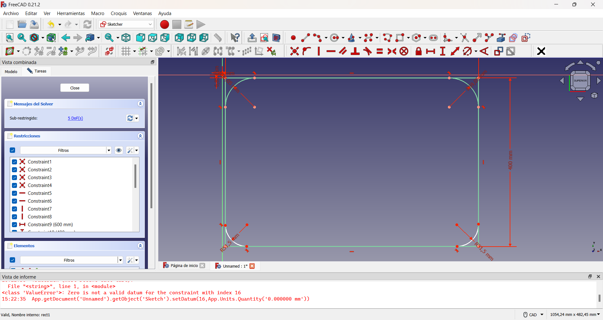
Showing the rounded edges.
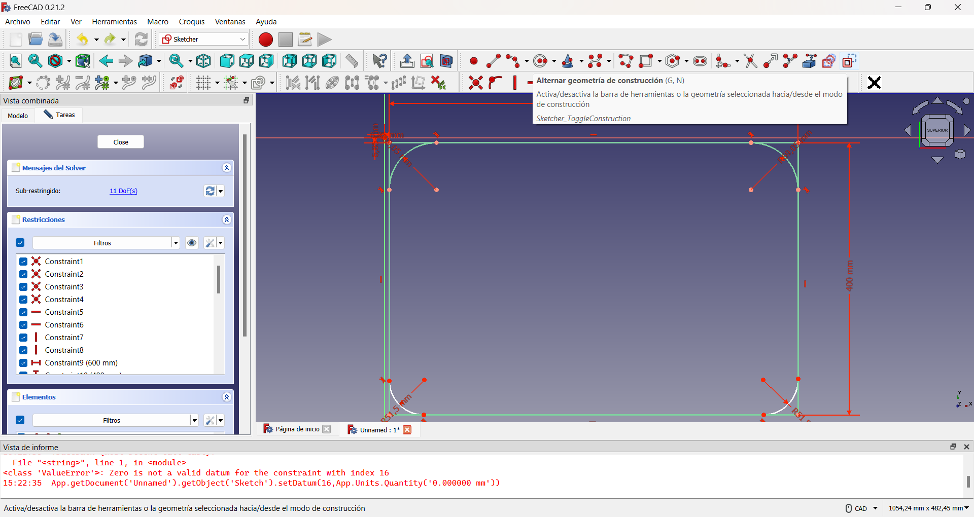
Using the alternative geometry to perform the auxiliary construction of a guiding rectangle.
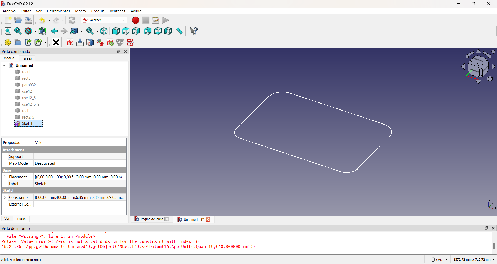
Base of the lateral sides.
Then I made two interior holes to lighten the weight of the chair, imitating the previous procedure, as shown in the figure.
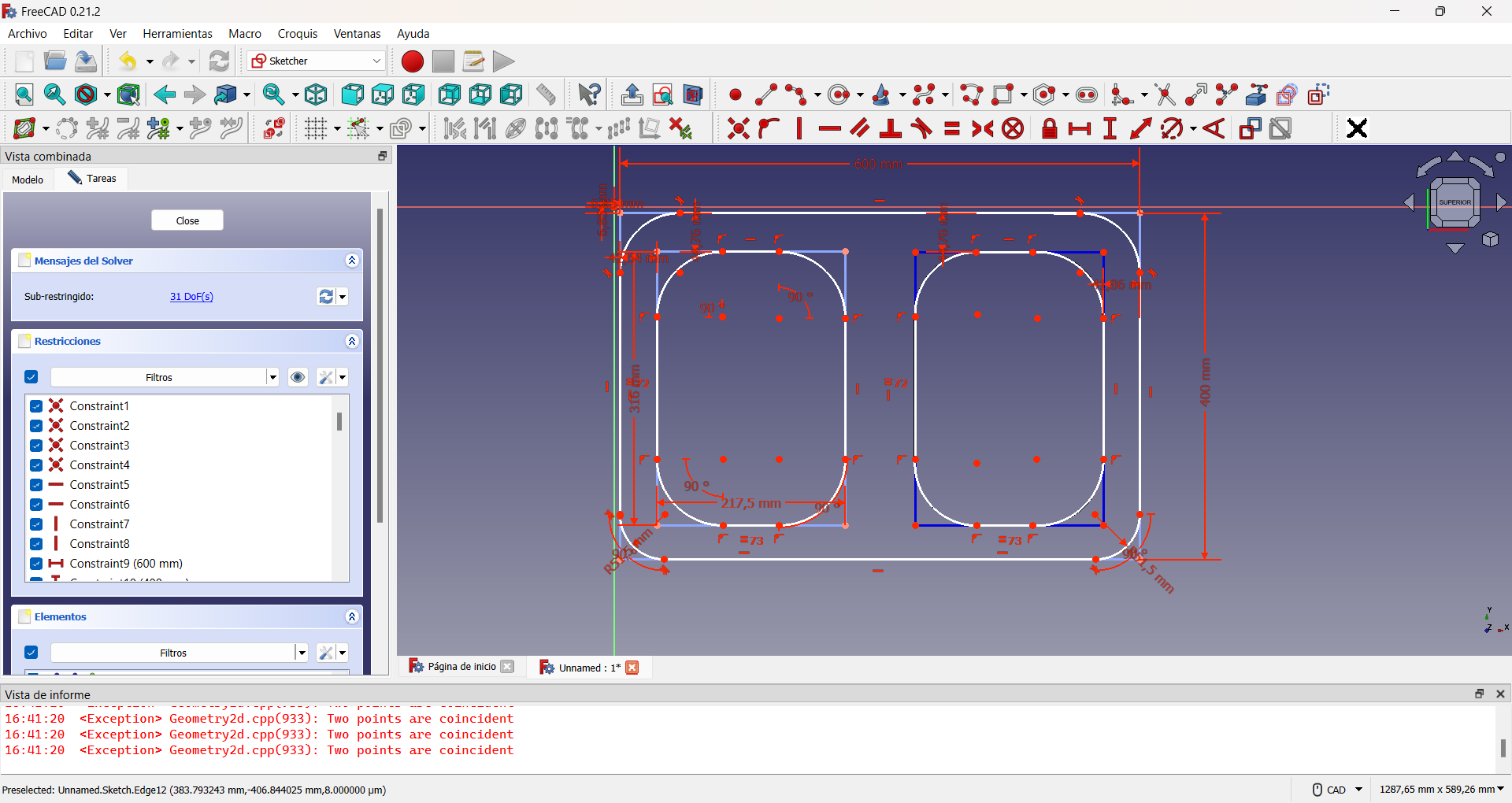
For the assembly holes I had to take into account the previous designs so that they would fit correctly.
To avoid assembly problems it is common to add extra holes to the slots. A common way to do this is the so-called dogbone slot, as I used in my design, applying the same procedure as for the lightening holes. This can be seen in the following pictures.
Creating the circle arcs for dogbone slots.
Using the alternative geometry to perform the auxiliary construction of a guiding rectangle.
Showing the dogbones slots created.
The final result, which can be seen in the following figure, was also exported to .svg format.
The three designs can be seen here.

|

|

|
In the following button you can download all the design files.
Our Fab Lab has one KINETIC-NC and two Shaper CNC machines. Due to the high demand for the KINETIC-NC from other students and the supposed simplicity of my initial design, I decided to use the Shaper CNC machines for the entire milling process. This decision allowed me to work more efficiently and agilely, while also giving me the opportunity to become more familiar with the machine's operation and capabilities.
For the project, I used 12-millimeter-thick plywood with a matte black finish. If you choose a different thickness, you will need to widen the grooves in the side design to ensure a proper fit. This is crucial to ensure the assembly of the final product.
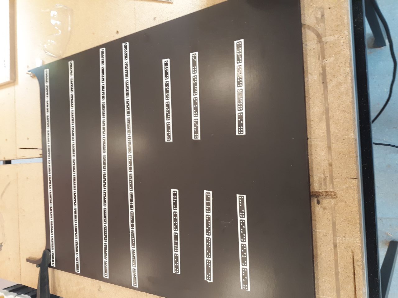
The CNC Shaper operates differently from other machines, as it requires manual spatial positioning. There are three methods for achieving this: utilizing the Workstation Shaper, employing the universal template known as Plate Shaper, or using the Shaper Tape. In all cases, a pattern of white dots on black rectangles with rounded corners and equispacing is present, which enables the front camera of the CNC to locate itself.
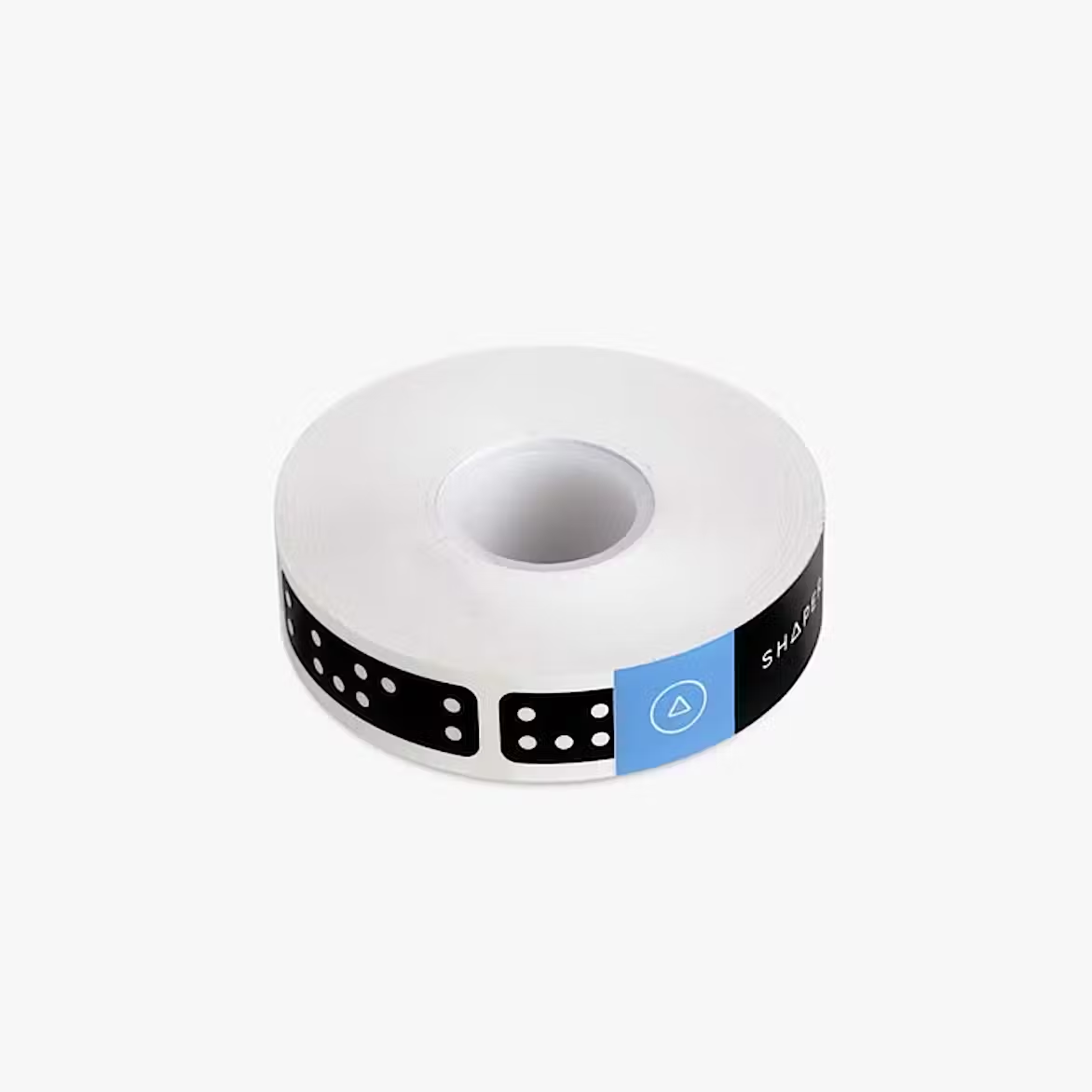
Tape Shaper |
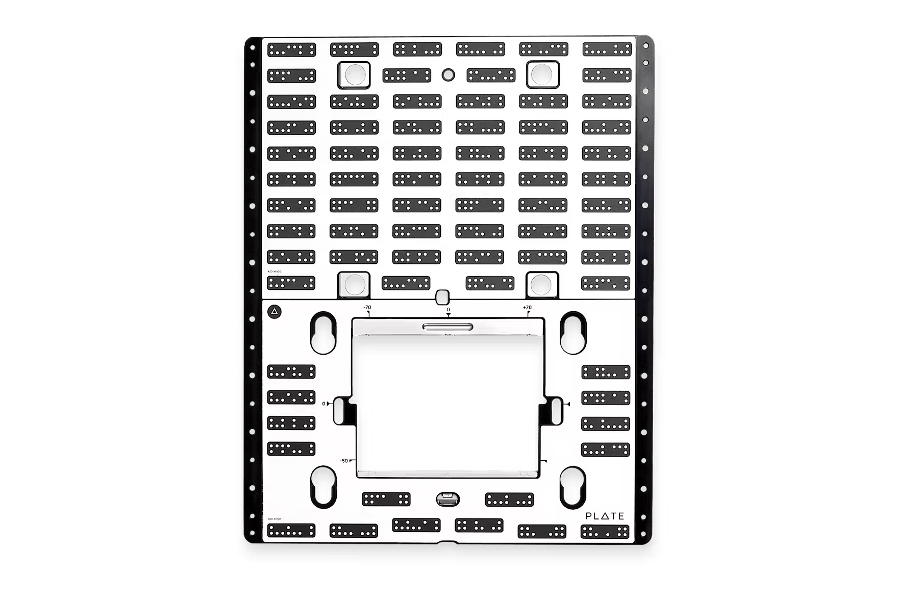
Plate Shaper |
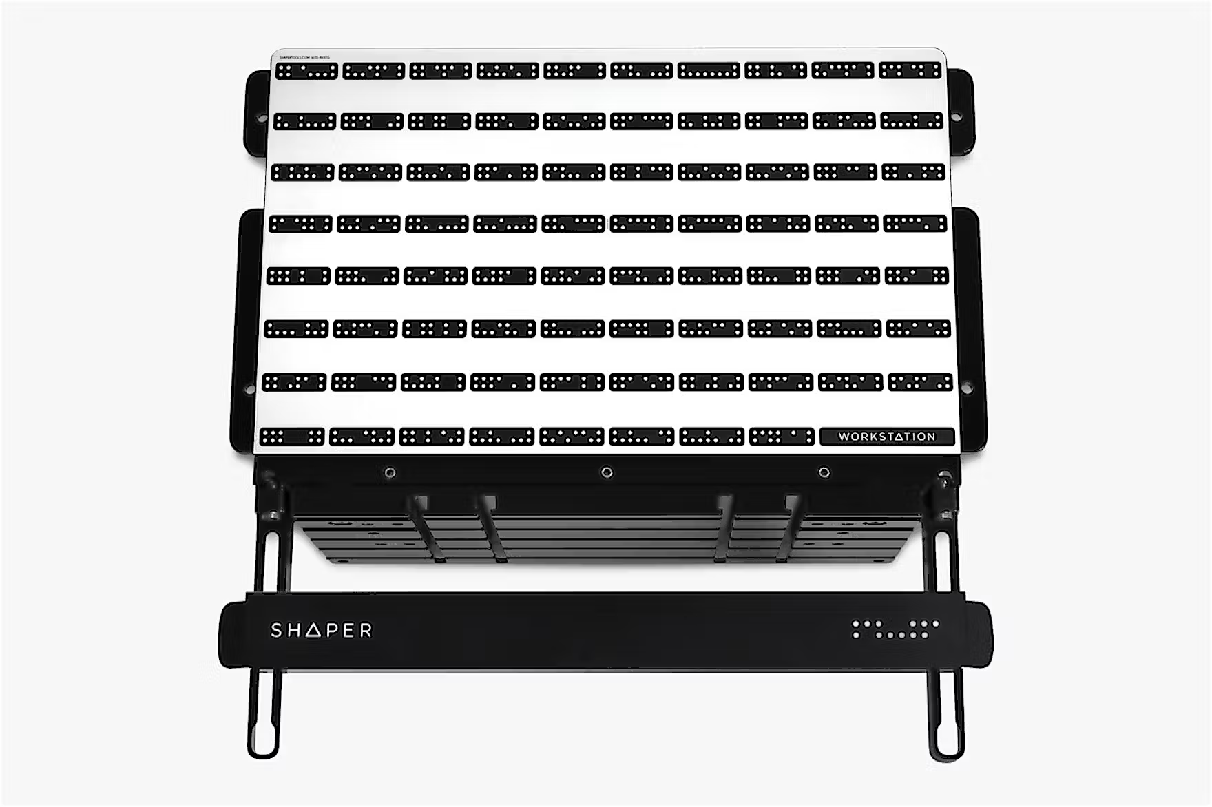
Workstation Shaper |
Images taken for Shaper official web site
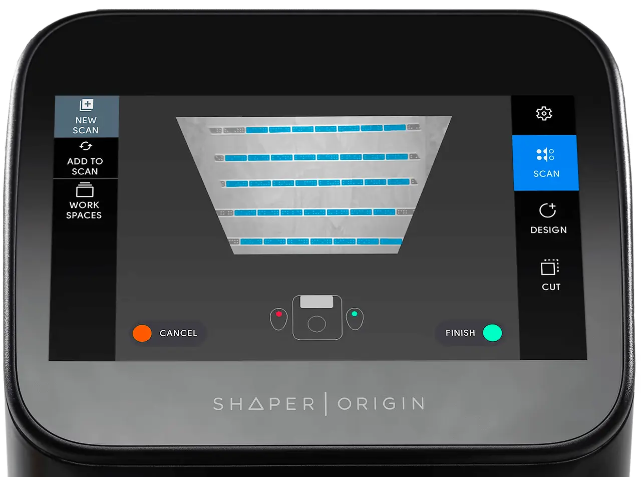
In the Fab Lab, we use only Shaper tape. To use it correctly, always place it parallel to the front camera's field of view and space it between 10 cm and 15 cm apart. Then, scan the entire work area, ensuring that all sections of the Shaper tape are scanned. When cutting the tape, be careful not to cut too close to the black rectangle or through it, as the machine will not scan that part.
It is possible to modify the scanning process by adding new portions of tape or using slots from previous jobs. This model allows for the storage of several hundred workspaces.
|
|
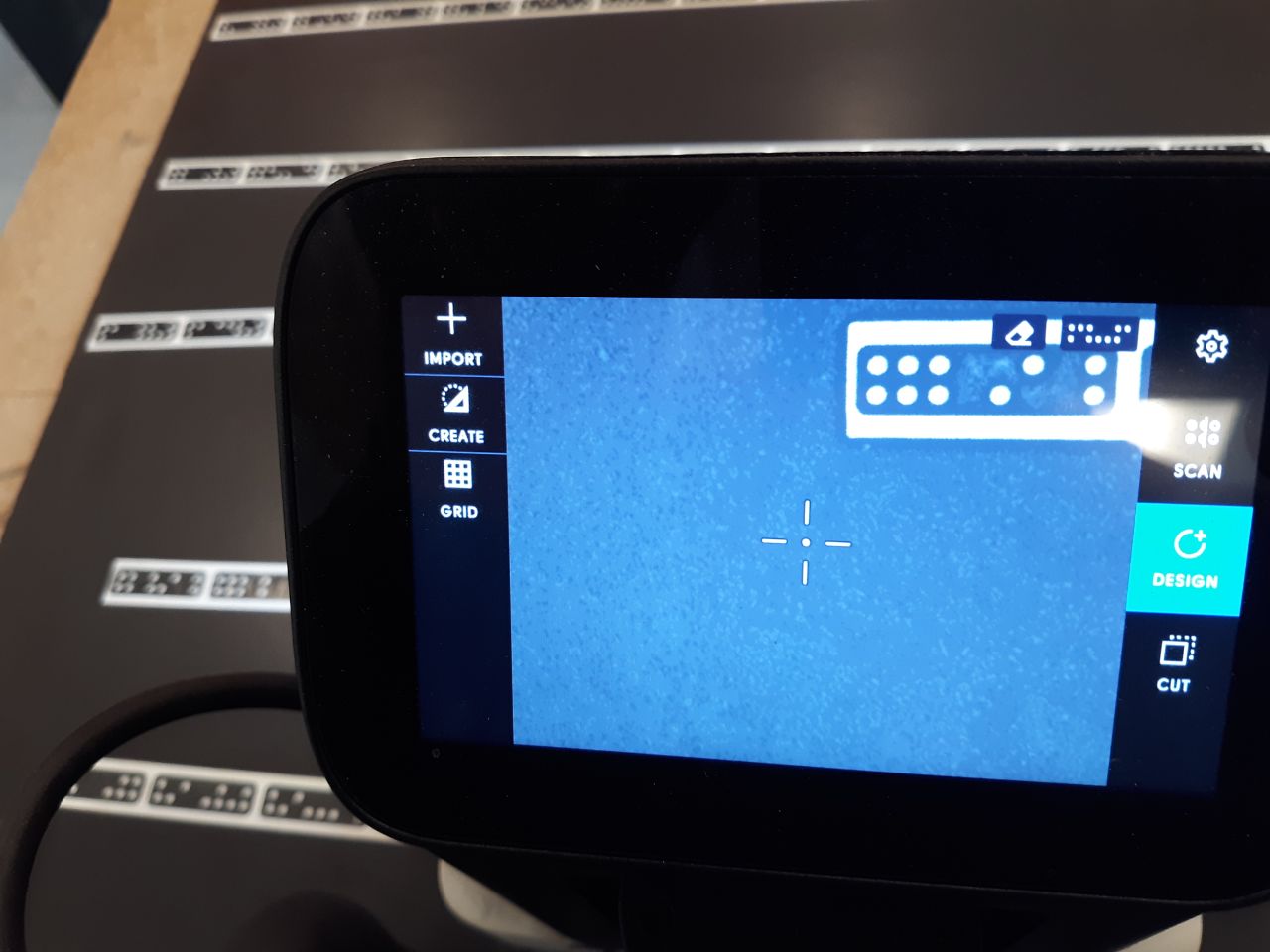
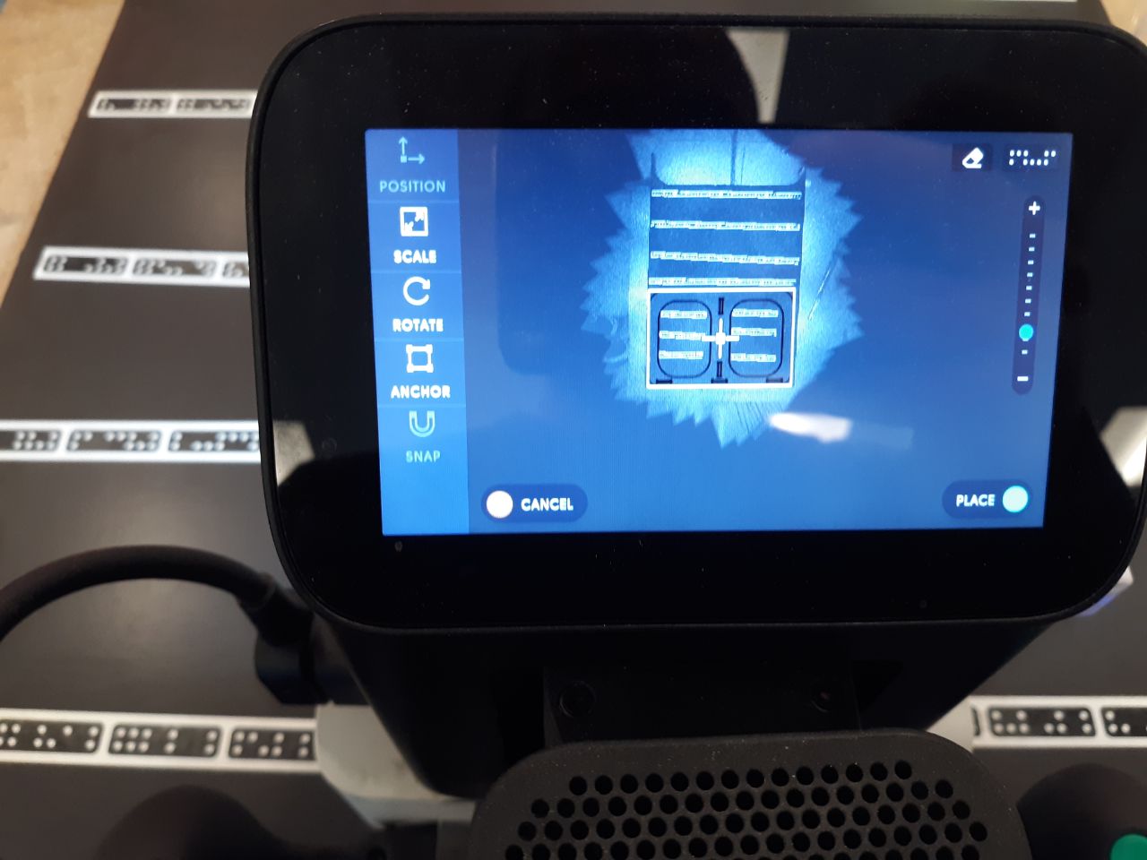
The desired design is created in the workspace, either on the CNC or by importing a previously designed one. In this case, both methods were used: the three designs shown above were loaded and a text was included on the back of the chair, which will be referred to later.
|
|
Selecting the appropriate router bit is a crucial aspect of the process. If you lack experience, conducting prior research can ensure the efficiency of the process. Router bits are available for milling wood exclusively or for various materials. Additionally, choosing the correct diameter of the router bit enables you to fill tight spaces while routing. Each diameter has a maximum milling depth. In this case, 6 mm router bits were chosen because smaller diameters have a maximum depth of less than 12 mm, which is the thickness of the wood used.
Placement of a wood router bit. |
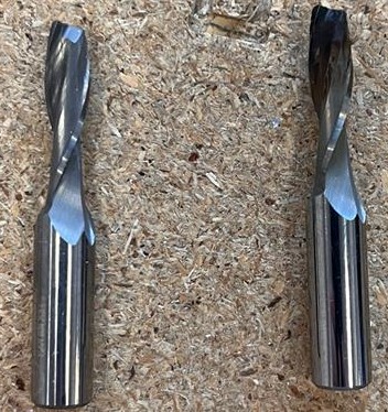
Router bit for variety materials. |
Router bit for engrave. |
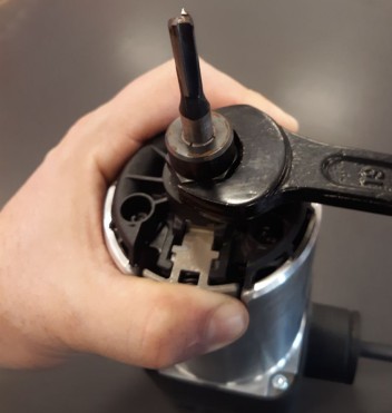
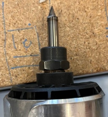
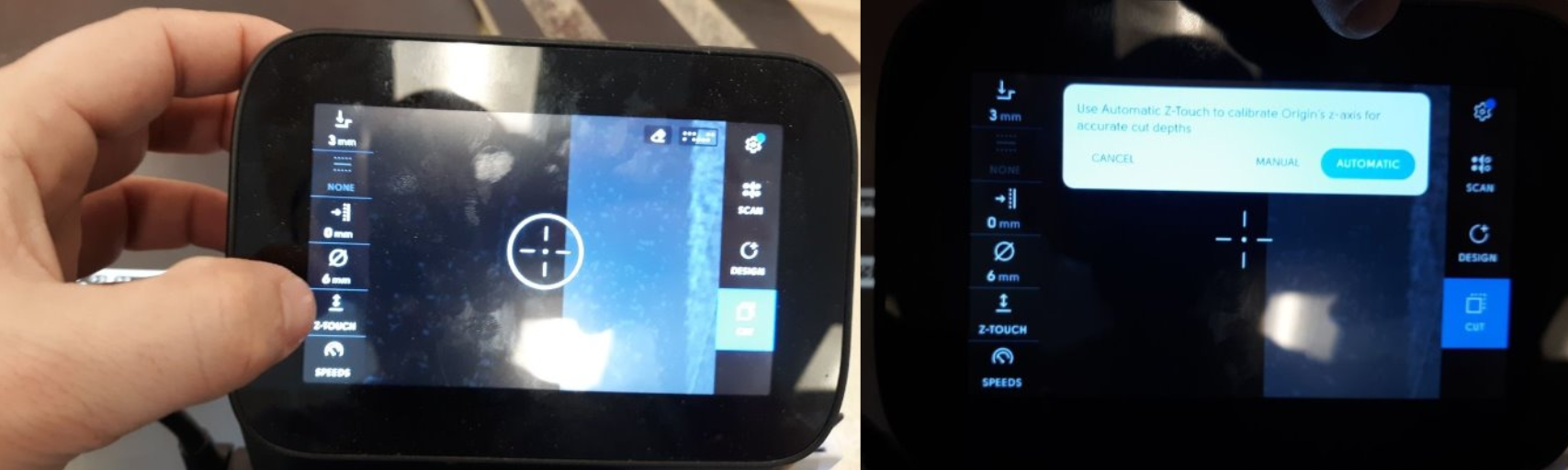
It is important to note that calibration must be performed in the vertical z-axis every time the router bit is changed, as well as at the start of each job. Please refer to the accompanying image for the calibration process.
Next, the milling parameters must be selected. Begin by setting the dimensions of the router bit to be used.
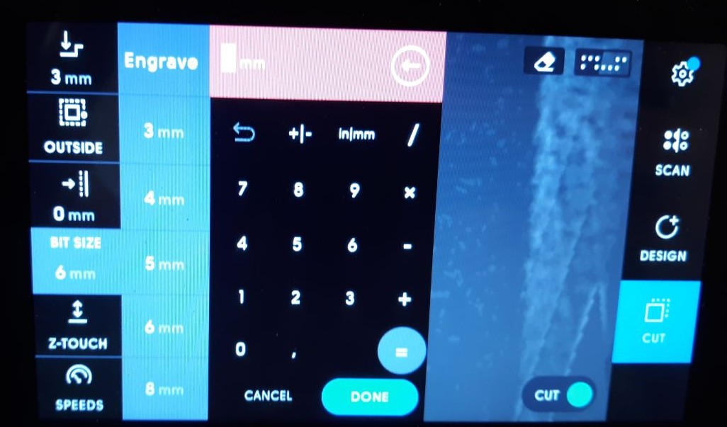
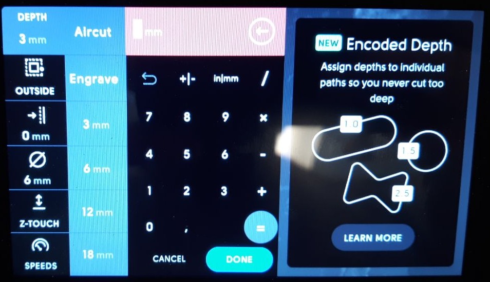
After choosing the appropriate router bit, it is crucial to establish the depth of each pass. To accomplish this, follow this rule of thumb: if the diameter of the router bit is greater than 3 mm, the depth should be no more than half of that diameter. Conversely, if the diameter is less than 3 mm, the depth should not exceed 10% of the bit diameter. It is essential to adhere to these guidelines to guarantee precise and safe work on your drilling projects.
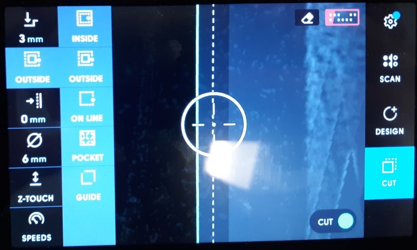
When choosing the location of the router bit in relation to the lines drawn on the drawing, it is important to follow certain defined patterns. For interior areas, it is recommended to use the 'inside' option, while for exterior areas, the 'outside' option should be chosen. When considering the complete removal of an area, it is important to note that the 'pocket' function should only be used if the cut's total depth is less than the material's depth. In this case, it is more efficient to use the 'inside' option for the cut. Following these guidelines will ensure accurate and efficient work on your machining projects.
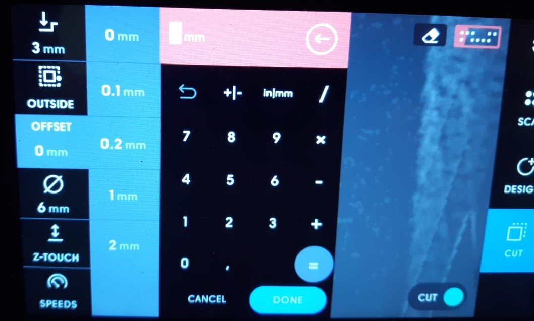
Offset is a crucial tool for correcting designs, particularly when precise adjustments are necessary to fit with other parts. It can be positive, negative, or zero, allowing for fine-tuning of designs and ensuring accuracy in part manufacturing. The ability to adjust the offset according to specific needs is critical in the design and production process.
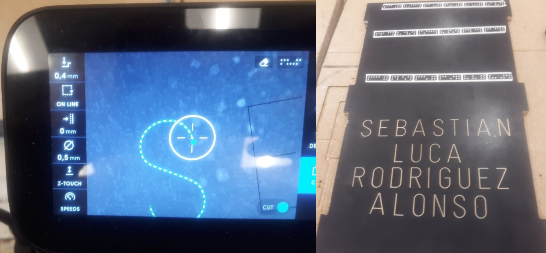
Once the parameters have been set, the milling process can begin. It is important to ensure that the machine is placed on the mapped surface in such a way that the front camera can always see enough points to determine its location. This can be easily determined by checking the indicator in the upper right corner of the screen, as shown in the picture below.Once the parameters have been set, the milling process can begin. It is important to ensure that the machine is placed on the mapped surface in such a way that the front camera can always see enough points to determine its location. This can be easily determined by checking the indicator in the upper right corner of the screen, as shown in the picture below.
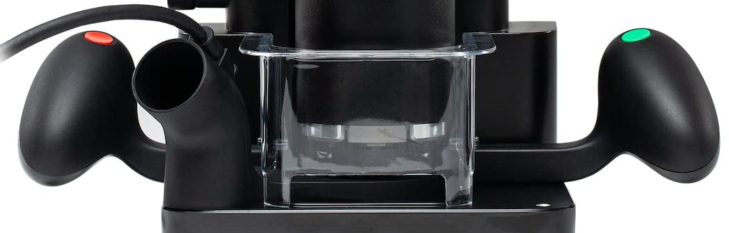
To begin milling, press the green button located on the right side of the machine. Once pressed, the machine will descend to the preset depth, enabling you to start milling by following the dashed lines. If you press the green button again, the machine will automatically move in a circular motion on the screen, and you will only need to follow it, similar to a video game. Press the green button twice at the start of milling to enable automatic tracking of the dashed lines without the need for constant button pressing. To stop the milling operation, use the red button located on the left side of the machine. The operation will also stop automatically if the milling machine moves too quickly.
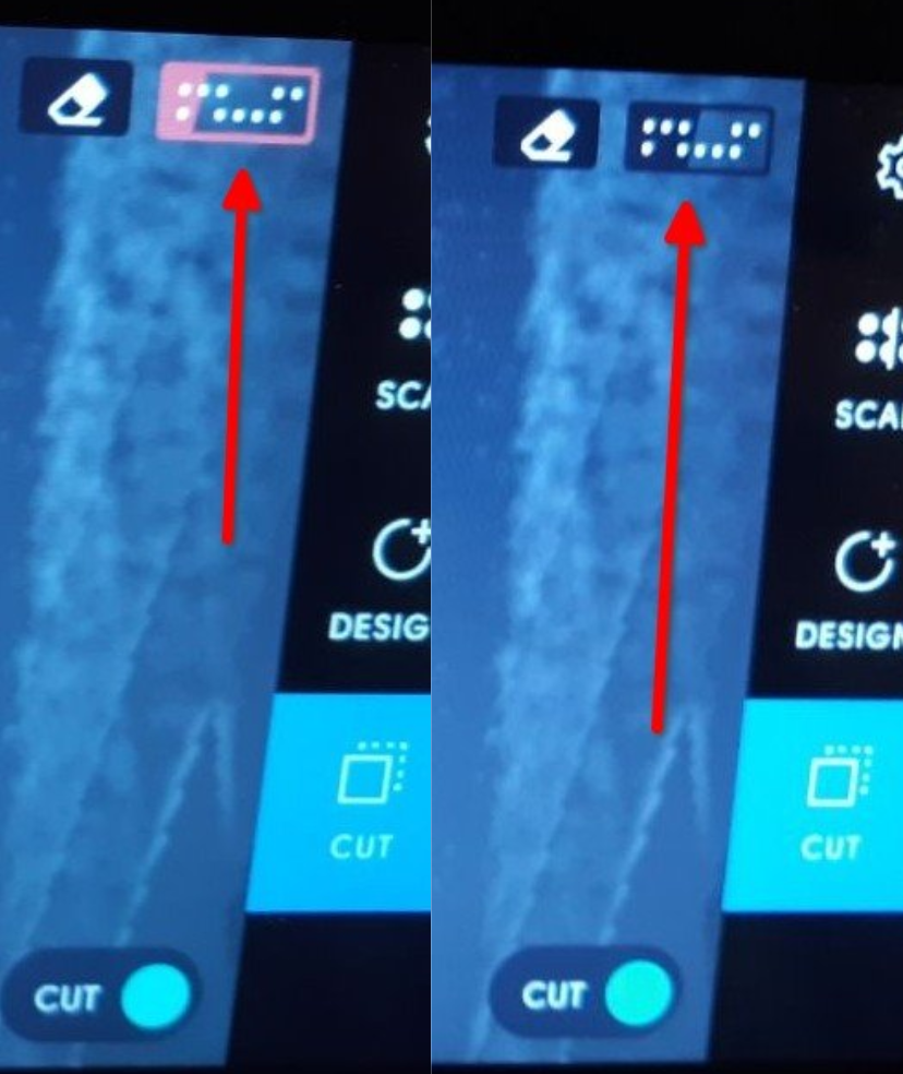
To engrave the painted surface of the wood, select the 'engrave' option for tracing depth and choose 0.4 mm. This method was used to place my son's name on the back of his chair.
The assembled final product, without the use of fasteners or glue, is visible below.
Making something with a bigger machine
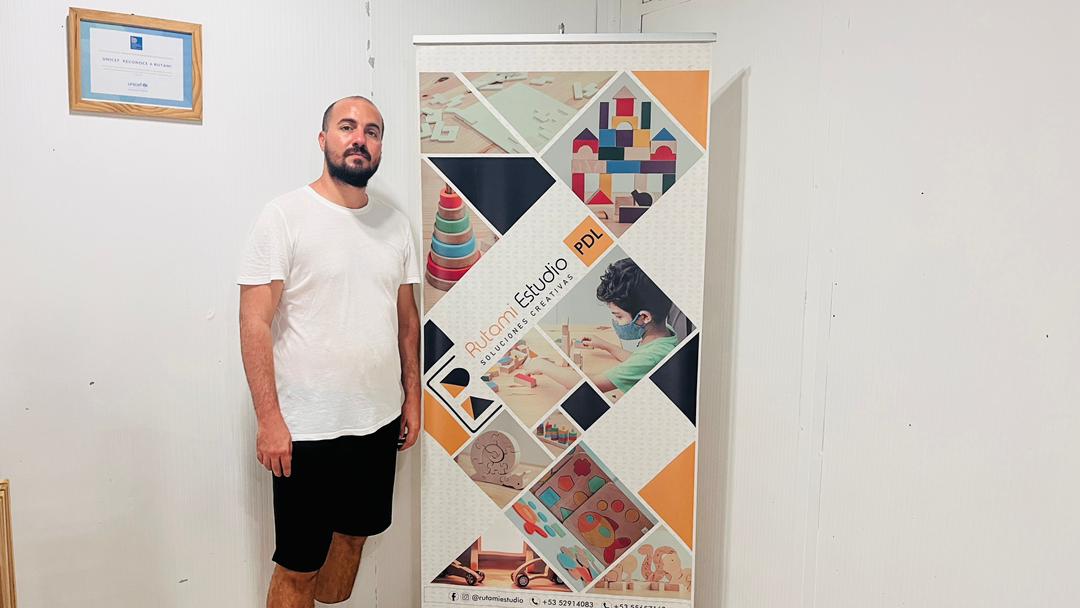
After a recommendation from Niels I set myself the task of making something on a larger CNC. For this I went to the facilities of the Rutami Estudios PDL (Local Development Project, PDL by its acronym in Spanish), located in the capital municipality of Plaza de la Revolución in Havana, Cuba: yes, this part of the individual assignment was done in conditions of high tropicallity. Rutami Estudios PDL is a workshop of desing and manufacture of didactic wooden toys for girls and boys and others structures of wood. They graciously offered to provide their CNC machine for the completion of this assignment.
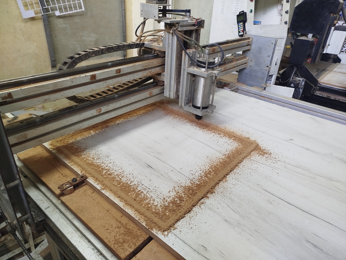
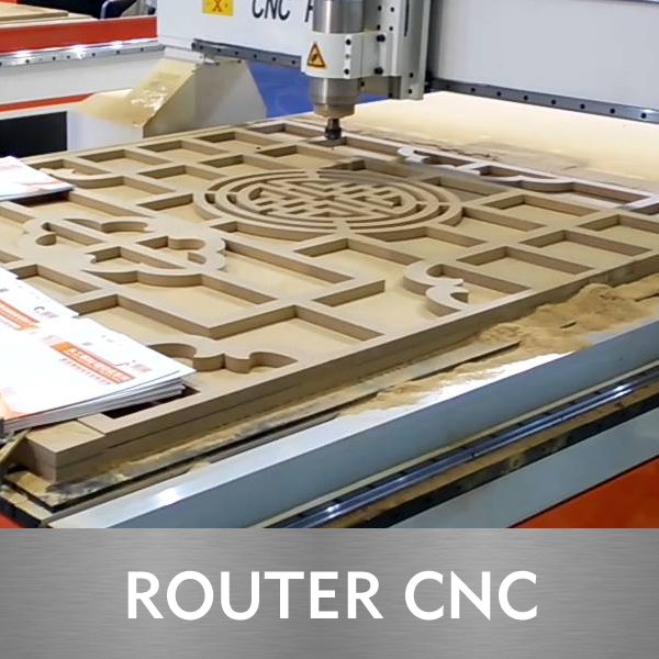
The CNC machine that Rutami Estudios PDL owns was designed and assembled from different CNC parts that were purchased, not being all fully compatible and having to make mechanical and electronic modifications to achieve compatibility of the entire system. The CNC bed has a size of 2440x1220 mm and the spindle has a range of movement of 200 mm, being possible to work pieces of a maximum volume of approximately 0.6 m3. The spindle motor has a power of 1 KW and the spindle speed range is between 5000 and 24000 revolutions per minute (RPM), although they typically work between 8000 and 12000 RPM. The spindle cooling system is water-cooled. The maximum speed of movement in the horizontal plane of the head is 1200 mm/min, although the adjustment of this speed must be made according to the material to be used for milling. The whole system works with three-phase current. Servomotors with helical couplings and a chain transmission system are used to move the spindle. This image shows a view during a cutting process.
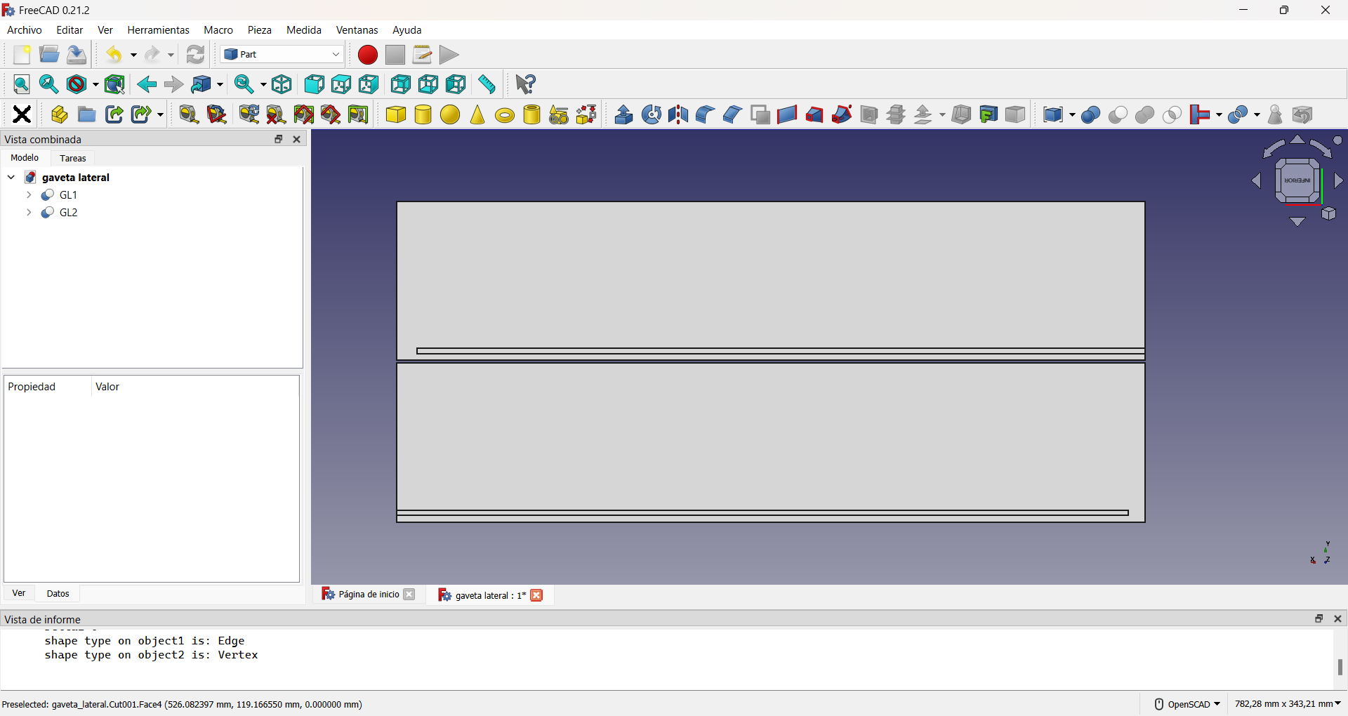
To make use of this CNC machine I made a design of a drawer to be used as a storage box. I started, as in previous weeks, with a Sketch in FreeCAD and by extruding the drawings and other boolean operations I made the parts that compose the drawer: front, sides (both equal), bottom and floor. The figure shows the result for the sides.
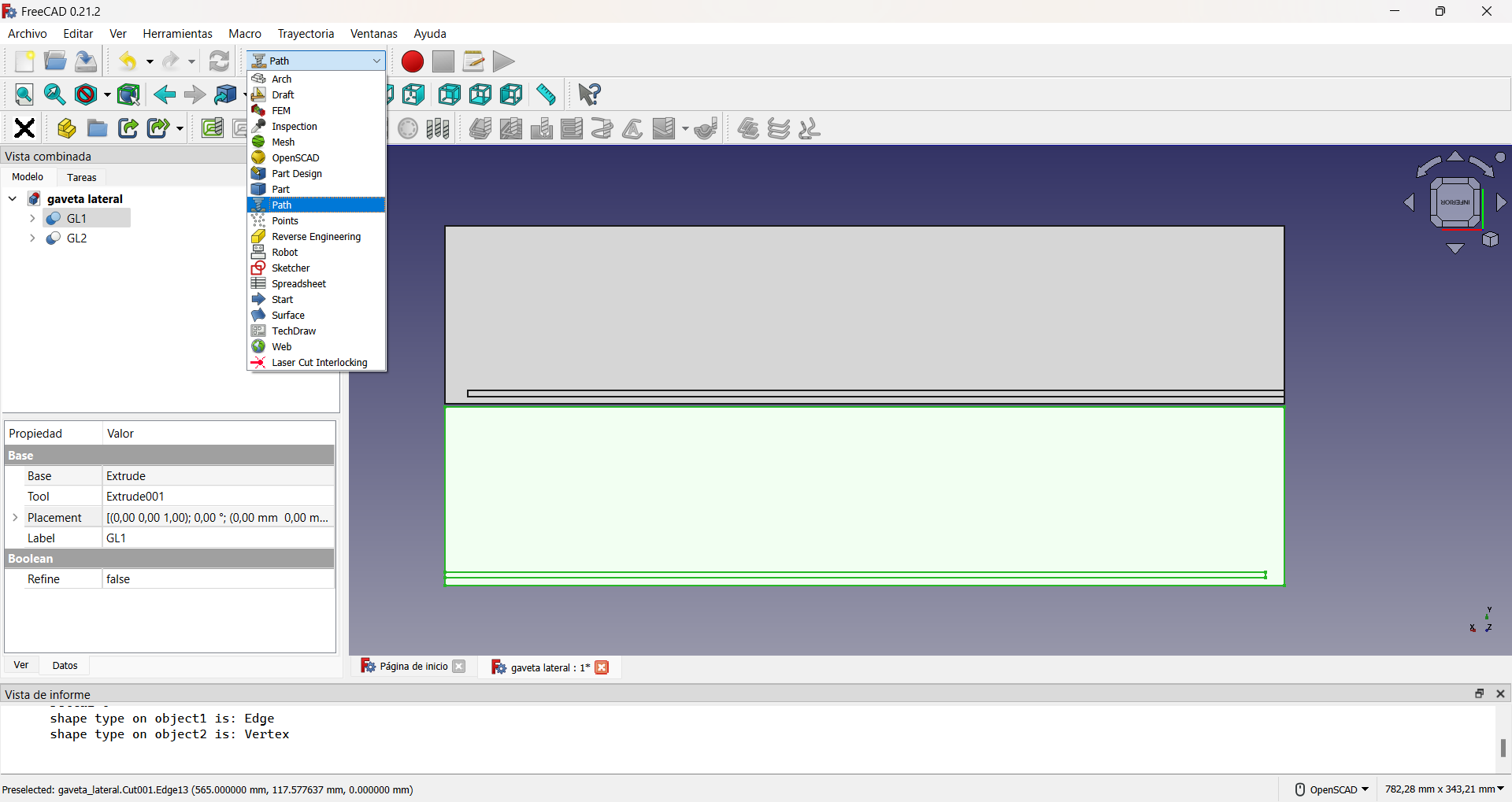
Open the FreeCAD Workbench Path.
In FreeCAD's Workbench Path the first step to be performed is to create a path job.
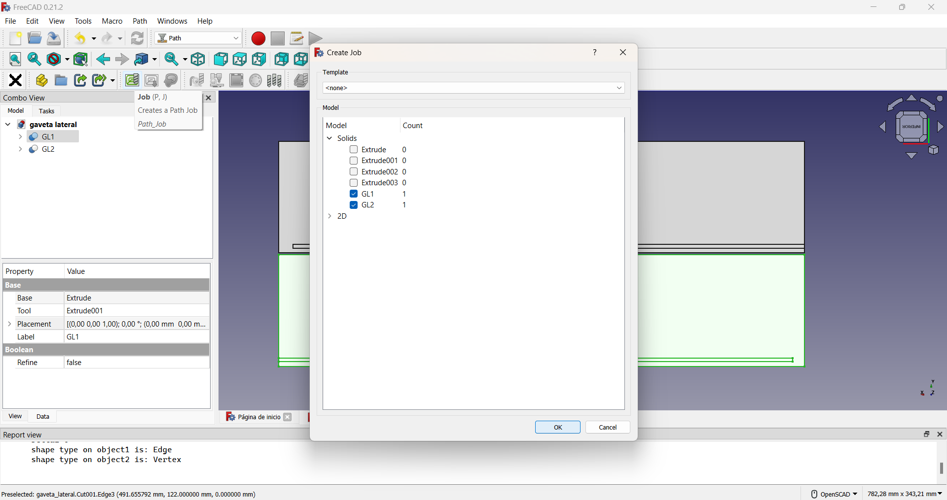
FreeCAD automatically creates a work volumen with a clearance of 1 mm on each side in all three axes, in the Job Edit window. It is convenient to increase these distances in the x and y axes to 5 mm and to set the distances in the z axis to zero 0 to avoid overdimensioning the material. This is shown in the following video.
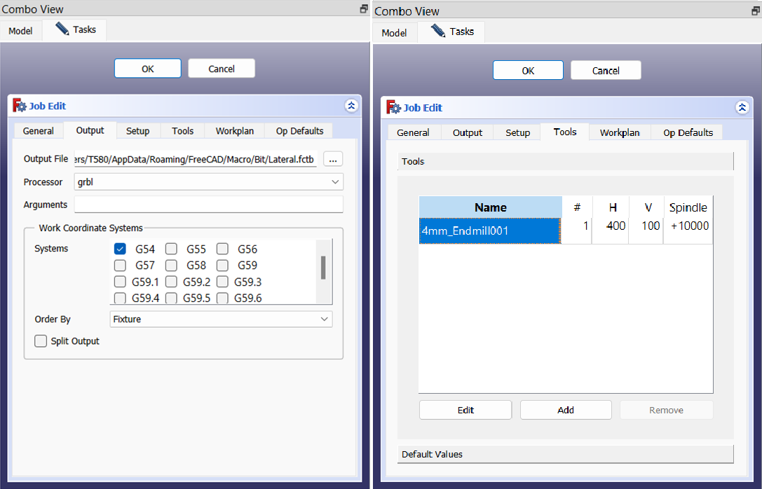
In the Job Edit window, the characteristics of the tool(s) to be used are configured. These are: milling cutter speed in the horizontal plane (\(H = 400\, \text{mm/s} = 24000\, \text{mm/min}\) for our piece), milling cutter speed in the vertical direction (\(V = 100\, \text{mm/s} = 6000\, \text{mm/min}\) in our case) and the speed and direction of rotation of the milling cutter (\(\text{Spindle} = +10000\, \text{RPM}\) in our case). For our process we use a 4 mm diameter Endmill. The choice of the working coordinate system used for programming the CNC is also selected in this window. The most usual is to use the G54 system, which corresponds to select work coordinate system no. 1, which is the most usual for milling flat sheets of wood or materials with similar characteristics. In our case the material to be worked is MDF or Medium Density Fiberboard, which is composed of wood fibers and synthetic resins, and offers a smooth and uniform surface ideal for furniture such as our drawer.
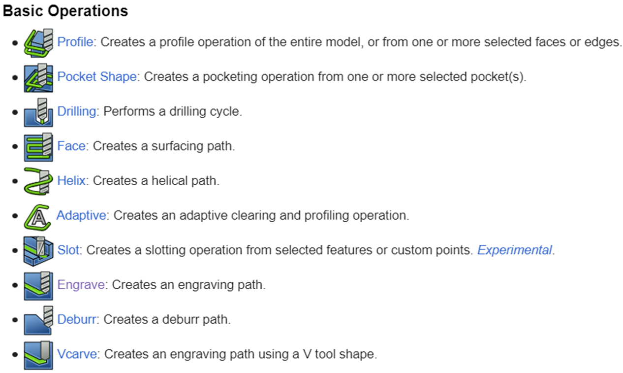
Image taken for CAM Workbench page of FreeCAD.
The FreeCAD CAM or Path Workbench has a number of basic operations that allow the milling of parts where the level of complexity is not high. These are the ones we used for our drawer, as the geometry of each part was simple. In this case we used the basic operations Profile and Pocket Shape.
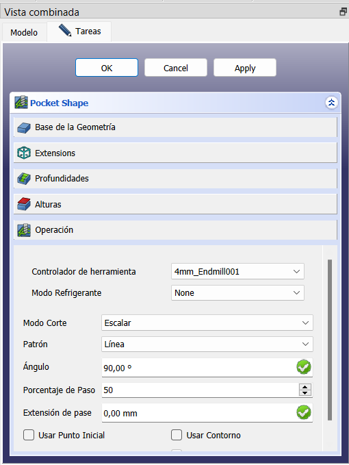
The Pocket Shape configuration was chosen in this case as a Scalar cutting mode, an in-line pattern, a 90° cutter location angle and 50% pitch percentage, due to the characteristics of the part. The other parameters remained the same as they appear by default.
Using the CAM Simulator button, you can simulate a part of the cut or the entire part, depending on your interest. Our main concern at the time of making the cut was that the corners were made continuously, without jumps due to the mechanics of the CNC, so we performed the simulation of this process. This is shown in the following video, where in the upper right corner appears the CAM Simulator button icon.
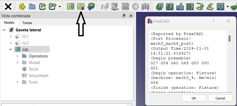
Selecting the job and pressing the post-processing button (indicated by the arrow in the figure) generates the gcode needed to control the CNC machine.
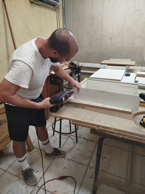
To mill the sides and front of the drawer, we place the MDF sheet on the CNC bed and start the process. This CNC has the characteristic of being completely open and built in a semi-professional way, so Rutami Estudios PDL team members have established a series of safety measures to avoid accidents. The first rule is to perform small jobs in each milling process. For this reason we decided to divide the cuts into two parts, the sides and the front in that order. The second rule is to always clean the work area after a milling process. This allows us to detect errors in the operation of the machine and to prevent the occurrence of fires due to excess wood chips. Finally, and most importantly, never leave the room where the CNC is turned on and, in case of emergency, press the stop button. The following video shows these two processes.
As I said before, this part was carried out in highly tropical conditions, which meant that I did not have at my disposal the amount of material that I would have liked. That is why the lower and rear parts of the drawer were made with materials recovered from previous projects that Rutami Estudios PDL had done and that were cut. This gave me the task of making my entire drawer design based on this premise. For the floor of the drawer I used a 4 mm thick MDF board and for the bottom I used a 12 mm thick MDF board. In addition, unlike the way the planks are attached at Fab Lab ULB, Rutami Estudios PDL holds them by means of special anchors placed on the bed, which allows a better use of the entire area of the plank. The results of the cutting can be seen in the image on the left next to the supports used to fix the plate.
The source files of the design can be downloaded by clicking on the following button.
To complete the assembly of the drawer, I used wood logs and polyvinyl acetate glue.
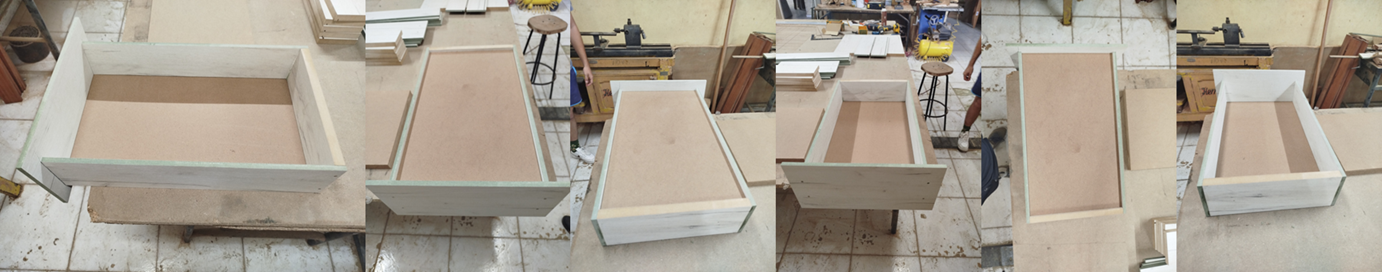
The following image shows the assembled drawer from different angles.