2. Computer Aided design
Computer-aided design (CAD) is a crucial tool in the conception and development of projects in various disciplines, including architecture, engineering, and industrial design. Specialized software enables professionals to create, modify, analyze, and optimize designs, resulting in virtual models of their products or projects in two or three dimensions. This ability to generate virtual representations facilitates visualization, collaboration, and early detection of possible errors, contributing to the reduction of costs and time associated with physical manufacturing or construction. The use of CAD tools has become a standard in the industry, offering professionals the ability to refine their designs and projects efficiently and accurately. As a result, the quality and feasibility of the proposed solutions are improved.
Research
This week, I had two main 3D design ideas. Firstly, I designed a beach for the wave flume using the FreeCAD program. To learn how to use the program, I watched tutorials on Bernardo Tutorials' YouTube channel (https://www.youtube.com/@BernardoTutorials). I made use of the main tools, particularly Part Design and Sketch.
A beach is a type of wave-suppression element that is situated within the extinction zone of a wave flume. Beaches are essential structures designed to regulate and disperse wave energy in aquatic environments, such as wave flumes utilized for the study of wave behavior. They are situated within the extinction zone, which is the region where wave energy gradually dissipates as it propagates inland. The primary function of a beach is to reduce wave height and wave energy, which serves to safeguard structures and equipment situated upstream in the wave flume. Furthermore, beaches can also be employed to simulate natural coastal conditions in laboratory settings.
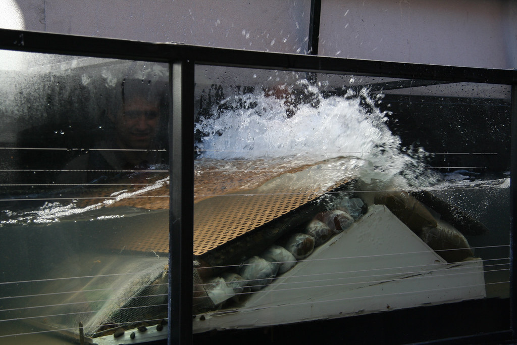
Example of beach. Image taken for the https://www.flickr.com/photos/archivo-escuela/7154072548/in/photostream/.
More design of beaches can be found here
FreeCAD is a powerful open-source parametric 3D CAD modeler that allows users to design real-life objects of any size. Its versatility lies in its ability to create complex and detailed designs for various fields such as mechanical engineering, architecture, and product design. FreeCAD's parametric modeling feature enables users to easily modify designs by changing parameters, making it an ideal tool for iterative design processes and rapid prototyping.
One of the key advantages of FreeCAD is its extensibility through a modular architecture and a wide range of community-developed plugins. This allows users to customize the software to suit their specific needs and integrate it with other tools and workflows, enhancing its flexibility for diverse design requirements.
Additionally, FreeCAD supports a wide range of file formats, including STEP, IGES, STL, and others, enabling seamless collaboration and interoperability with other CAD software and manufacturing processes. Its open nature and active community make it a valuable resource for both hobbyists and professionals seeking a reliable and versatile CAD solution.
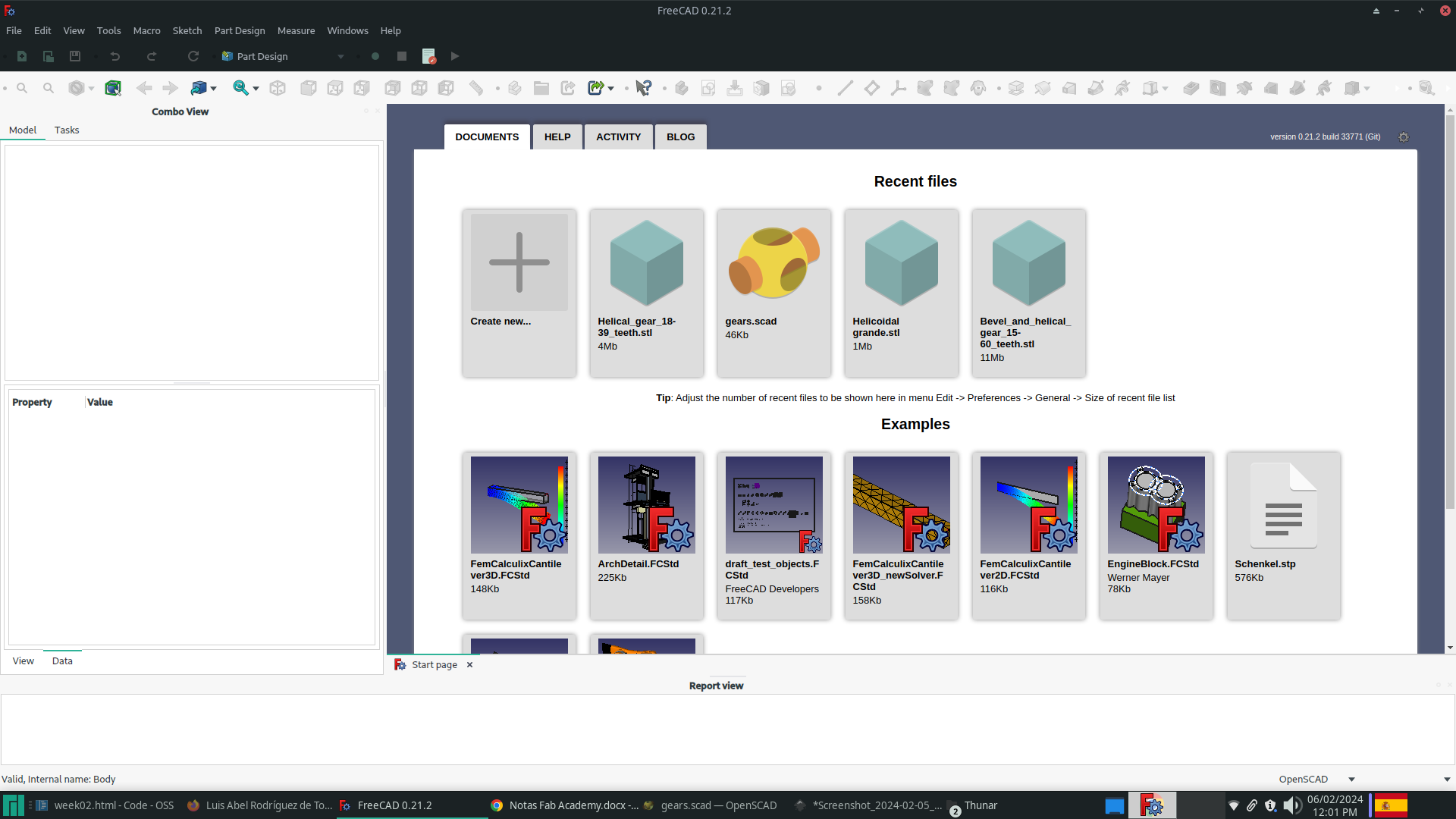
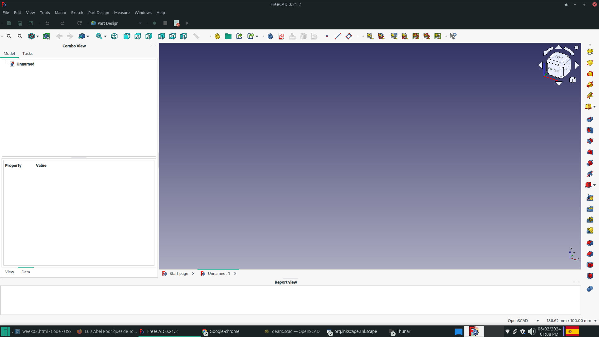
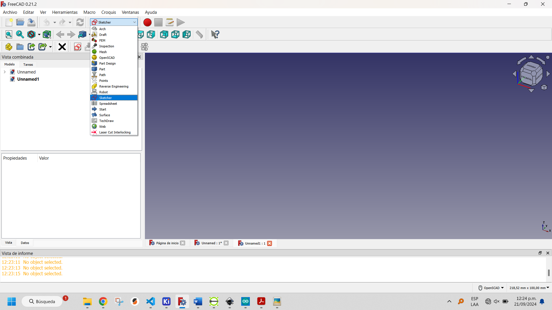
The first step is to select the Part Design option from the Workbenches menu. Then open a new document in the File tab, using the New File button on the File bar or the Create New... button in the workspace.
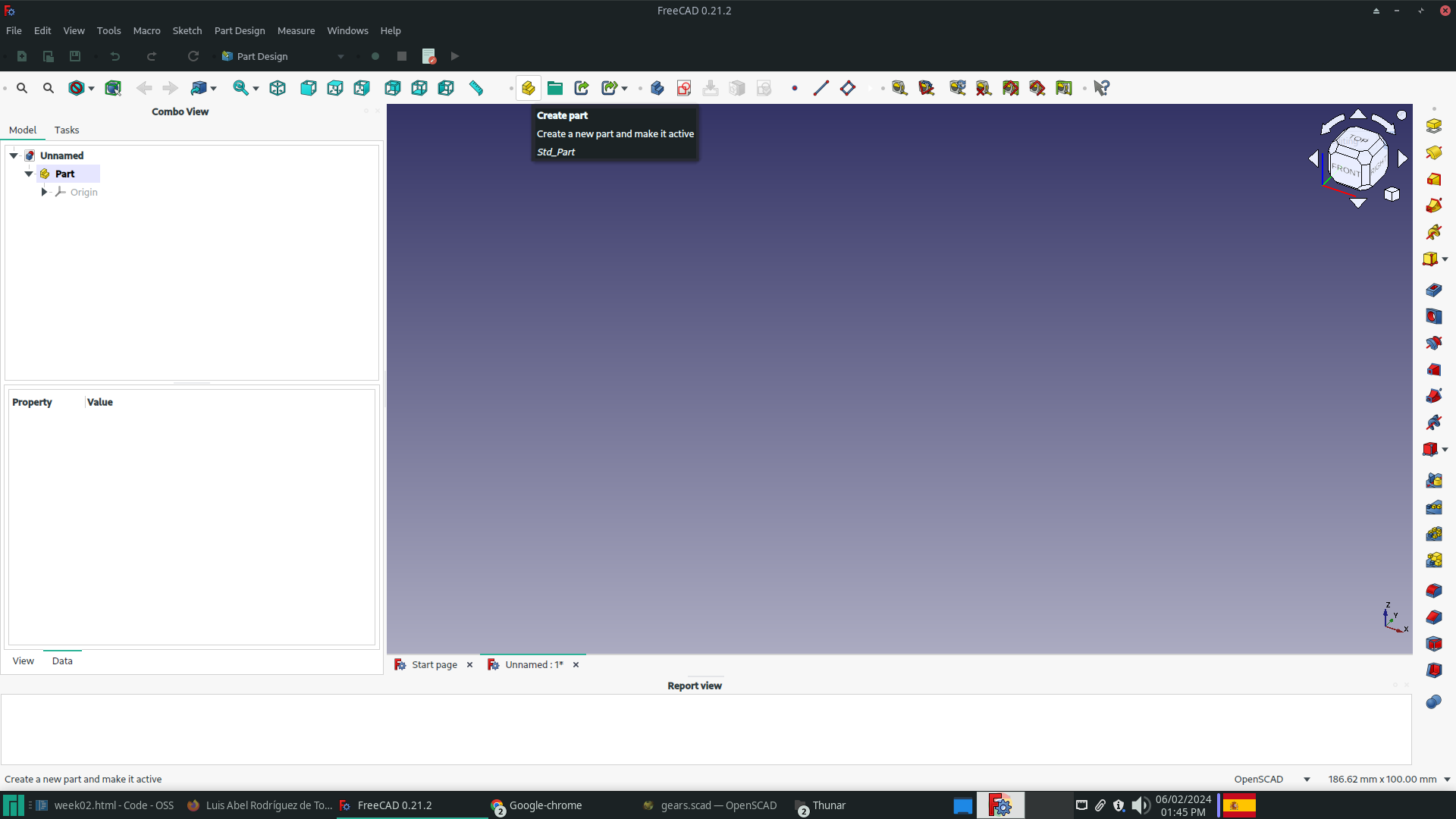
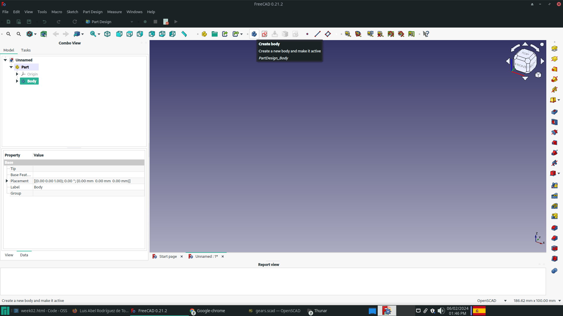
To create a part, first click on the 'Create part' button in the Structure bar. Then, create a body by clicking on the 'Create body' button in the Part Design Helper bar.
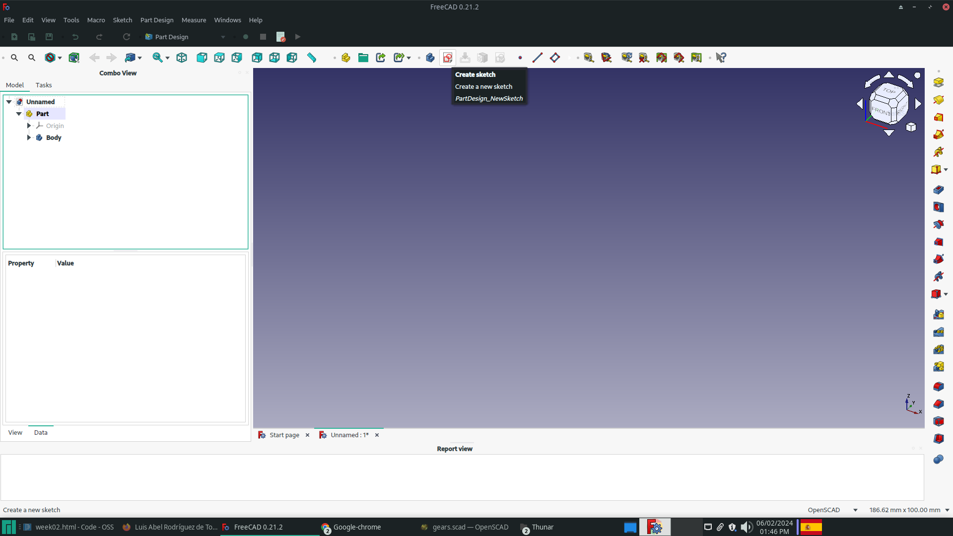
To begin the sketch design, click on the Sketch button located on the Part Design Helper bar. This will establish the necessary structure.
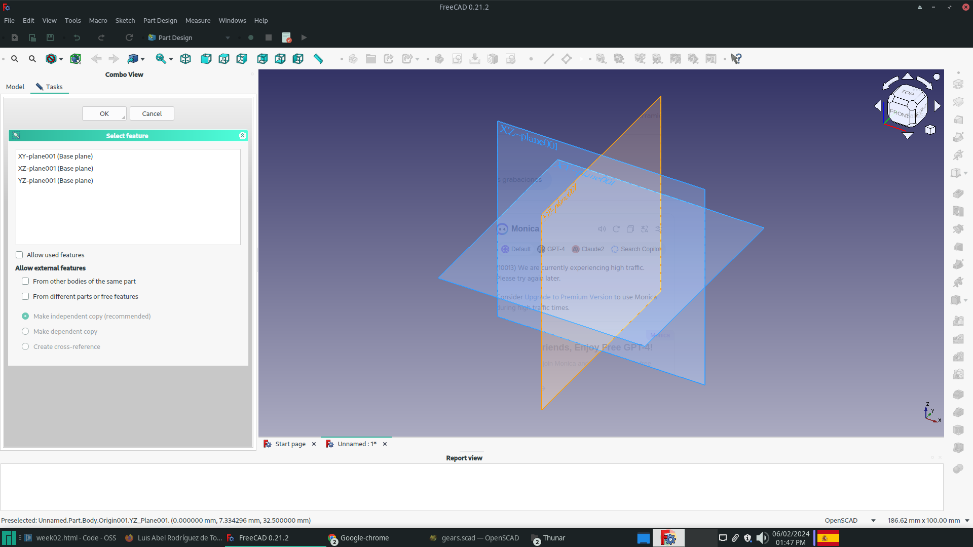
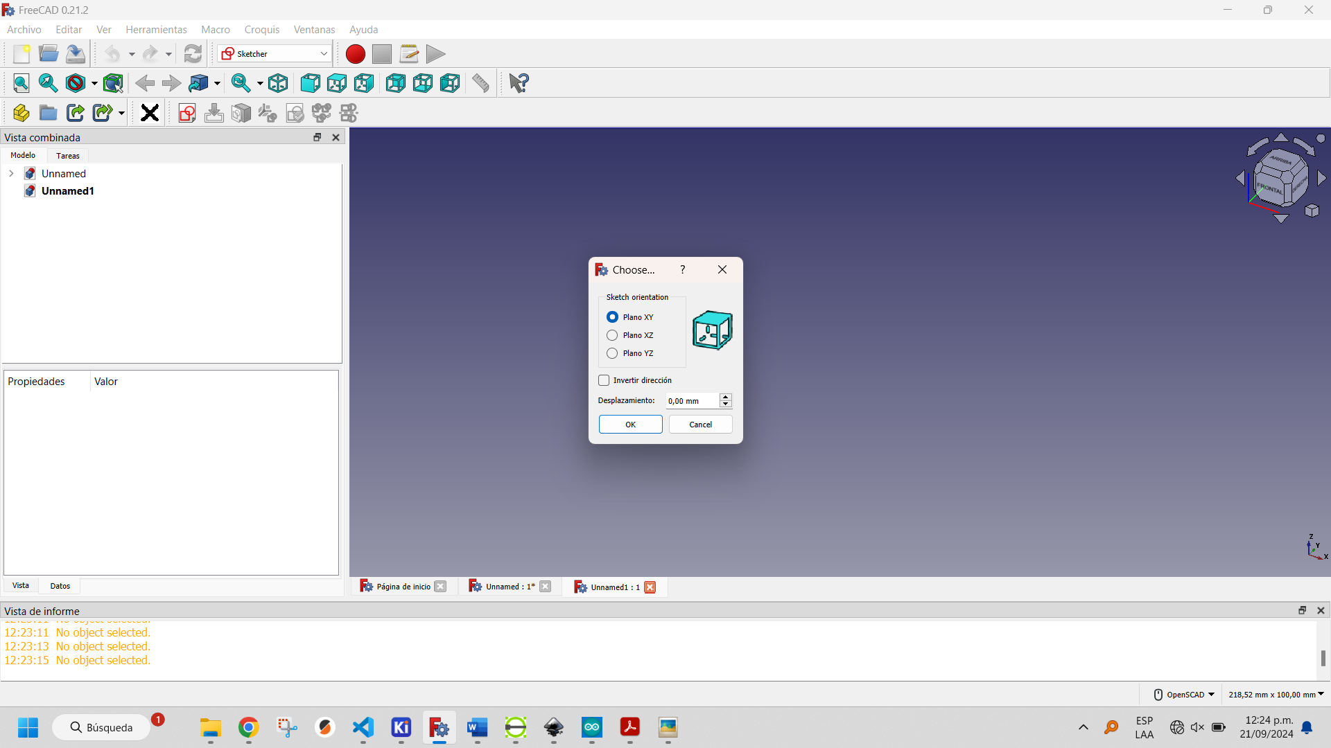
After creating the sketch, select the plane to work on.
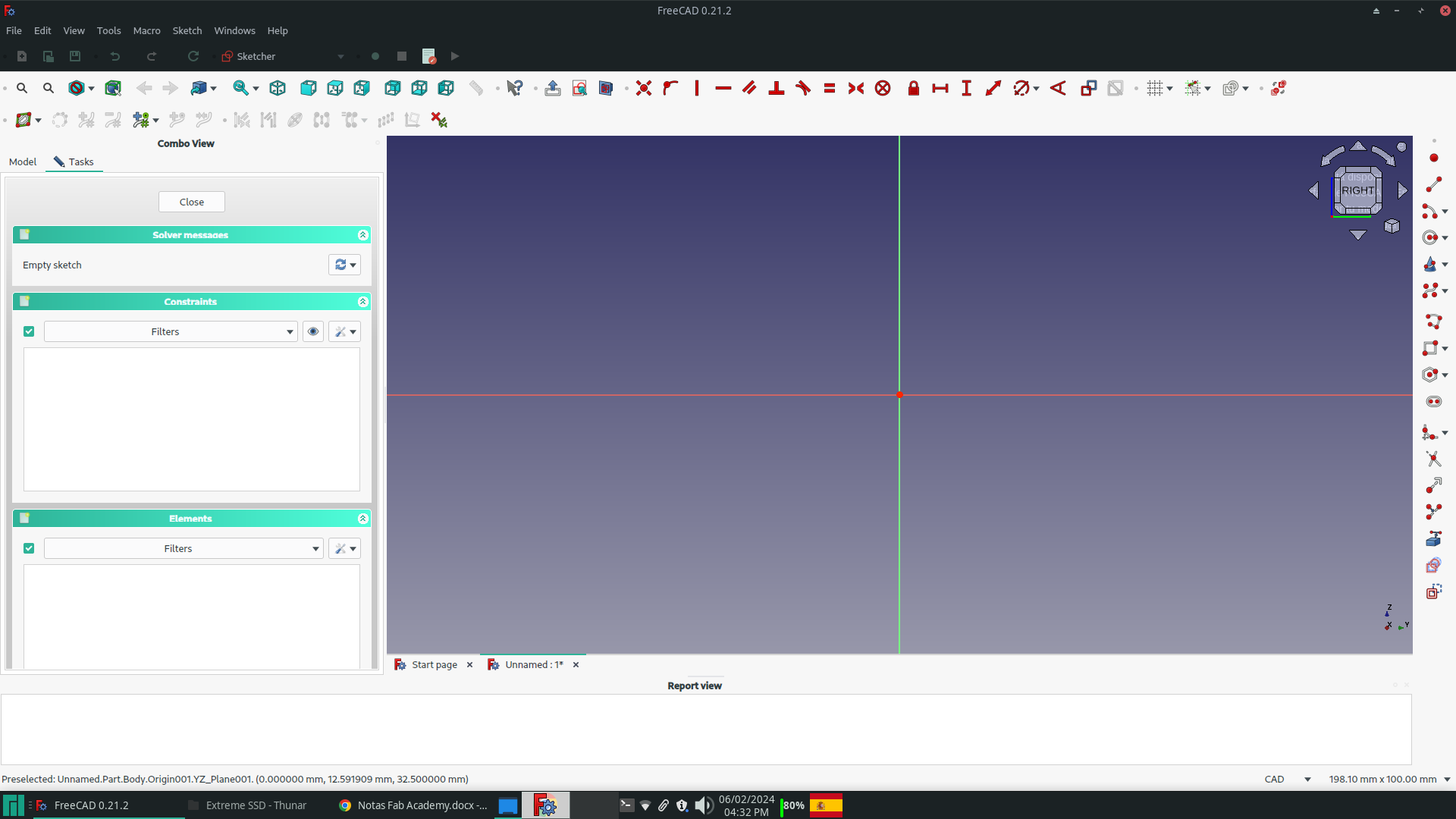
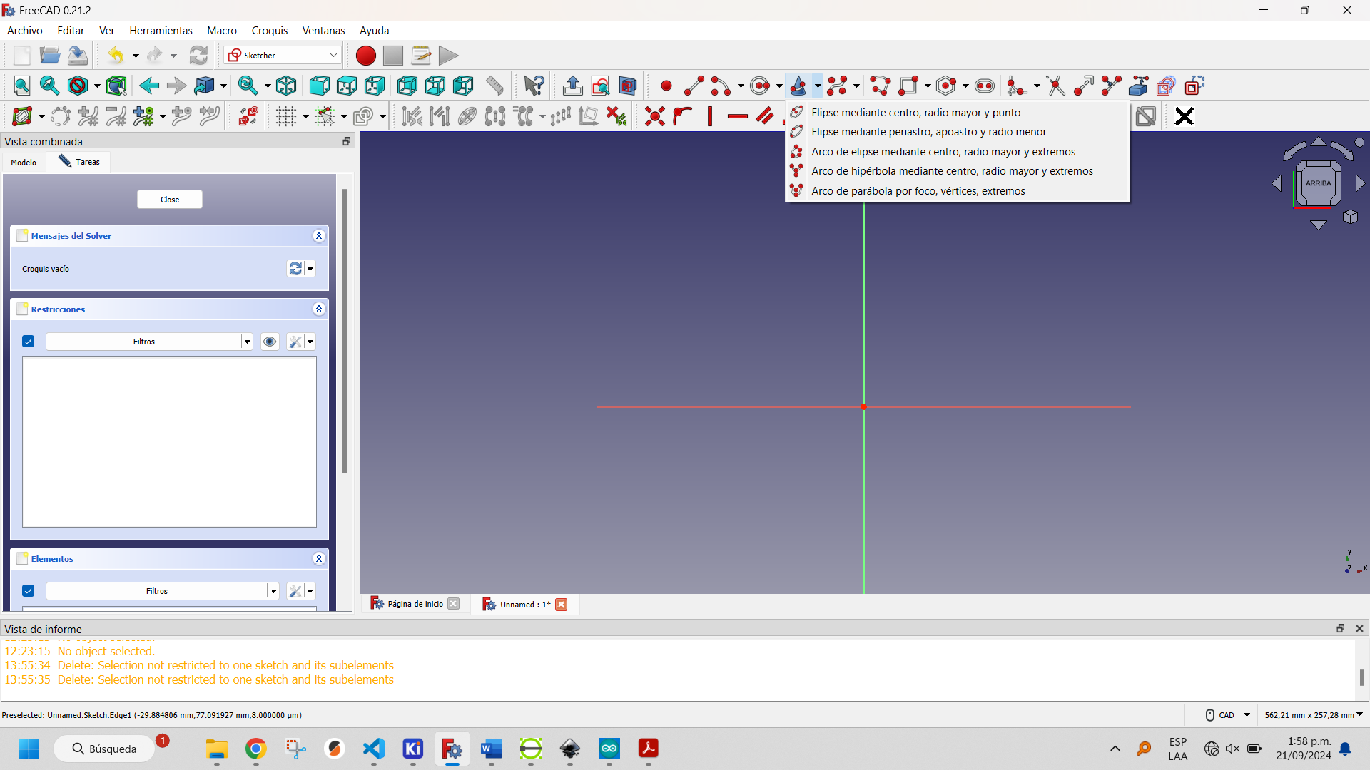
To begin drawing, utilize the drawing tools found in the workbars, such as Sketcher geometries or Sketcher constraints. These are just two examples of the available tools.
For the beach design, I created an equilateral triangle with the Sketcher Geometries toolbar's Triangle button. The triangle has its center at the selected point and is inscribed in a circle whose radius is determined by the choice of a second point.
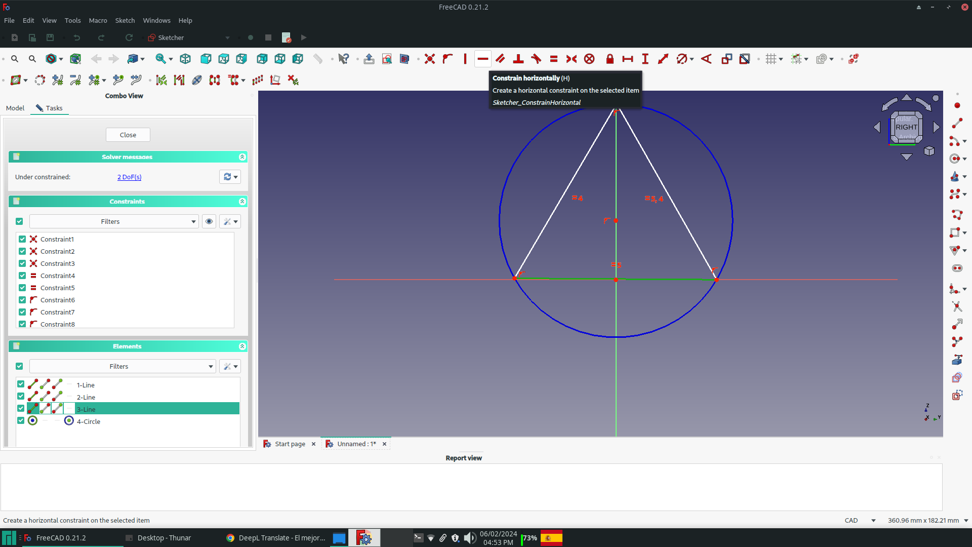
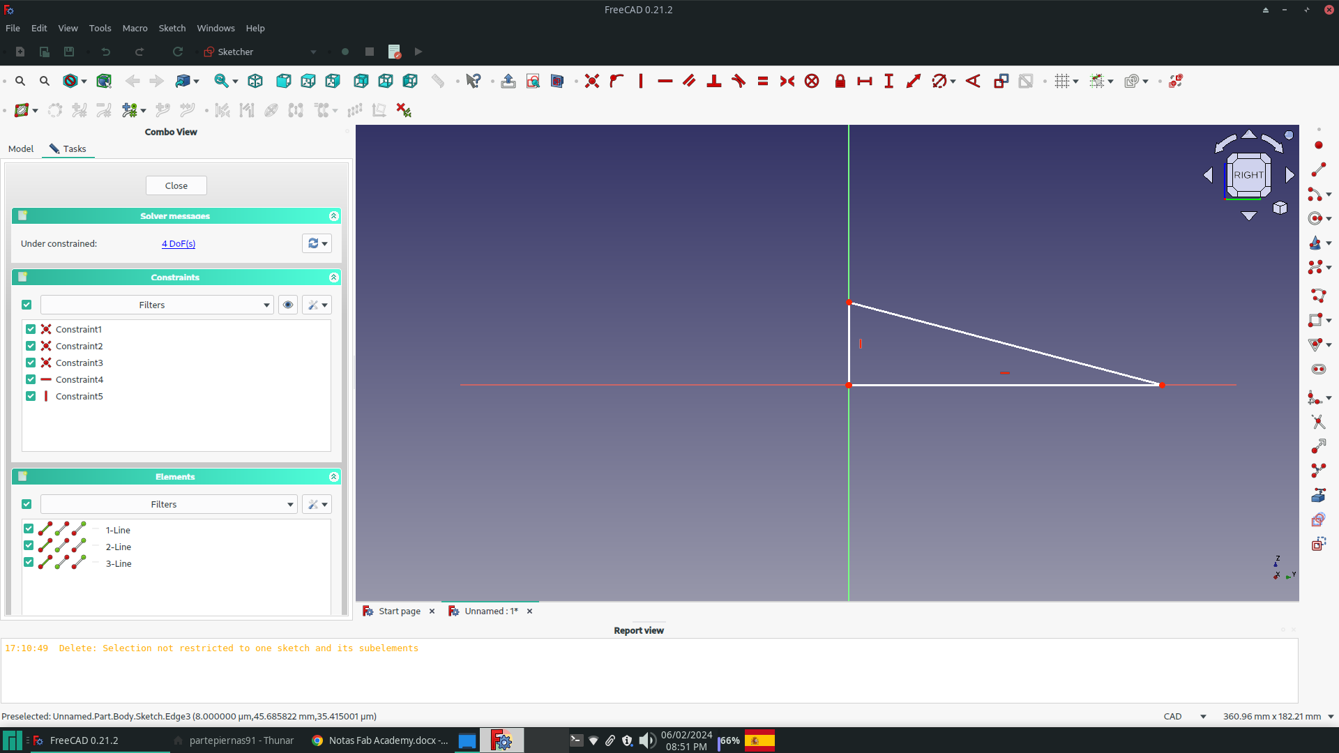
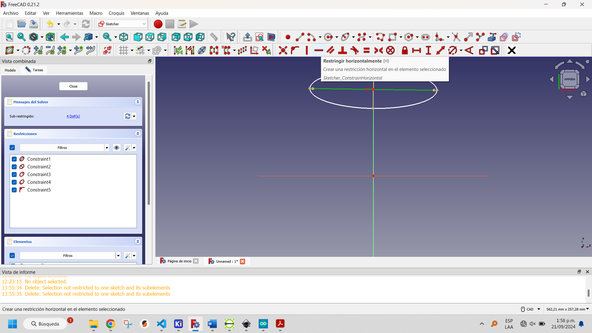
I removed the equality constraints from the three sides and added the vertical constraint to the right side, resulting in the right triangle required.
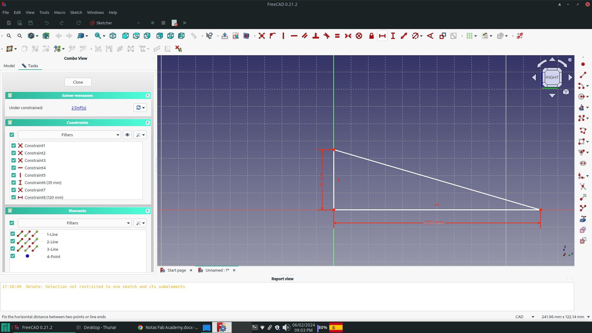
The triangle's legs were then constrained vertically and horizontally to 35 mm and 120 mm, respectively, using the buttons on the Sketcher Constrains toolbar.The triangle's legs were then constrained vertically and horizontally to 35 mm and 120 mm, respectively, using the buttons on the Sketcher Constrains toolbar.
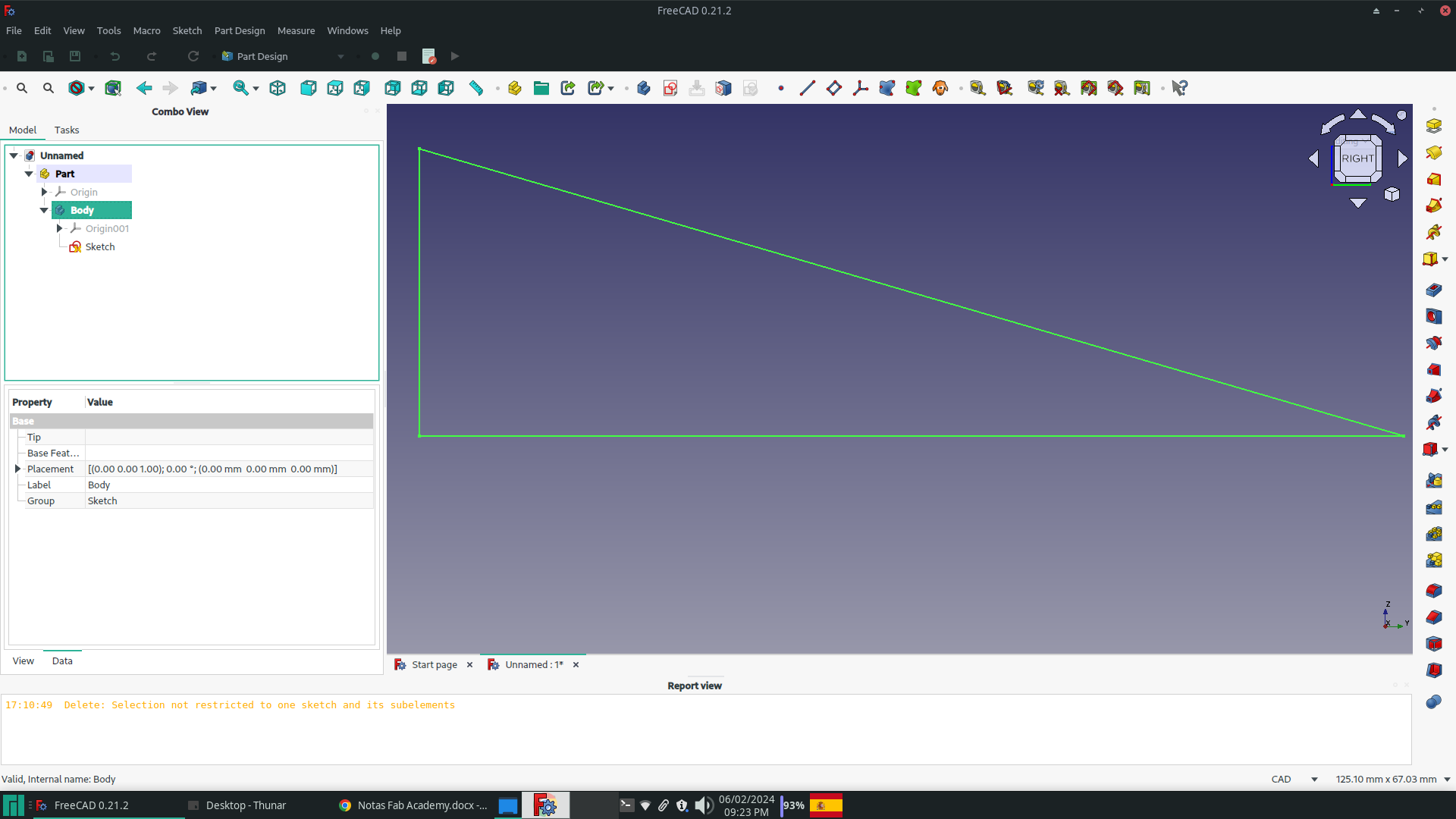
Click on the Close button in the Tasks window to exit the Sketch view and enter the Part Design view. In the Model window, select the sketch you want to extrude and mark it. This will allow you to proceed with the extrusion process.
To begin the extrusion process, select the Pad button located on the Part Design Modeling toolbar. Fill in the parameters of the Tasks window with a width of 20 mm, ensuring symmetry with respect to the plane, and a Taper Angle of 15º.

An orthohedron measuring 35x20x5 mm was added to the bottom of the beach using the steps described above. The orthohedron was then united with the beach using the Union button in the Boolean bar of the Workbench Part.
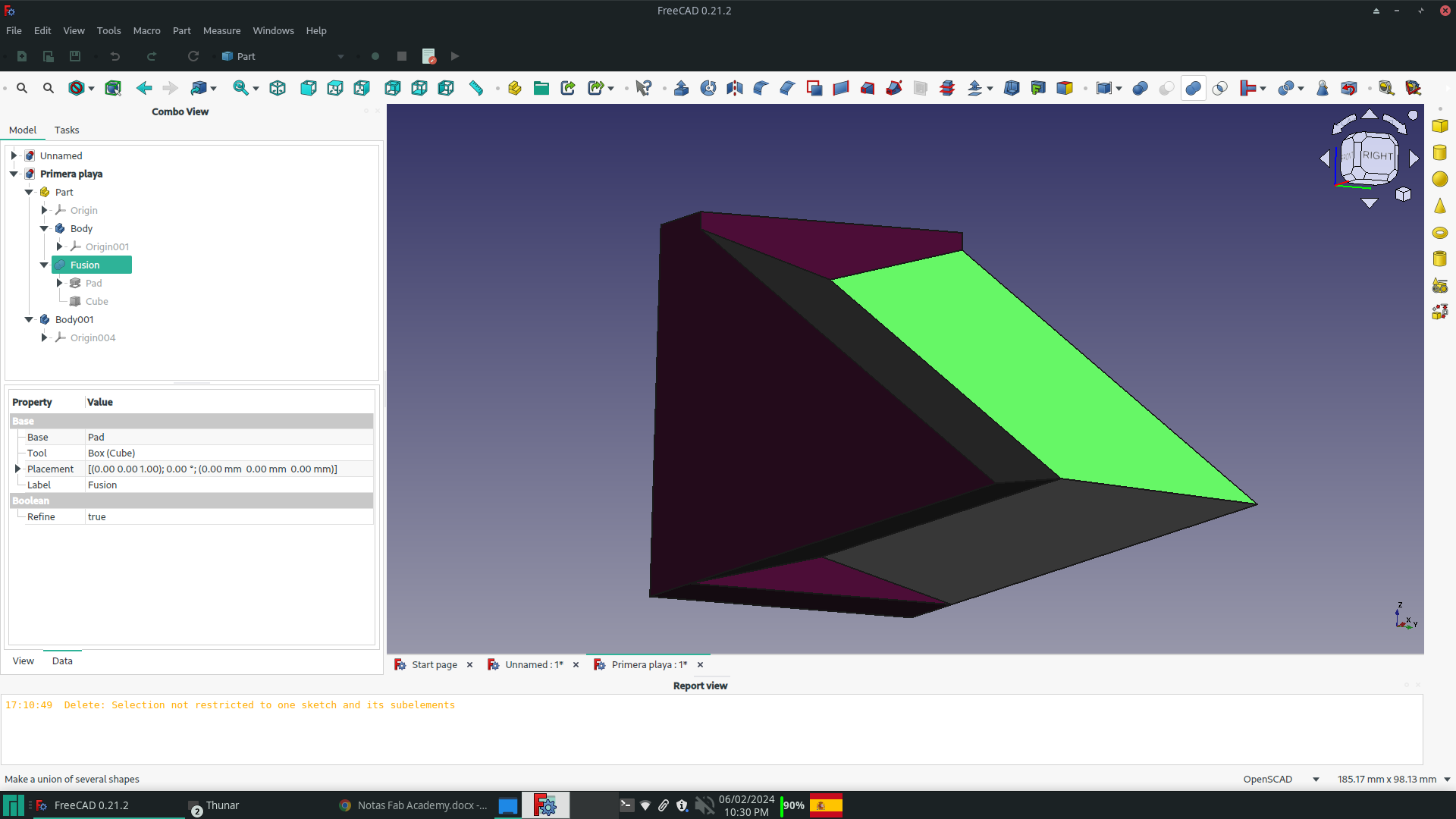
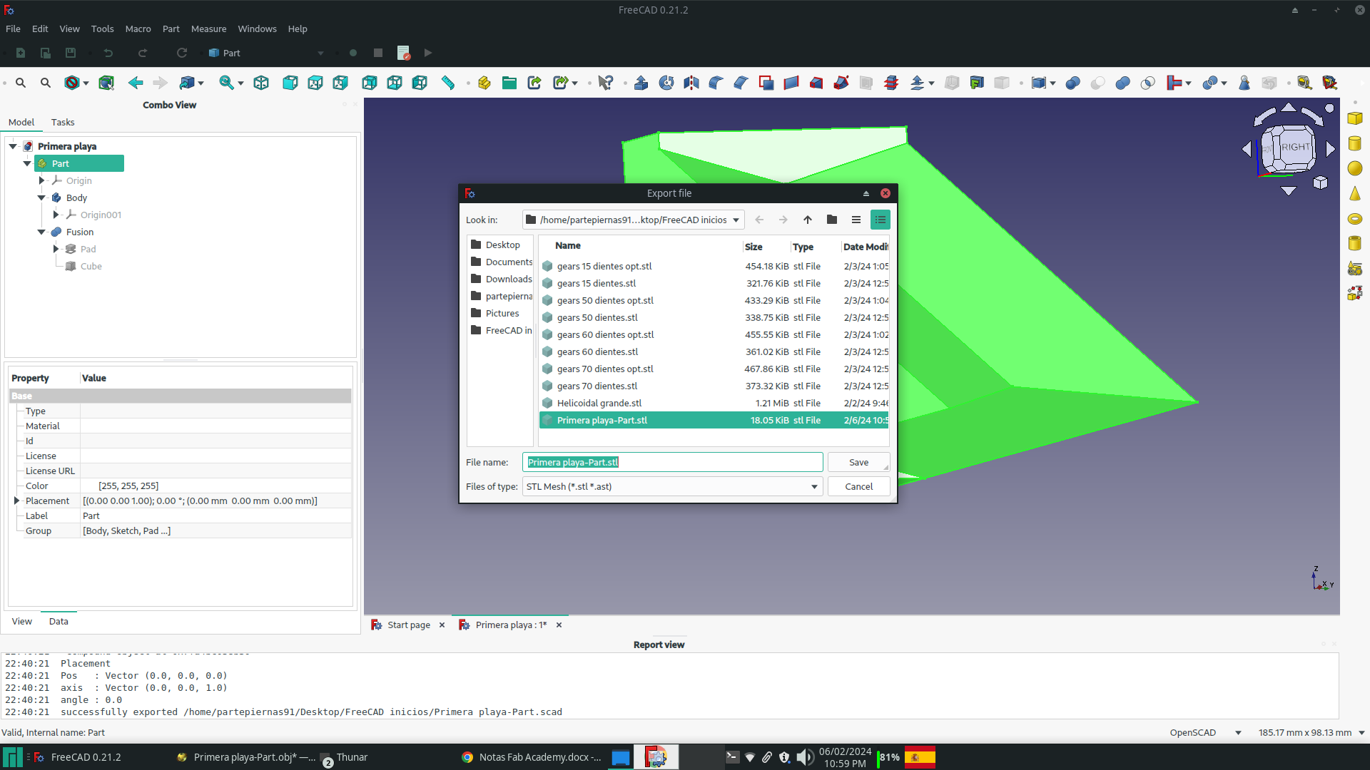
The body was exported to STL Mesh (.stl) format for opening with OpenSCAD.
More information about how to use FreeCAD can be found here.
OpenSCAD is a powerful open-source software for creating 3D models using a programming language rather than a graphical interface. One of its key advantages is the ability to leverage mathematical principles to design complex objects. By using mathematical equations and geometric concepts, users can precisely define the dimensions, shapes, and relationships within their designs.
The use of mathematical operations such as union, difference, and intersection allows for the creation of intricate and precise models. This approach provides a high level of control and accuracy in the design process, making it particularly suitable for engineers, mathematicians, and designers who require exact specifications in their 3D models.
Furthermore, OpenSCAD's reliance on mathematical principles enables parametric design, where objects can be easily modified by adjusting variables within the code. This facilitates rapid iteration and customization without the need to manually redesign each variation, saving time and effort in the design process.
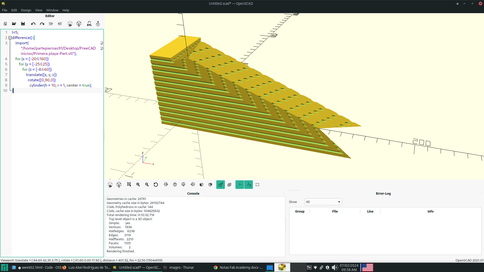
To test various configurations, the team created holes of different diameters on the beach using a cylinder matrix in OpenSCAD, as shown in the following code:
         l=5;

          difference() {
              import("/home/partepiernas91/Desktop/FreeCAD inicios/Primera playa-Part.stl");
              for (x = [-20:l:160])
                  for (y = [-25:l:25])
                      for (z = [-8:l:60])
                          translate([x, y, z])
                            rotate([0,90,0])
                              cylinder(h = 10, r = 1, center = true);
           }
The design's final version is presented below:
2D desings
To make 2D designs I decided to try three programs and compare results. These are FreeCAD, InkScape and LibreCAD. The main idea is make the same desing in this programs to compare results. The design to be carried out is based on the following sketch, which represents the trajectories followed by the particles of a fluid at different depths for waves of intermediate relative depth, according to Airy's Linear Wave Theory:
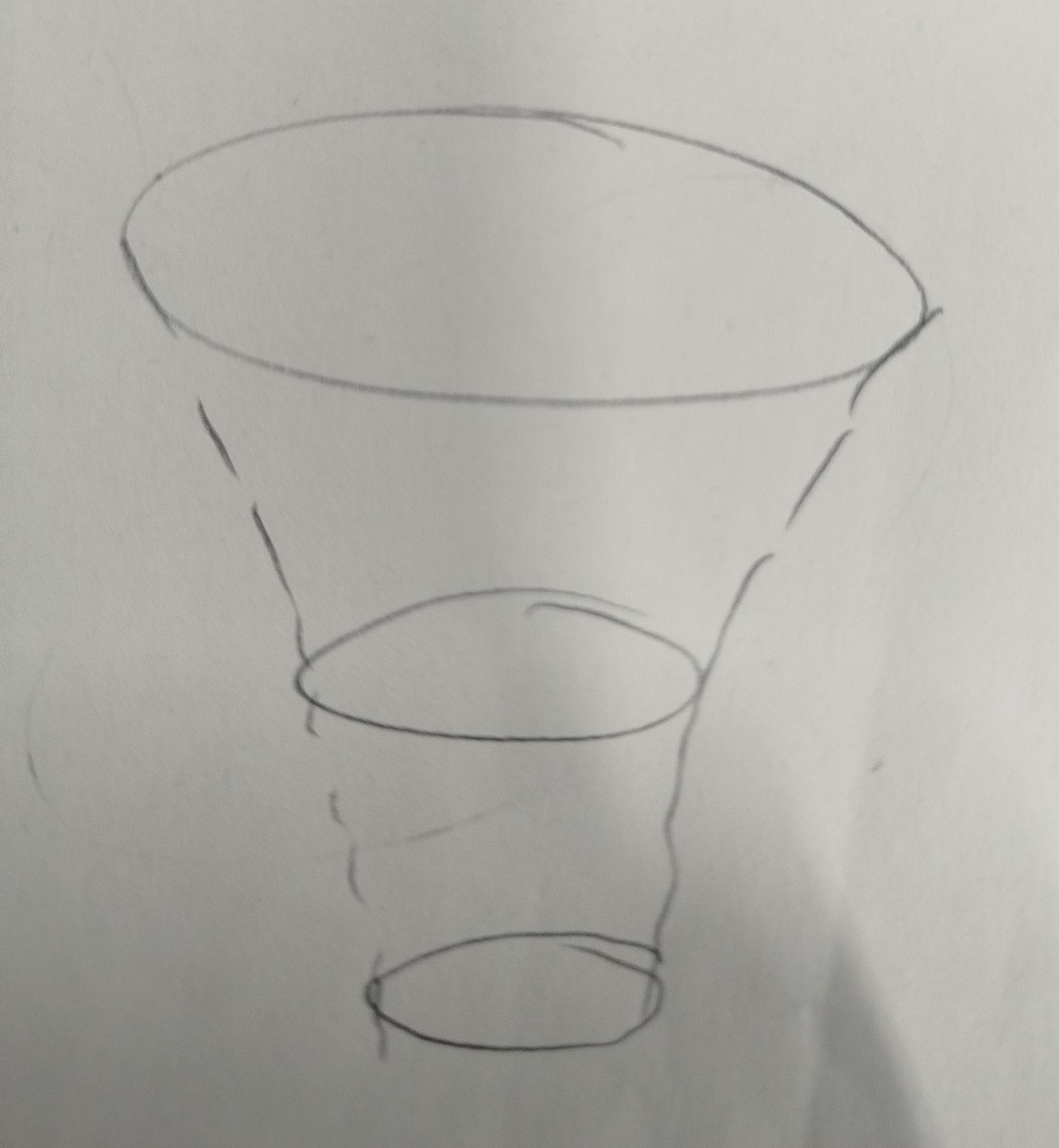
Sketch of logo to be designed
|
|
|
|
| Sketcher Workbench logo of FreeCAD | Inkscape logo | LibreCAD logo |
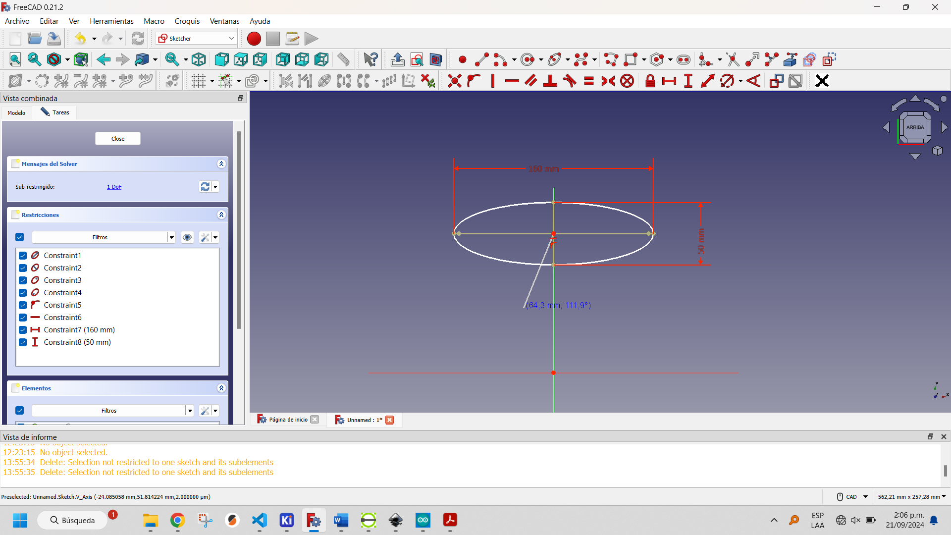
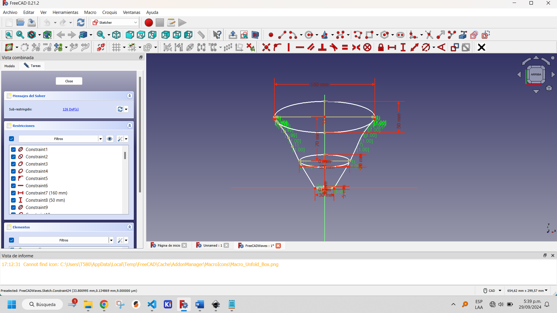
As I said before, FreeCAD is a 3D design program, but it has 2D design tools that can be used for 3D design or not, depending on the needs at hand. To make 2D designs, the Sketcher and Draft Workbenches are used, but I will only make mention of the Sketcher Workbench. At the beginning of the page you can find some examples of how to use it, so I will focus in this space on addressing its features.
Sketcher Workbench allows vectorial designs and has tools for drawing basic geometric figures such as regular polygons and polygonal lines, second degree curves with their respective arcs, B-spline, polylines, among others. For each sketch there are two types of objects: elements and constraints. Elements are the objects that will appear in the drawing and that will constitute it. Constraints are objects that allow a correct construction of the elements, allowing to dimension lengths, angles, parallelism, perpendicularity, equality, among others. An important difference between this program and others dedicated exclusively to 2D design is that the dimensions are not drawn in the final result. Another, somewhat more significant difference is that it is not possible to add text directly: it must be exported or designed with lines from scratch.
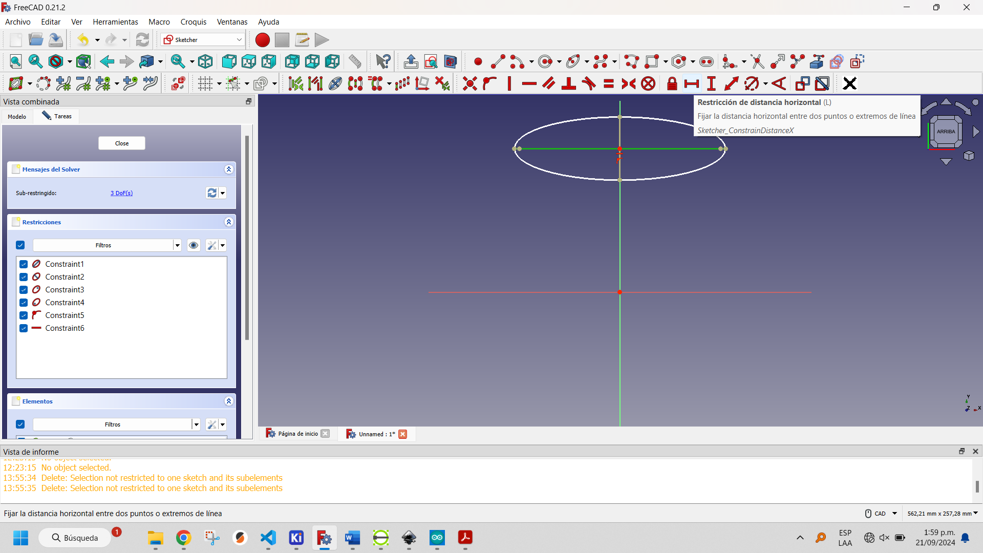
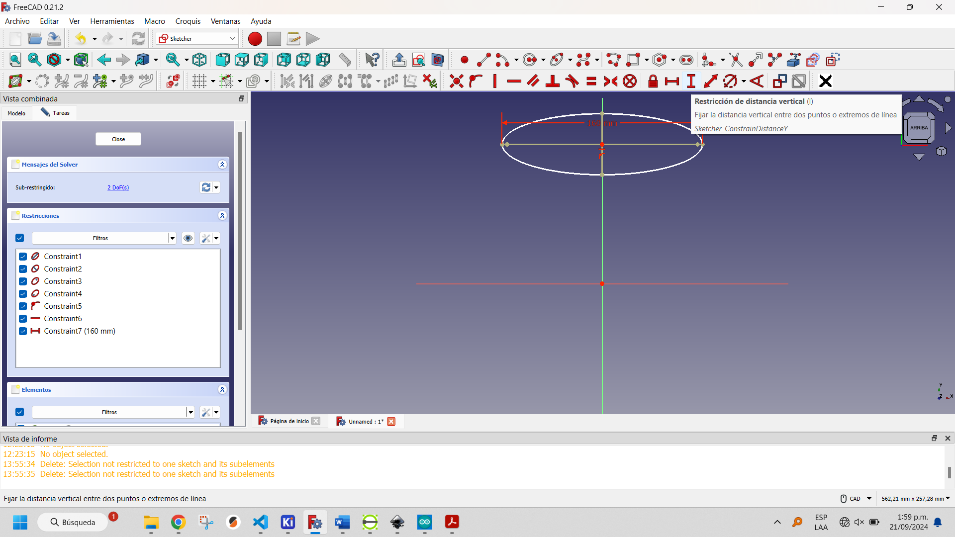
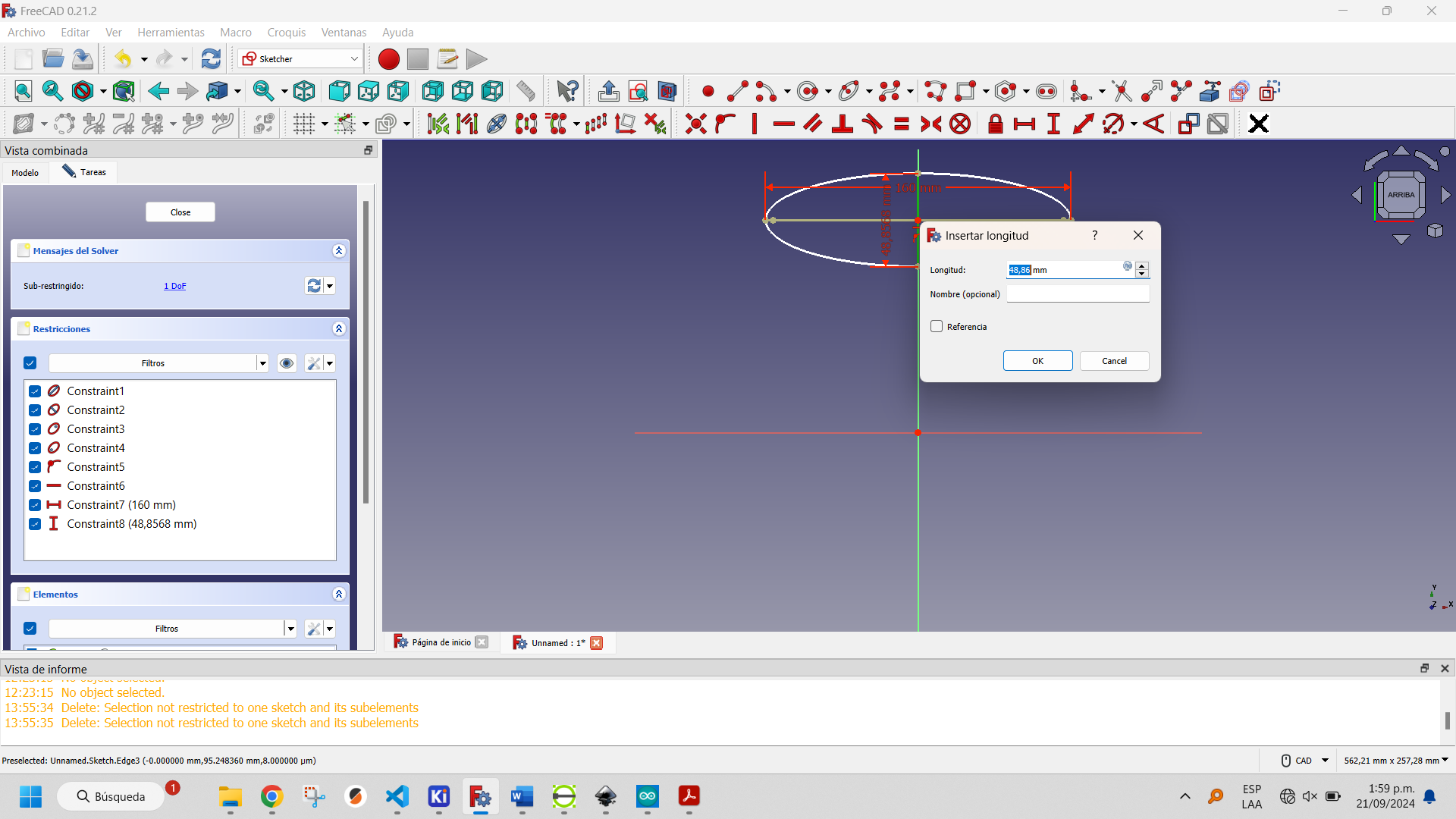
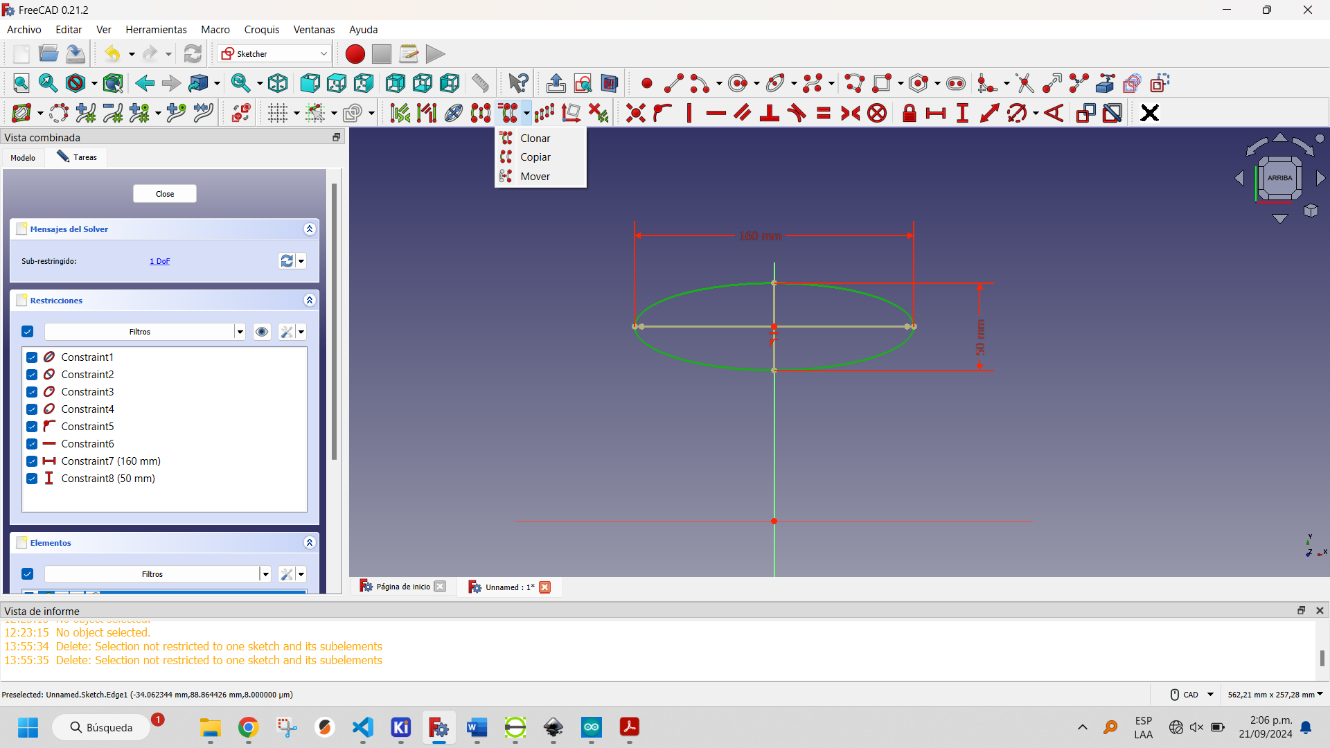
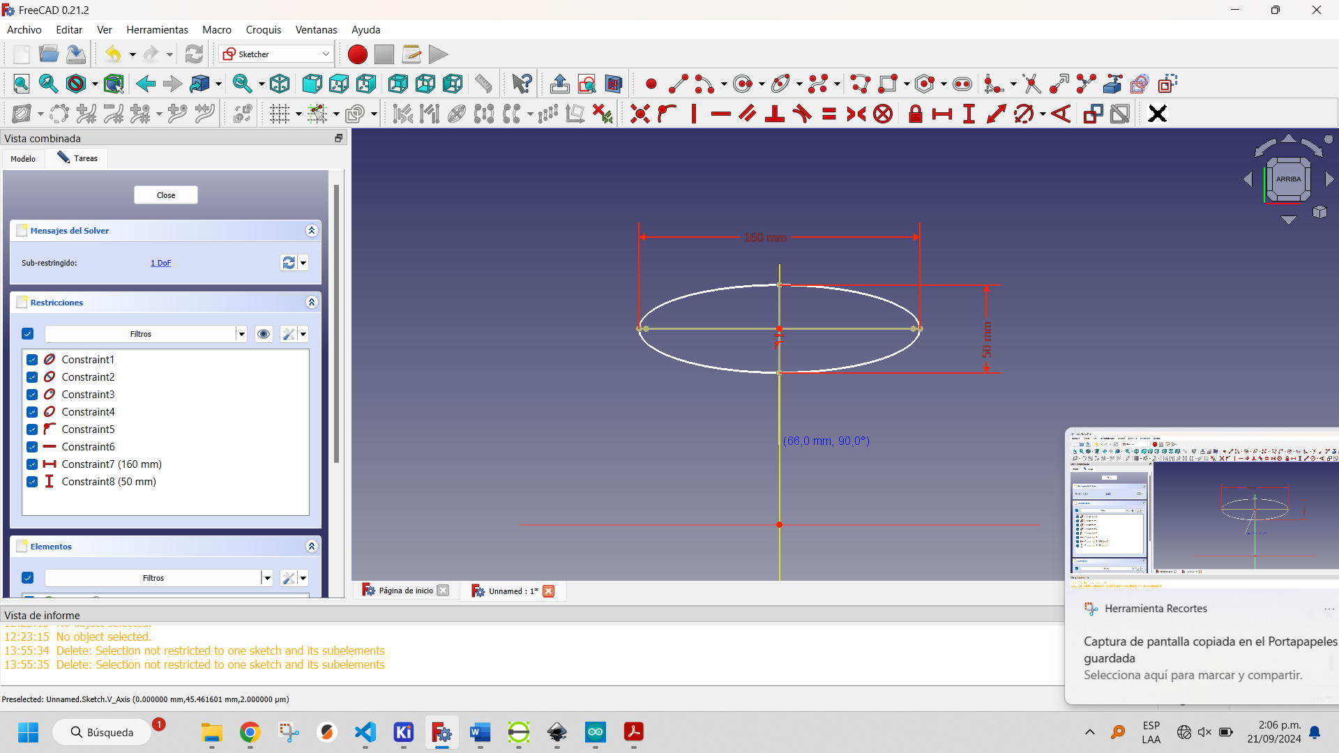
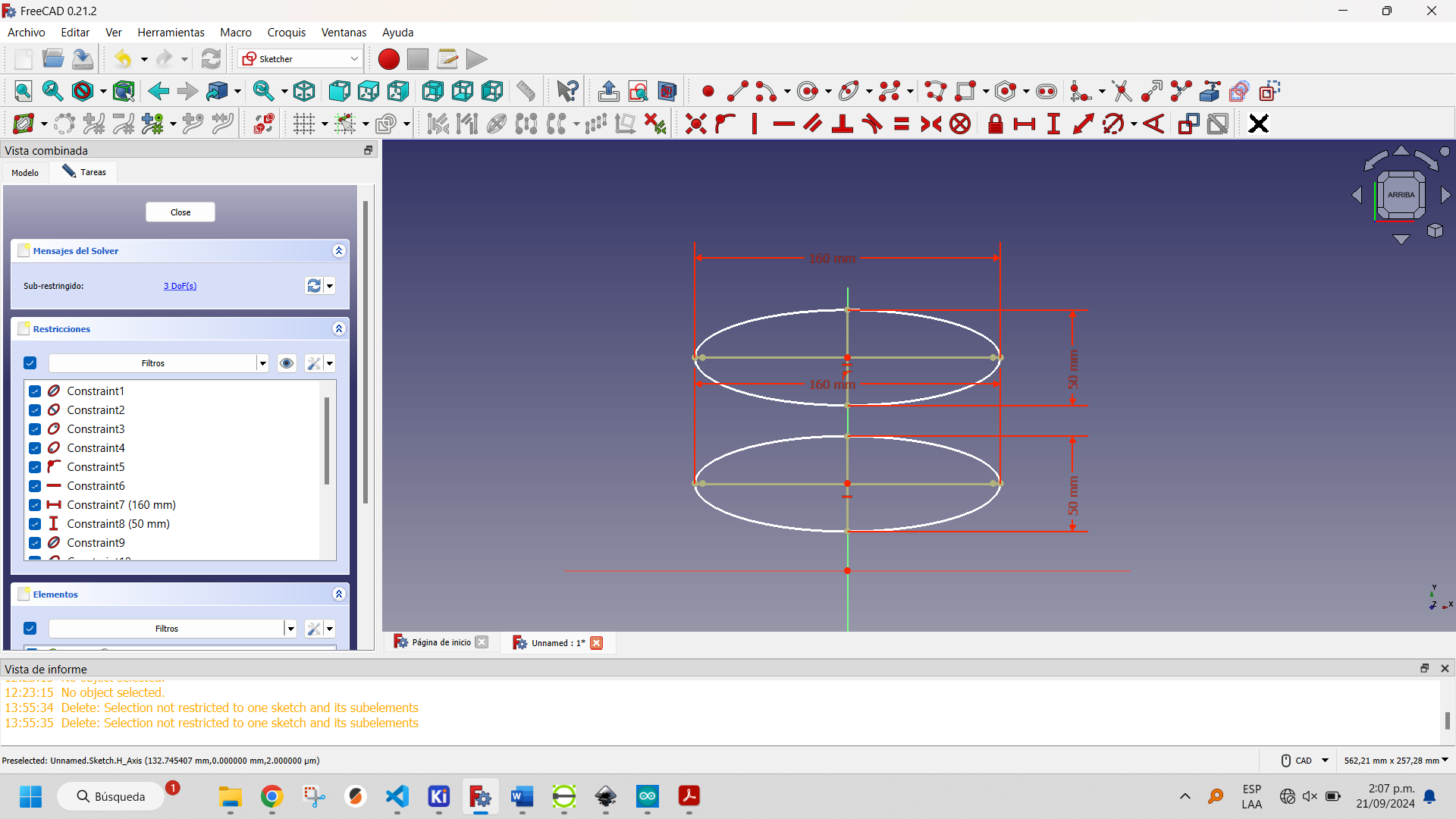
The following images show the step-by-step creation of the drawing and the tools used:

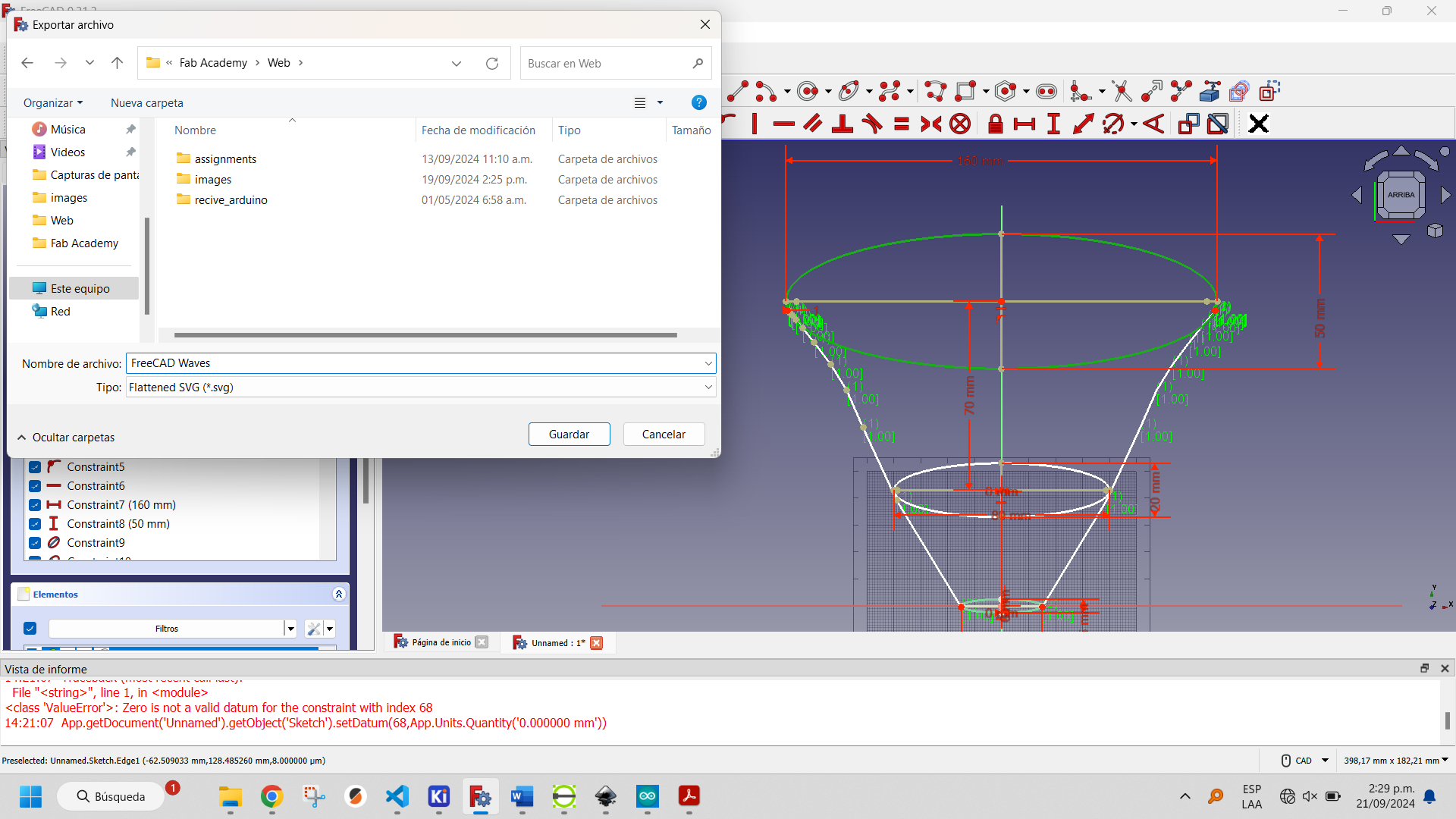
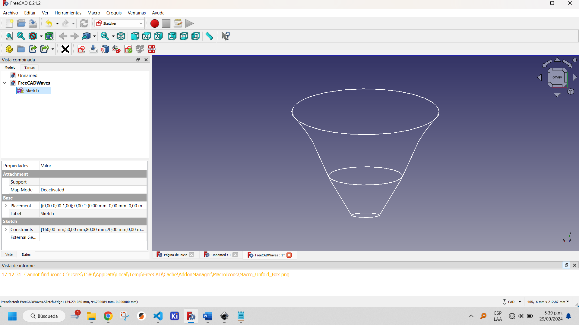
The the final result is show below:

The files generated by FreeCAD can be downloaded by clicking the button below.
More information about how to use Sketcher Workbench of FreeCAD can be found here.
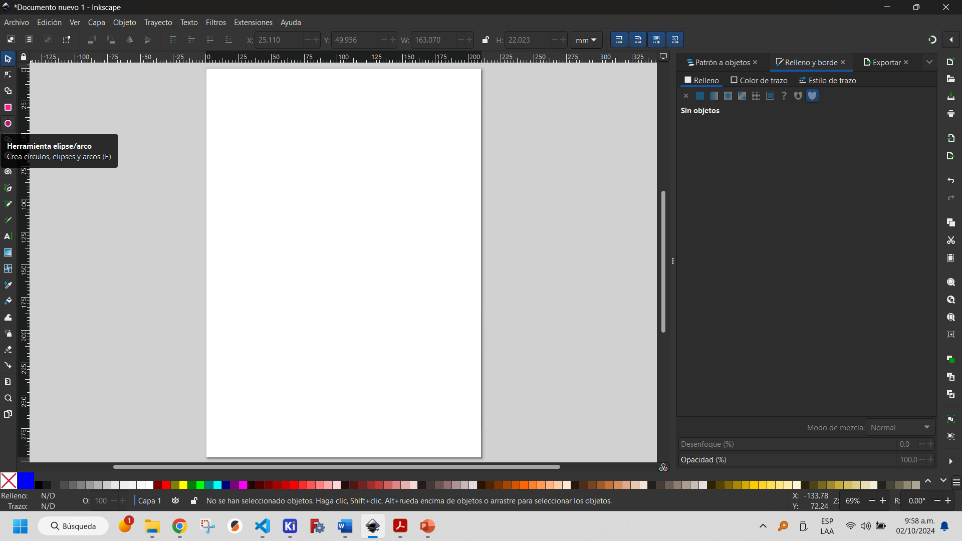
Inkscape is an open source graphic design software used to create and edit vector graphics. It allows you to create and modify vector-based images, which means they can be scaled without losing quality, offers various tools for drawing shapes, strokes and text, and supports multiple file formats, but its default file format is Scalable Vector Graphics (SVG).
The program also has the same tools for object construction, but without the constraints of the Sketcher Workbench of FreeCAD. These are shown below.
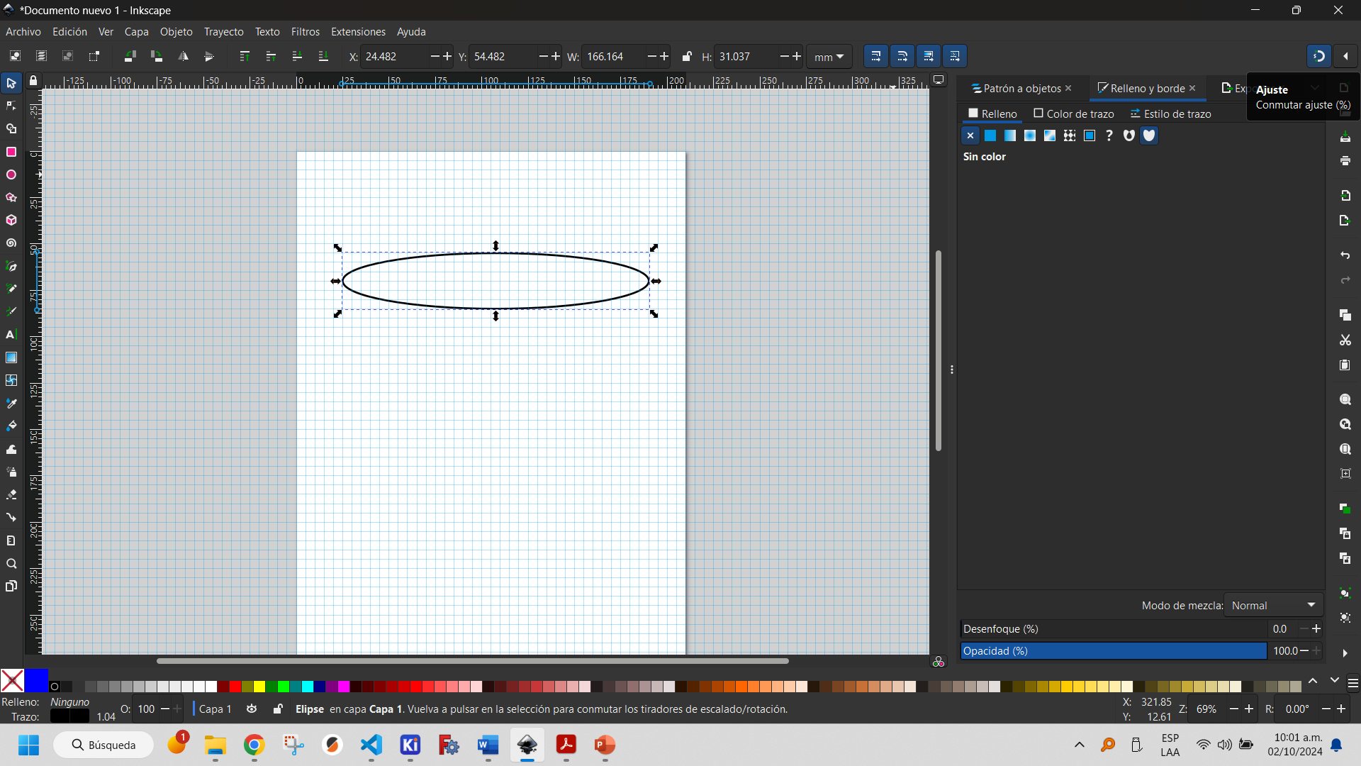
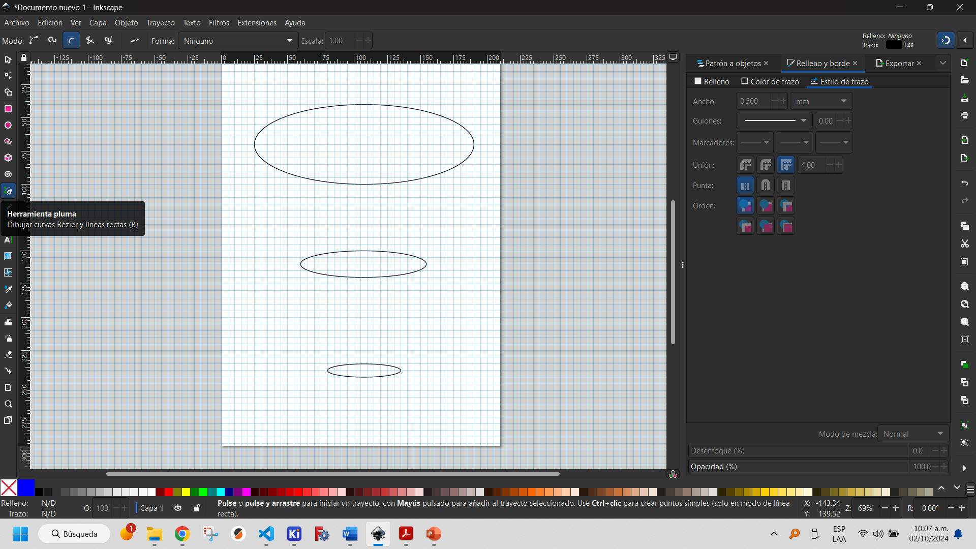
To create an ellipse, use the ellipse creation tool, which allows you to position it on the document.
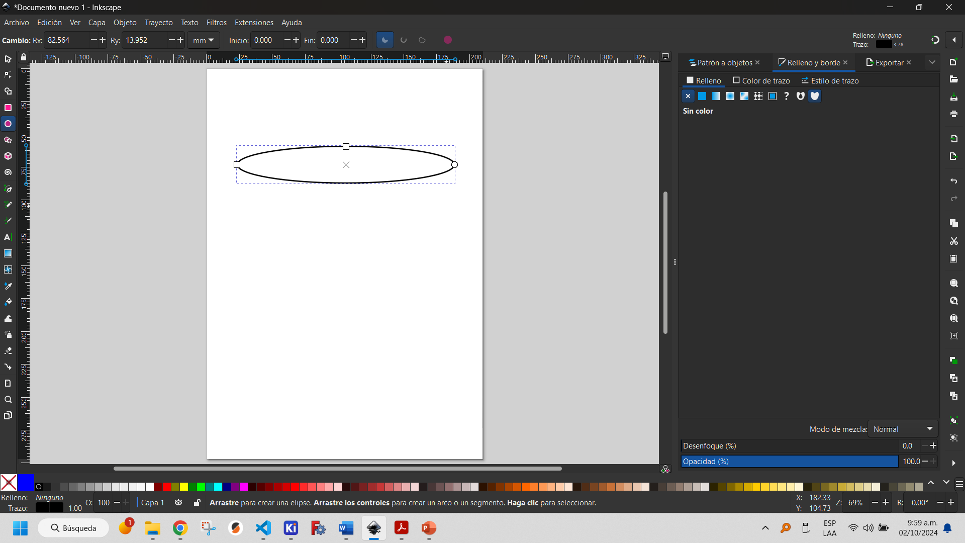
To facilitate the design process, it is convenient to make use of the page grid and the magnet to switch settings. The latter allows objects to be automatically aligned with other elements or guides, facilitating a precise and organized design.
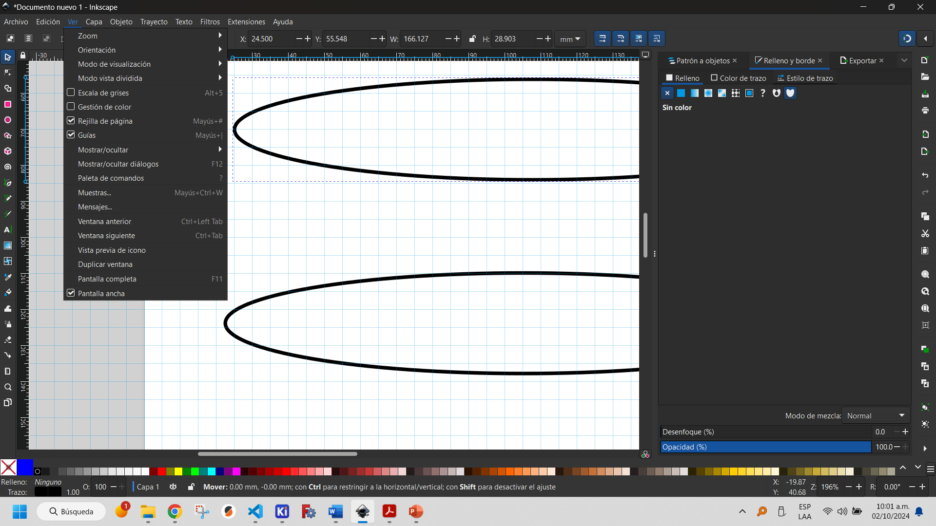
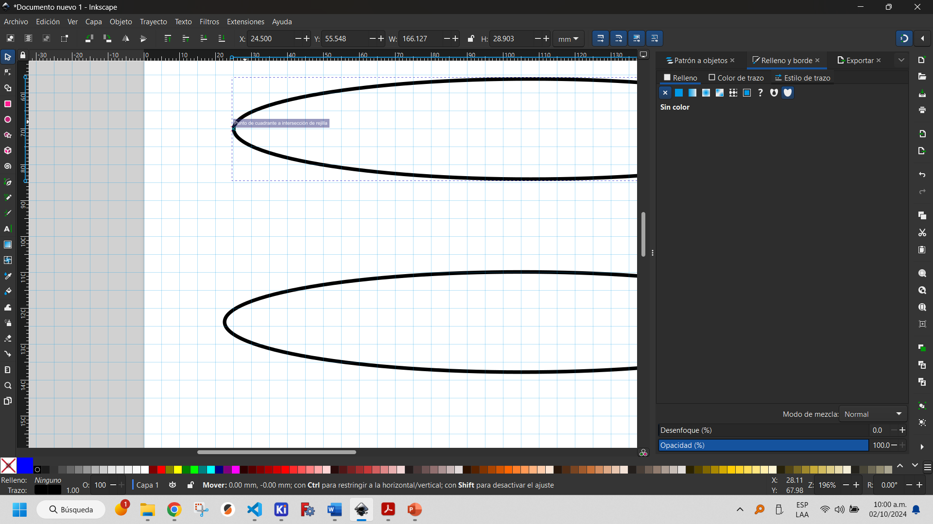
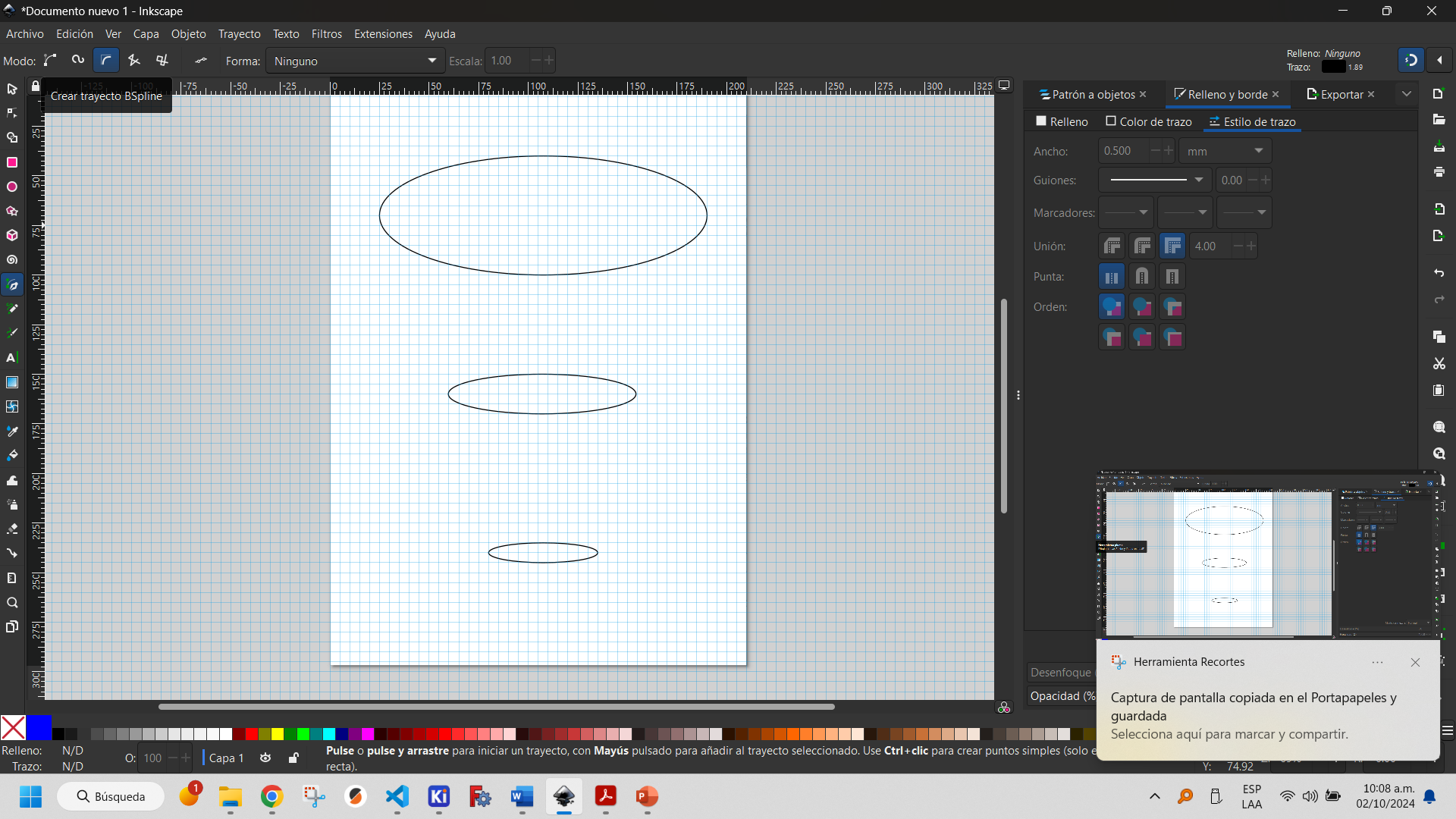
In the following image you can see how two objects are aligned for this reason. These objects are a duplicate, copying and pasting the first one (Ctrl+C and Ctrl+V).
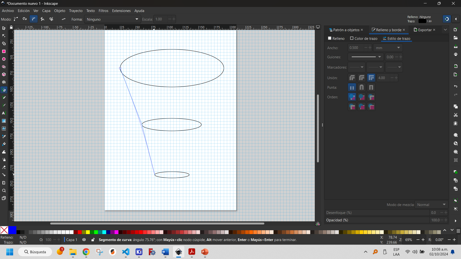
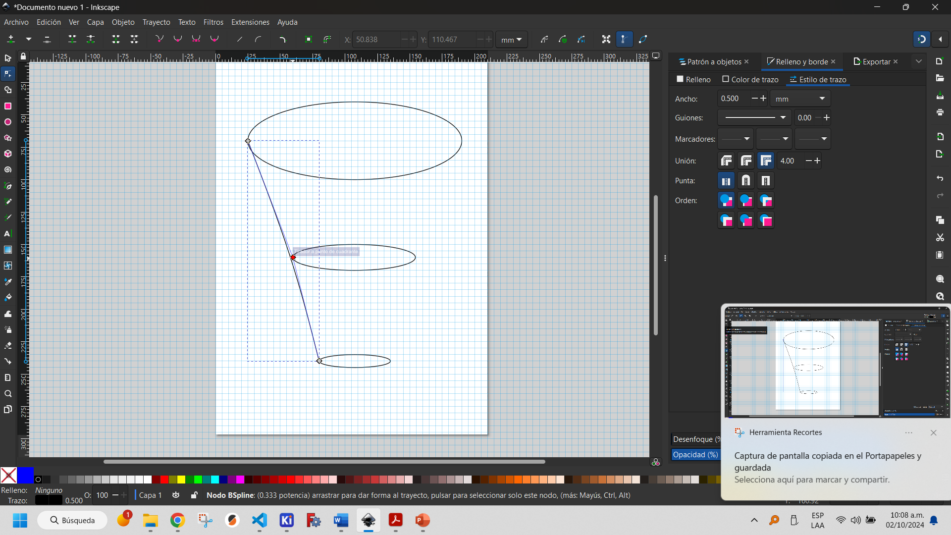
By using the pen tool and selecting the B-spline path type you can create curves with the desired shape.
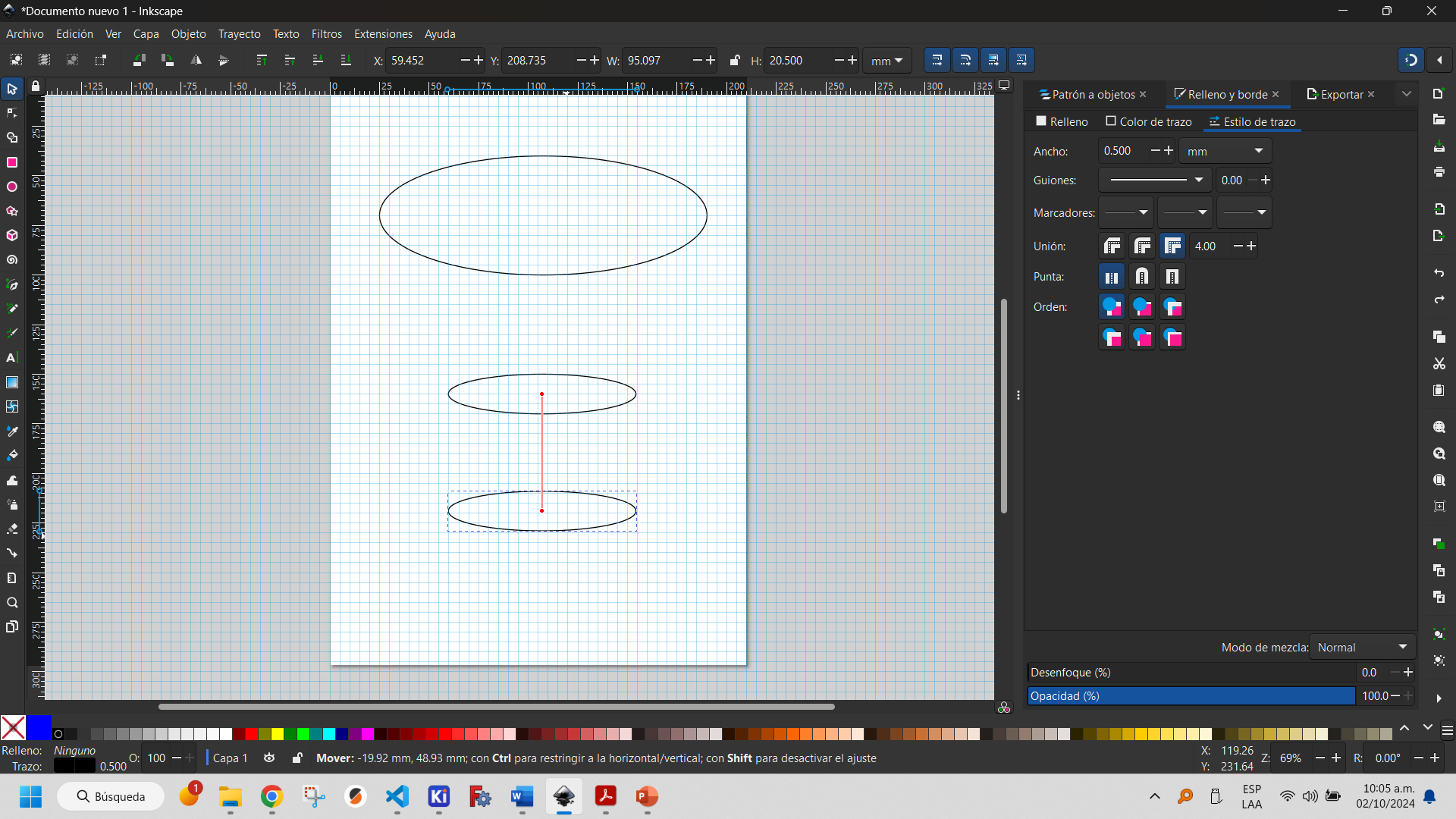
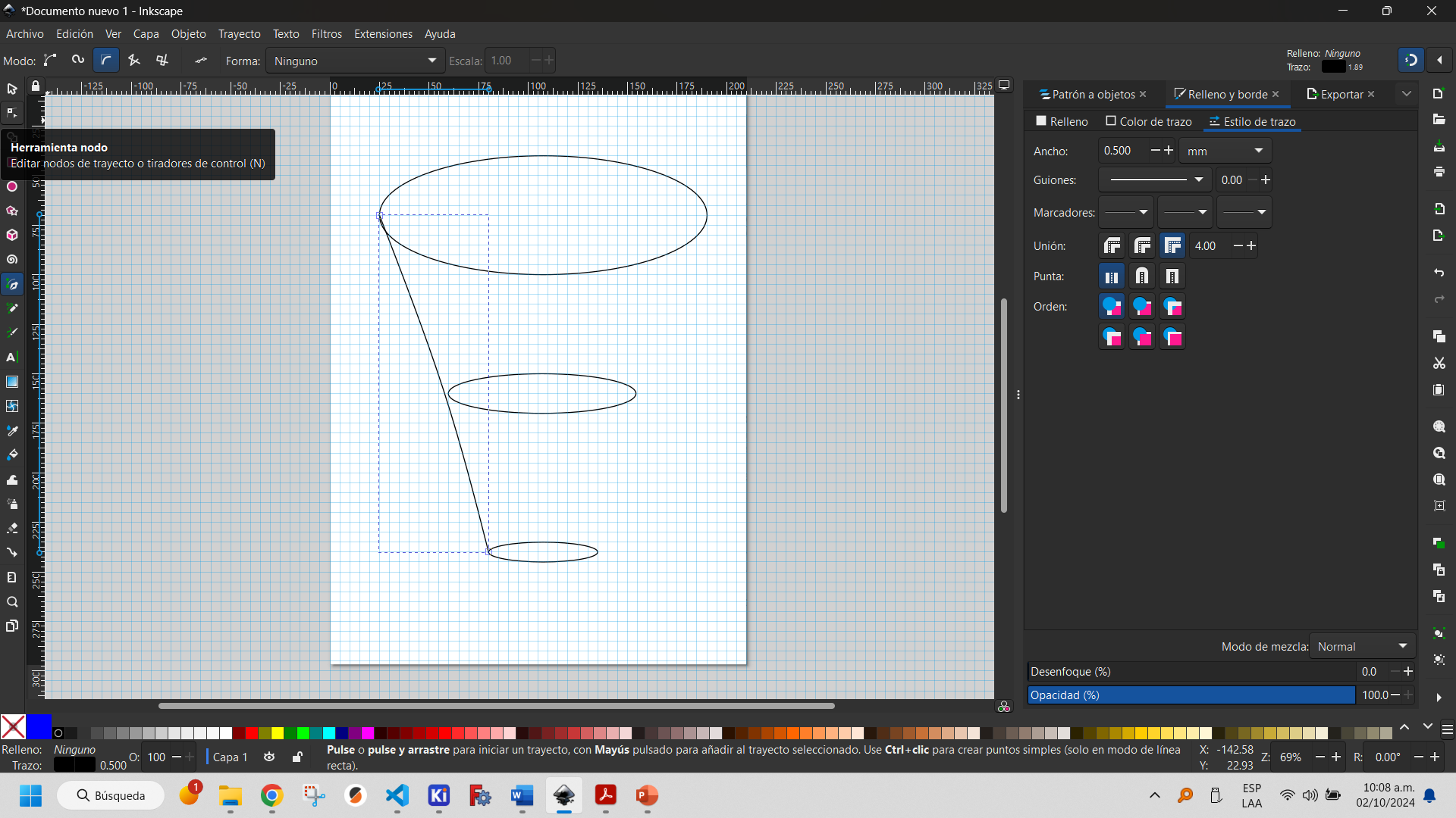
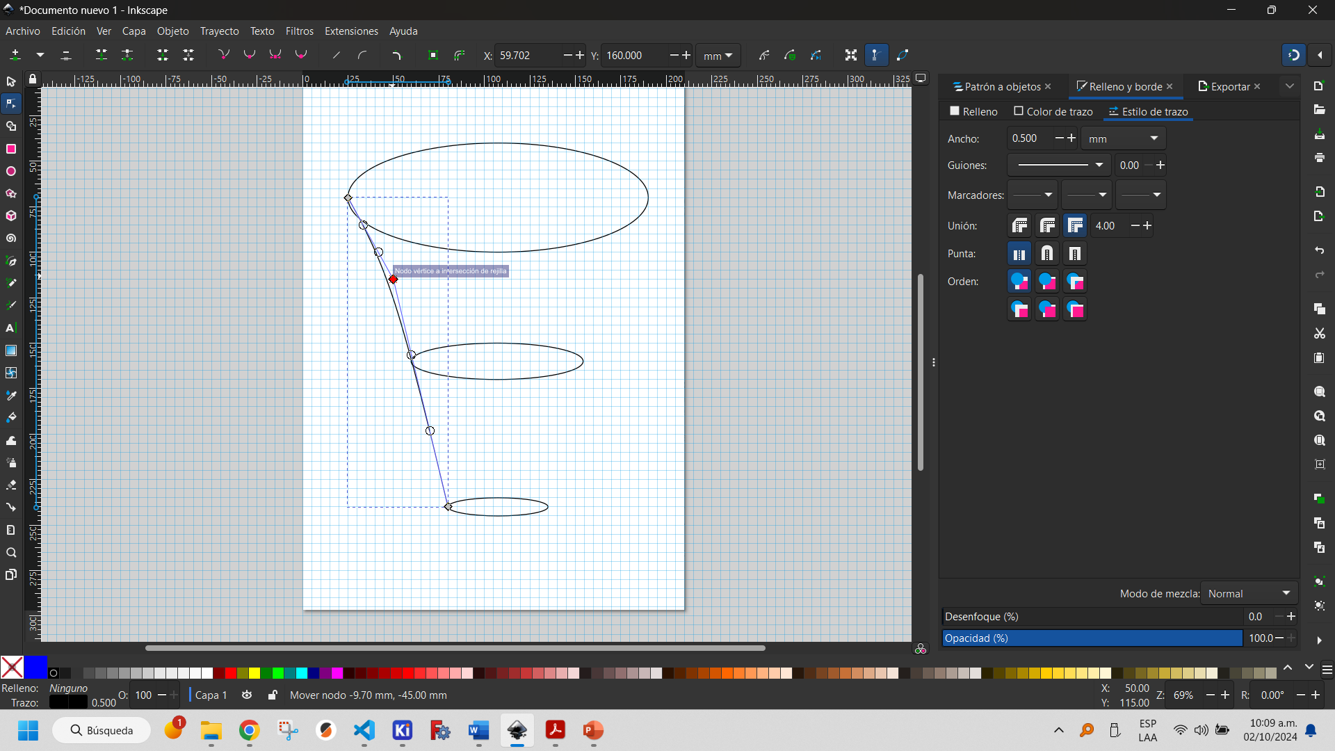
These curves can be adjusted with the node tool, which allows for better adjustments to the design.
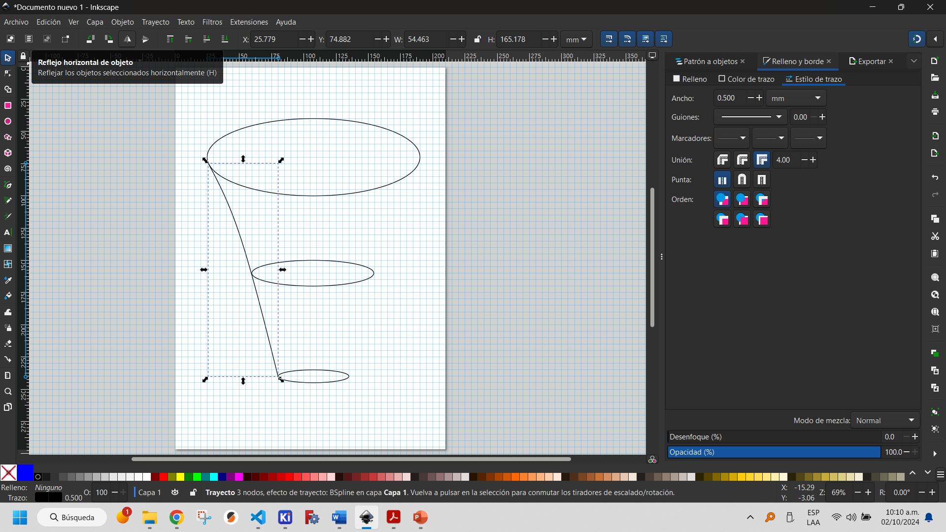
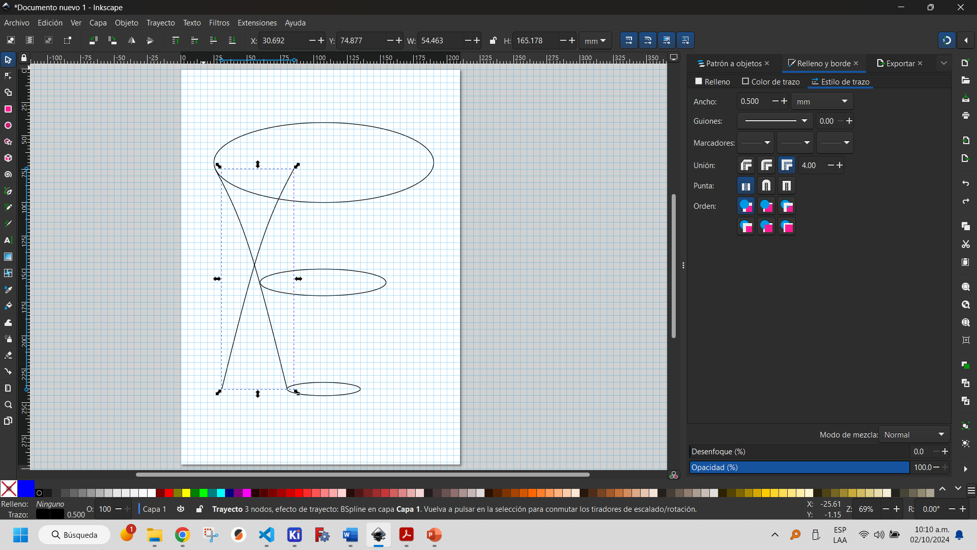
Tools for manipulation of the created objects are displayed in the upper left corner. I made use of one of them, the horizontal object reflection, which translates the object by applying a vertical reflection to it. Others allow you to apply other movement operations to the objects.

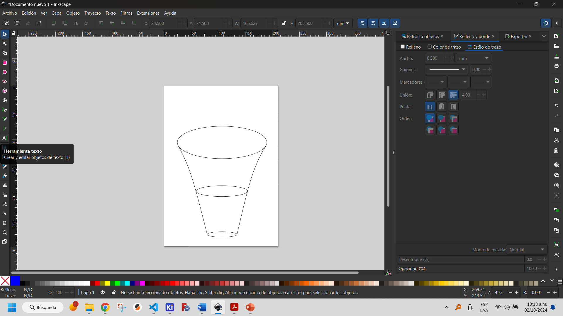
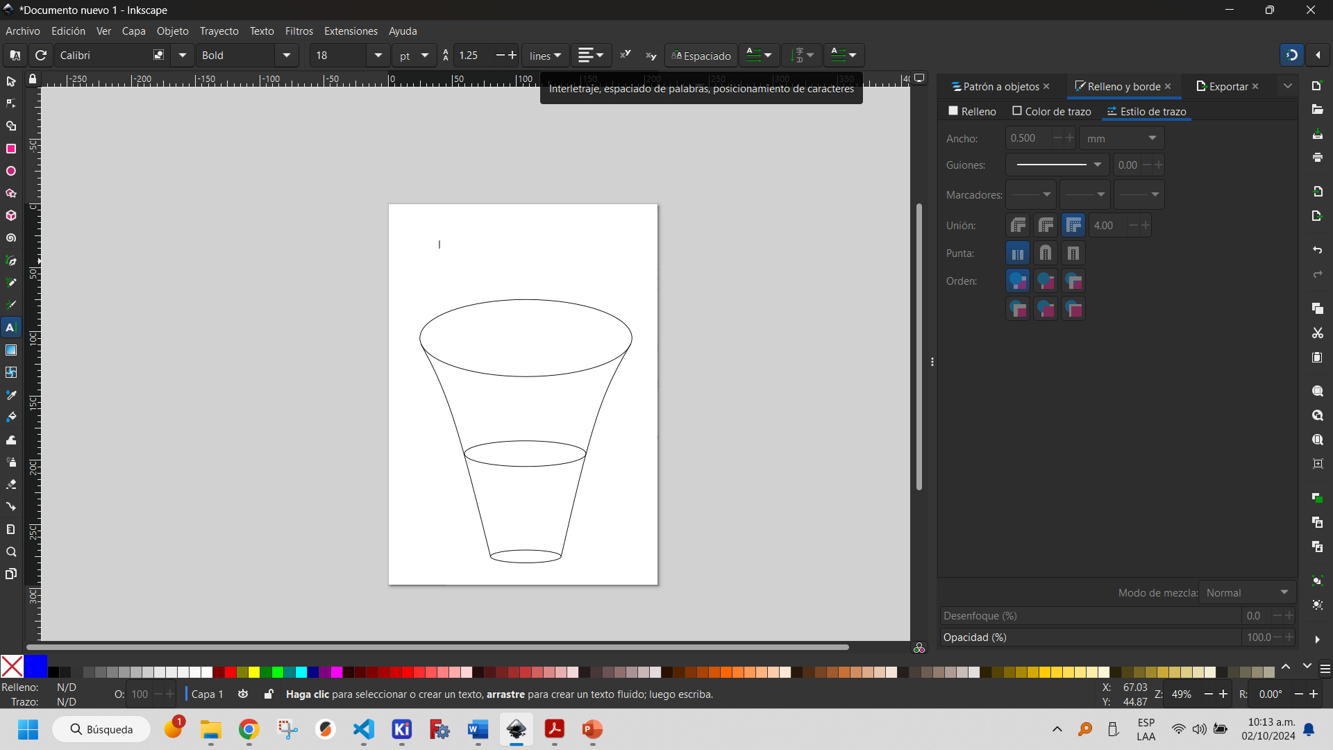
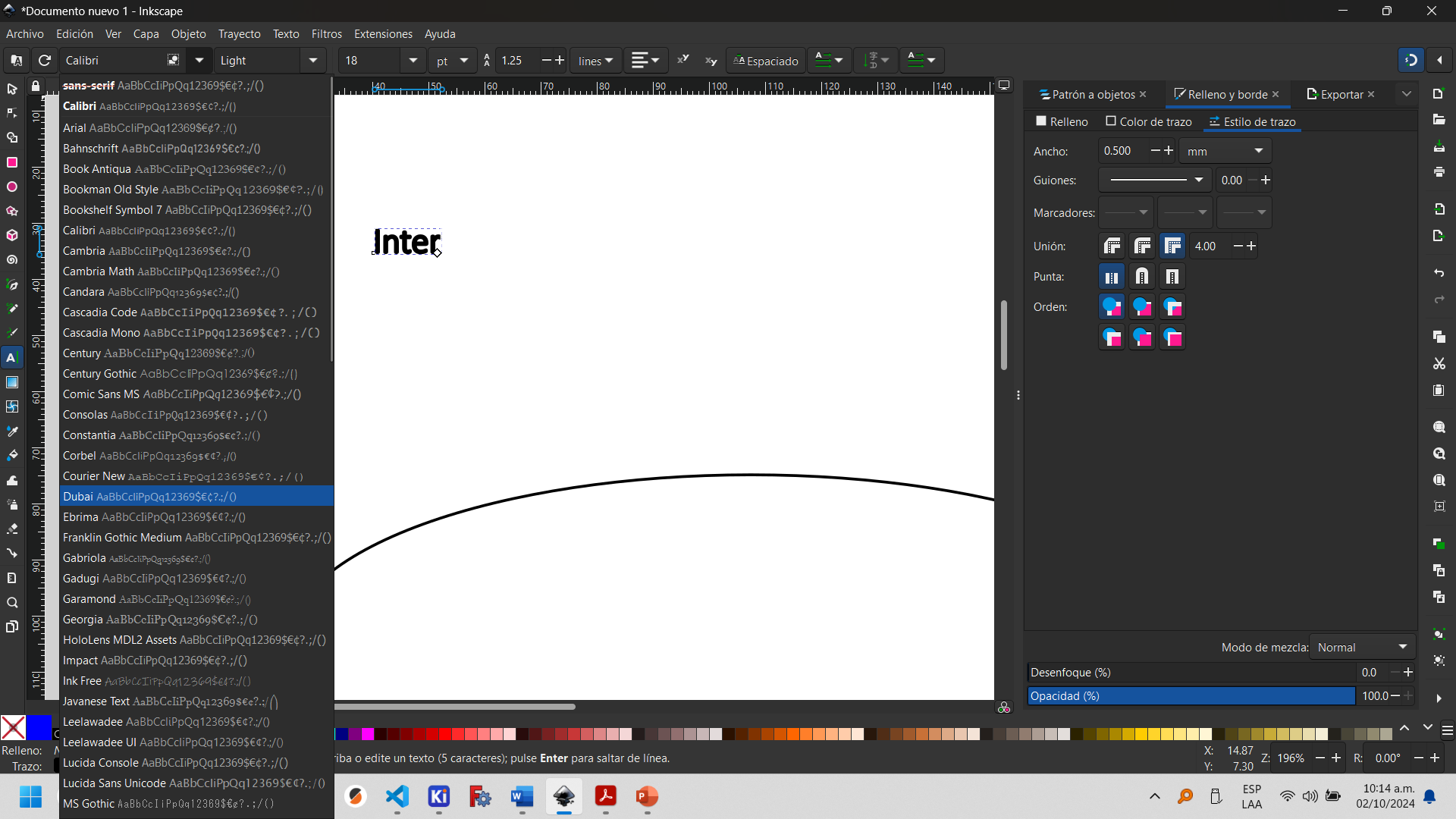
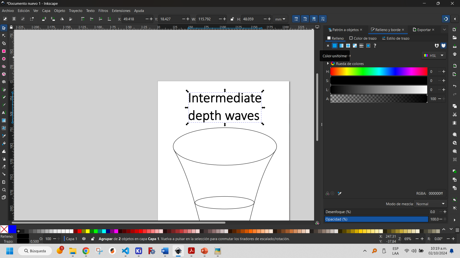
Inkscape has a text insertion tool that allows you to modify the parameters as if it were a text editor (font, size, typographic style, among others).
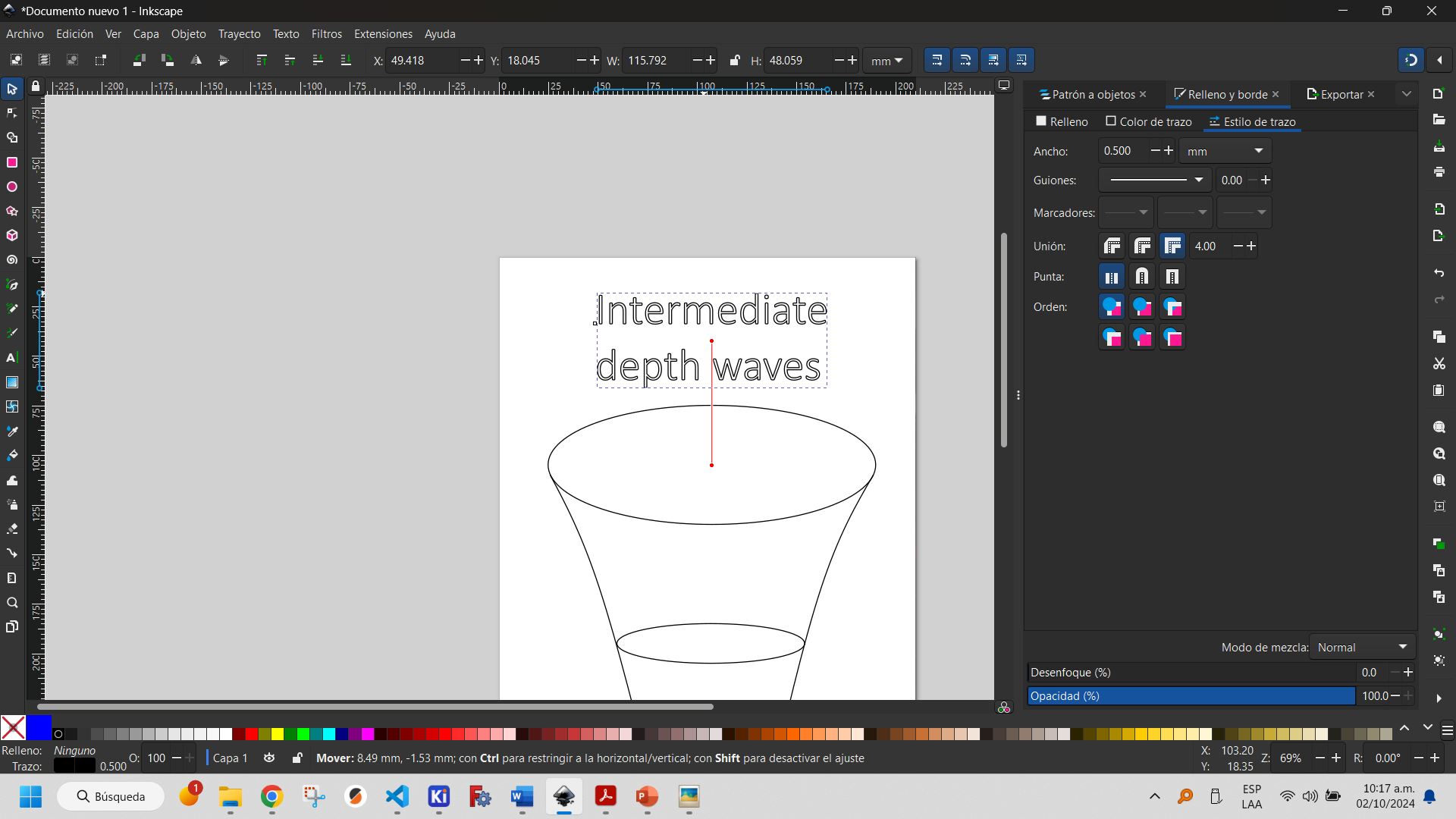
It is possible to fill the objects created to give them a better appearance or for design needs. In the fill and border window it is possible to select the parameters you want to change. In my case I only added fill to the text.
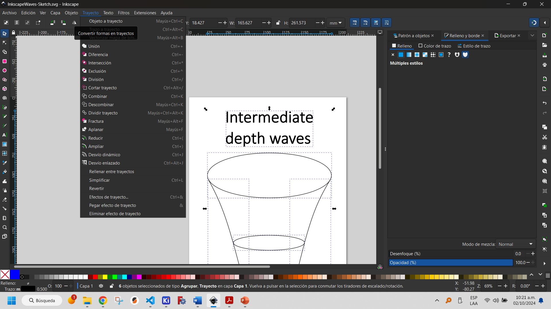
It is good practice to convert all objects that have been made into paths, in case these designs will later be used on a computer-controlled machine (CNC, Laser cutter, etc.). For this purpose, the object-to-path function is used.
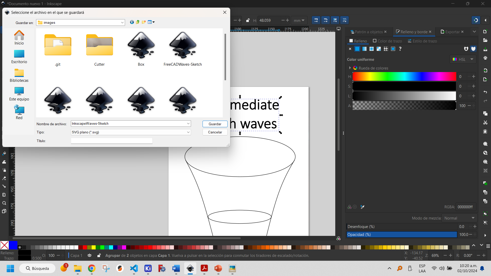
Saving files in Inkscape directly shows that they are saved as Inkscape SVG. Due to compatibility issues it is recommended that they are saved as plain SVG.
The final design can be viewed below.

Although Inkscape was created primarily to meet the needs of professionals who make use of graphic design, it could be seen that it is software that allows vector drawings focused on this branch of knowledge, even without having full knowledge of it. Although it is a powerful design program, it is not recommended for more engineering designs, where dimensions and other constraints typical of this field must be used. That is why we will see another program more suitable for this purpose.
More information about how to use Inkscape can be found here.
LibreCAD is an open-source 2D computer-aided design (CAD) software application for 2D design. It was developed from a fork of QCad Community Edition and is based on the Qt4 libraries, allowing it to be run identically on various platforms.
The program also has the same tools for object construction as FreeCAD's Sketcher Workbench and allows you to include dimensions and constraints. These are shown below.
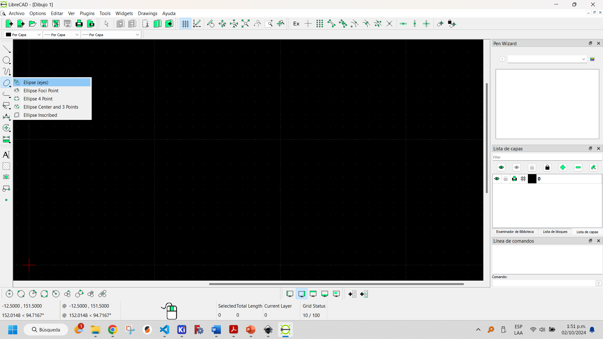
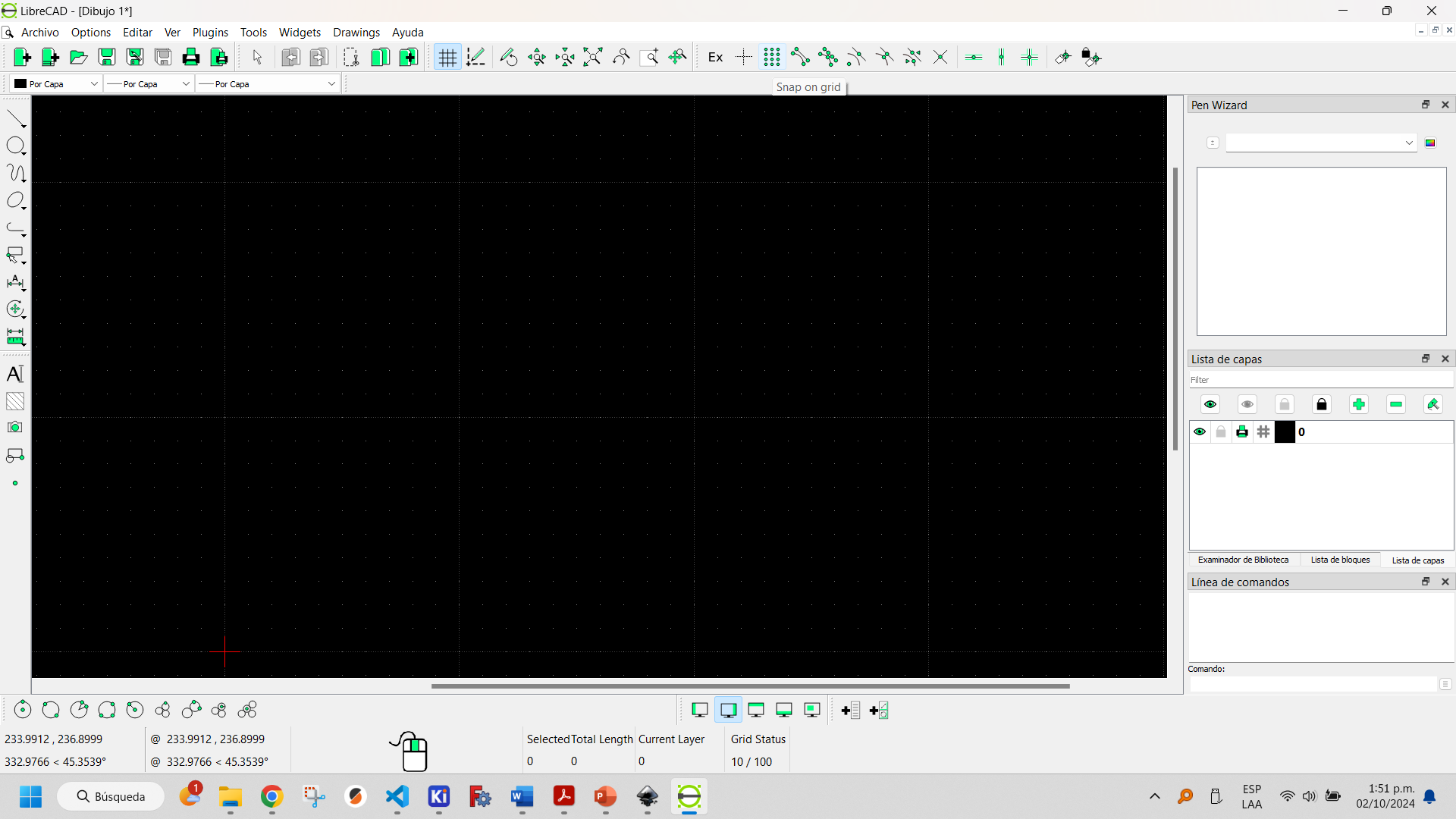
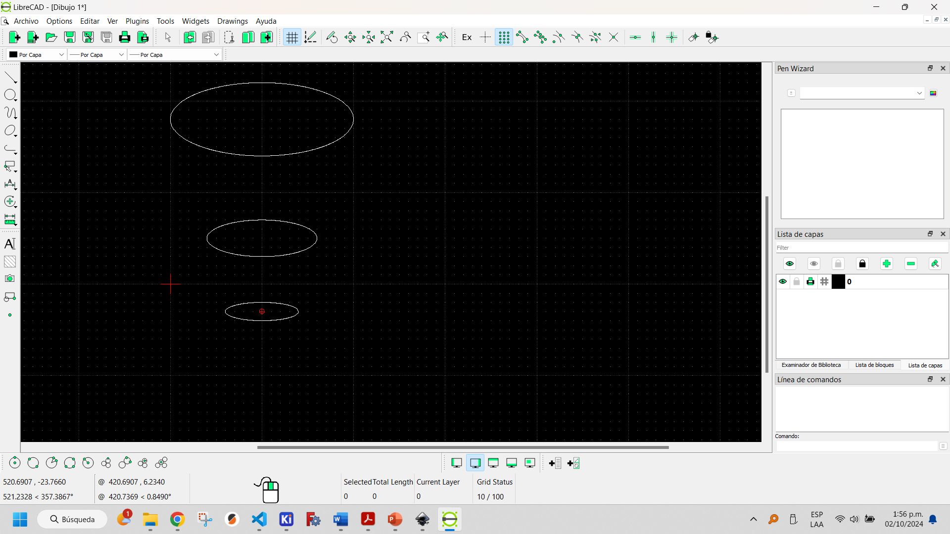
To create an ellipse, use the ellipse creation tool, which allows you to position it in the document and is very similar in design to FreeCAD's Sketcher Workbench.


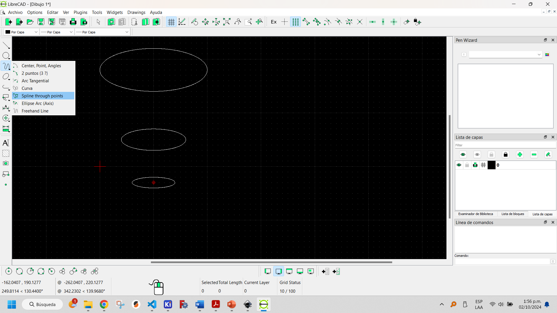
By using the freehand tool and selecting the B-spline plot type you can create curves with the desired shape.

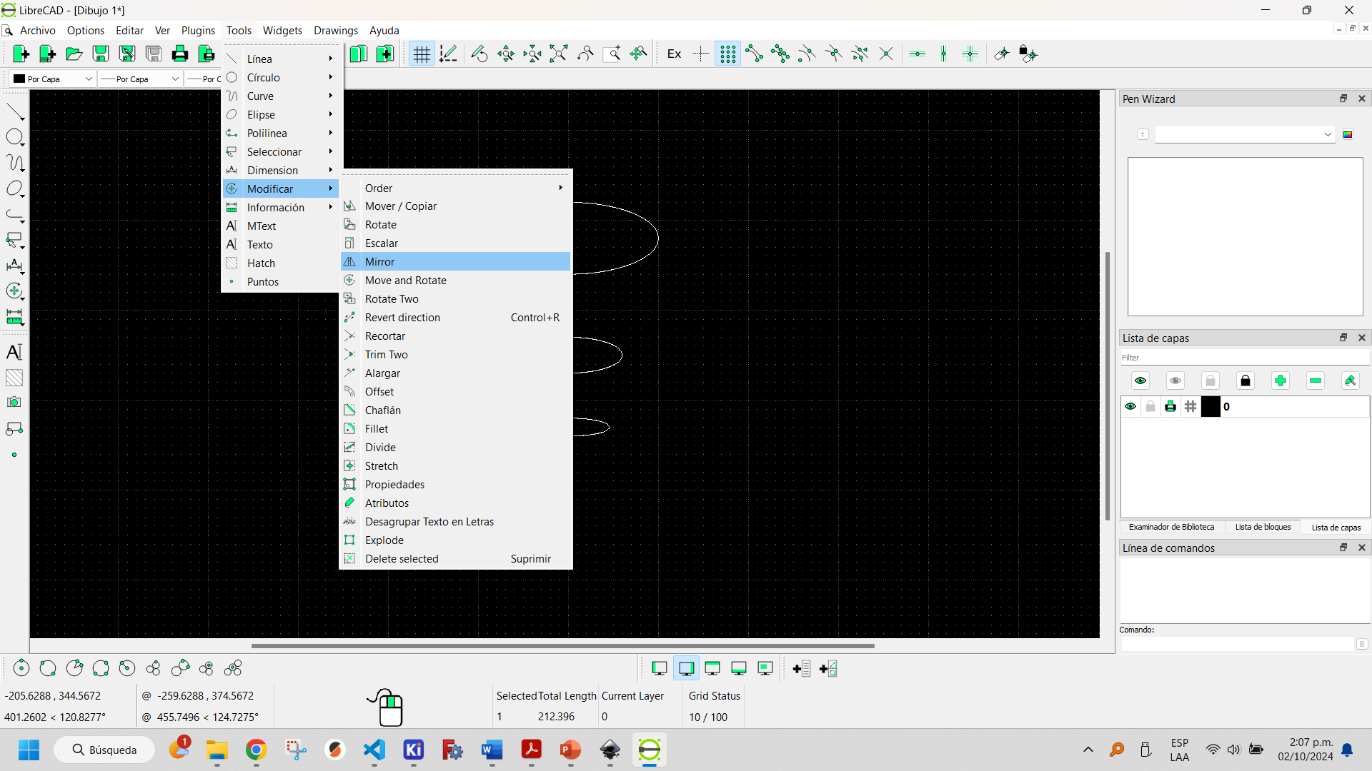
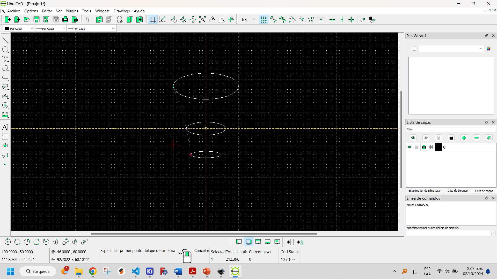
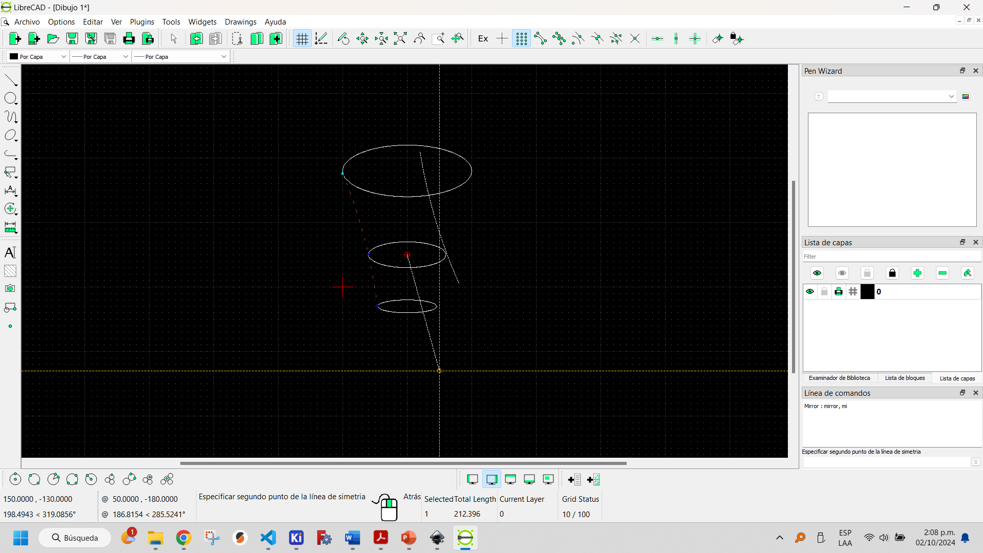
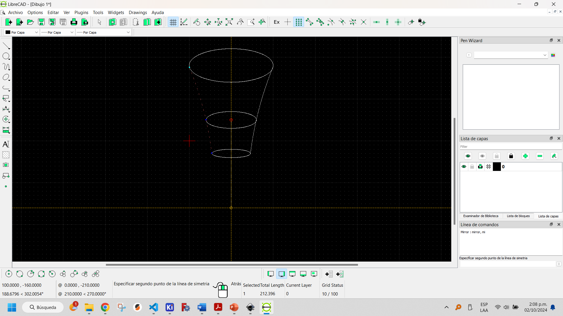
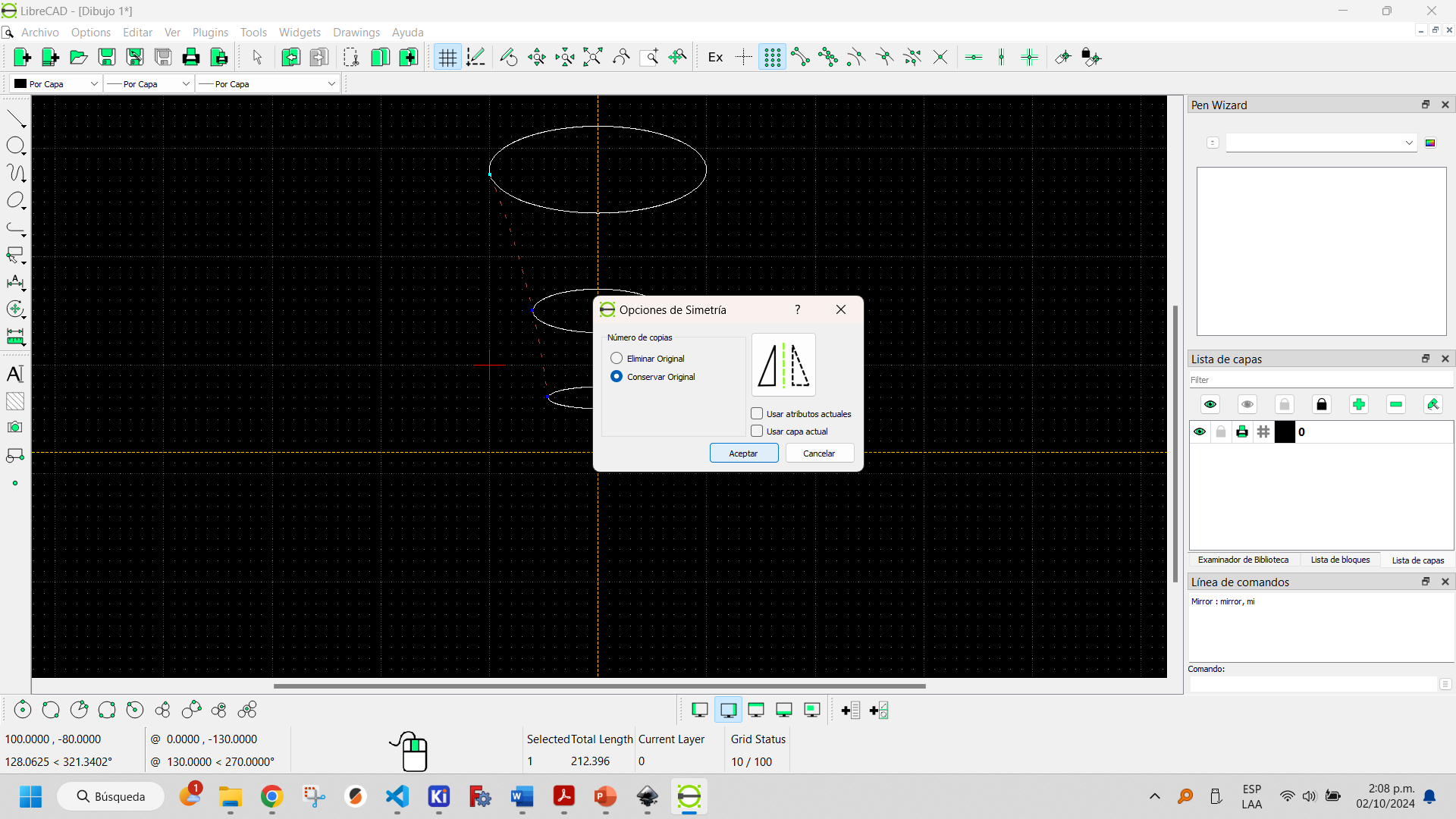
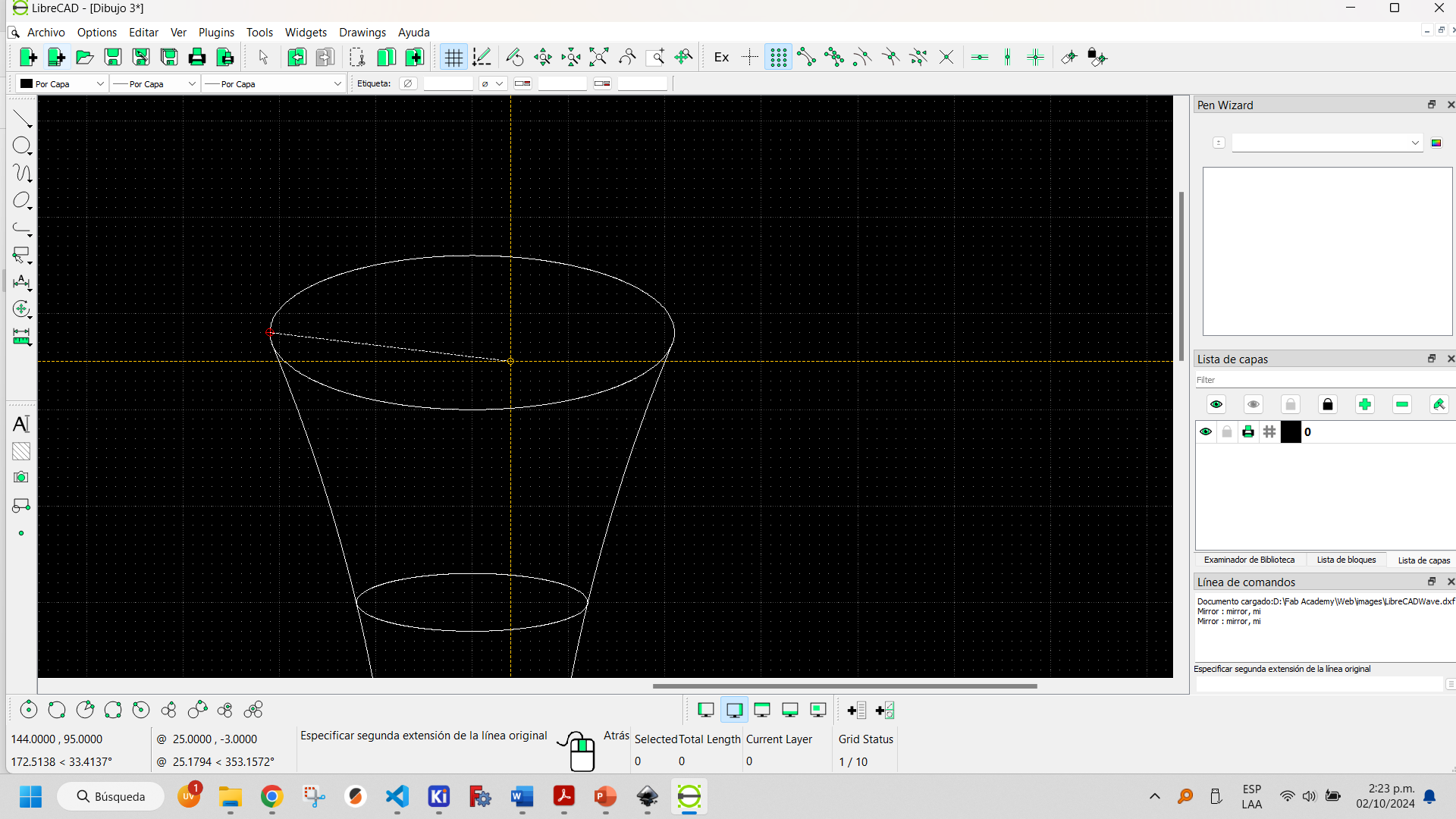
With the modify tab and using the mirror tool you can create a copy of the original object.
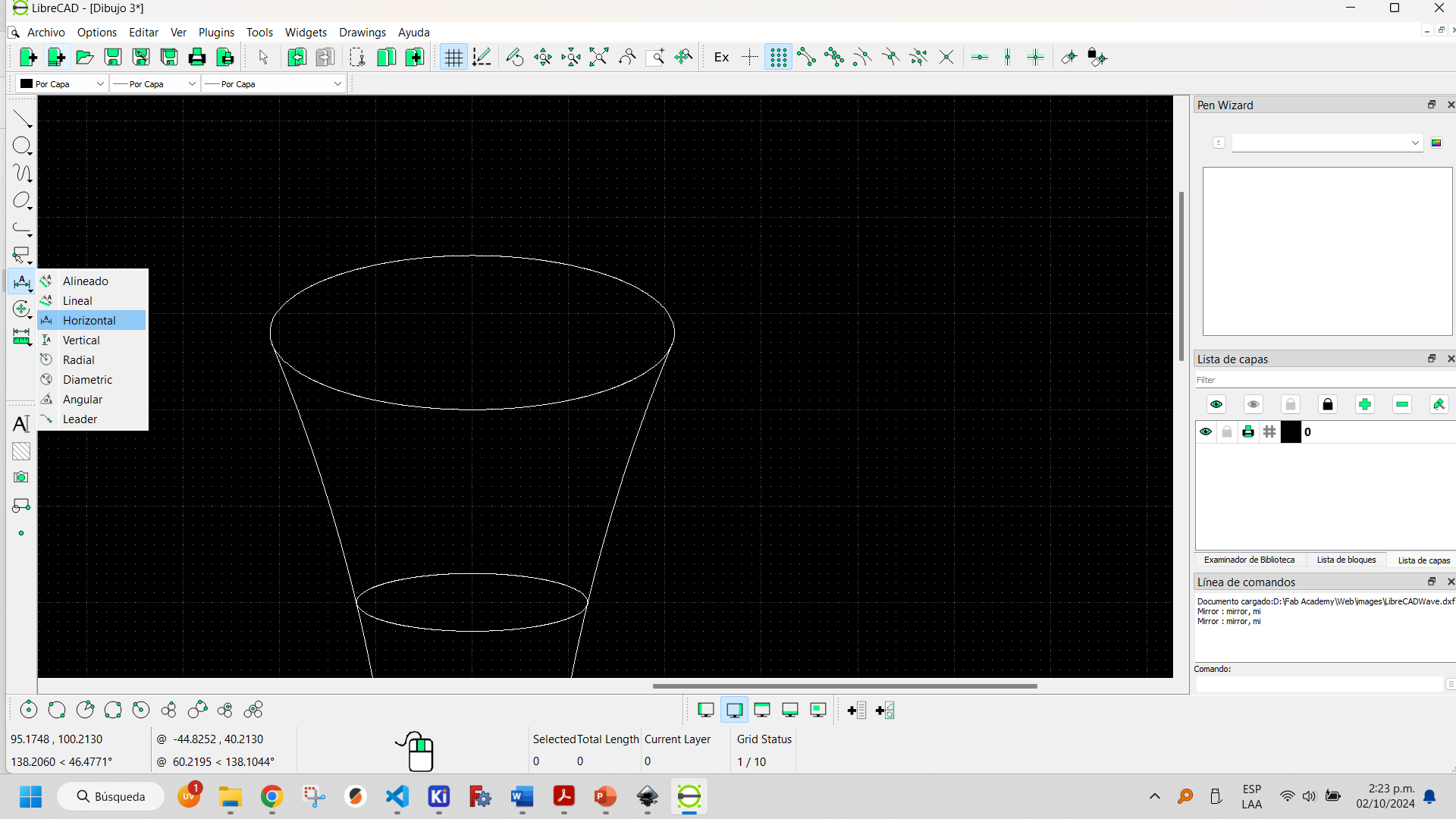
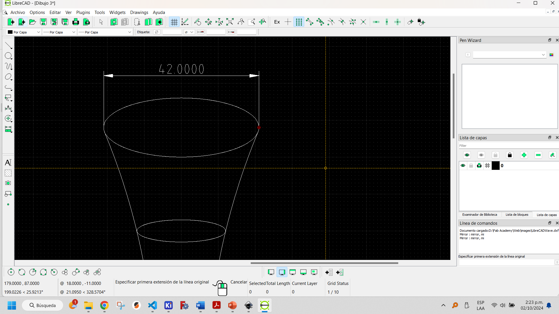
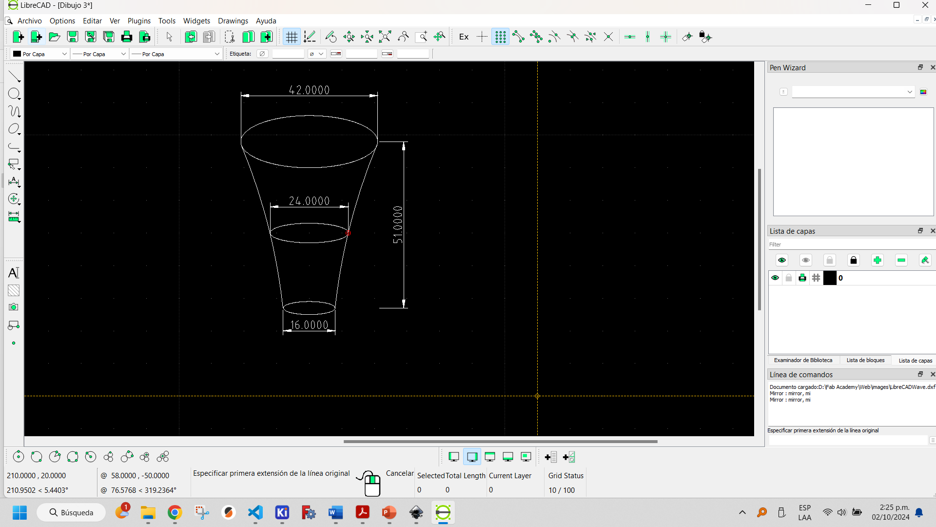
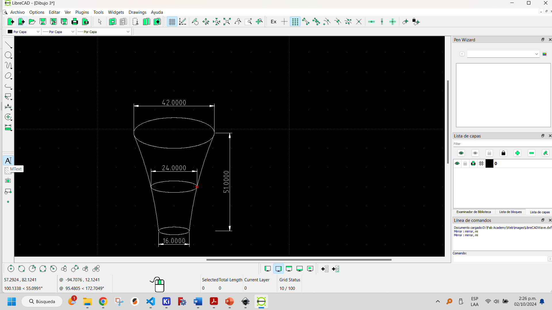
In the dimensions tab it is possible to add dimensions with different shapes and directions.
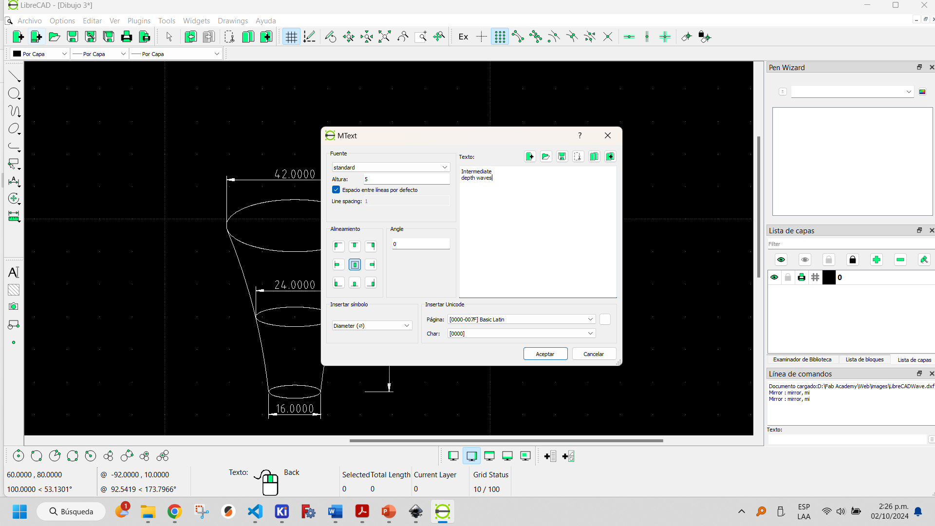
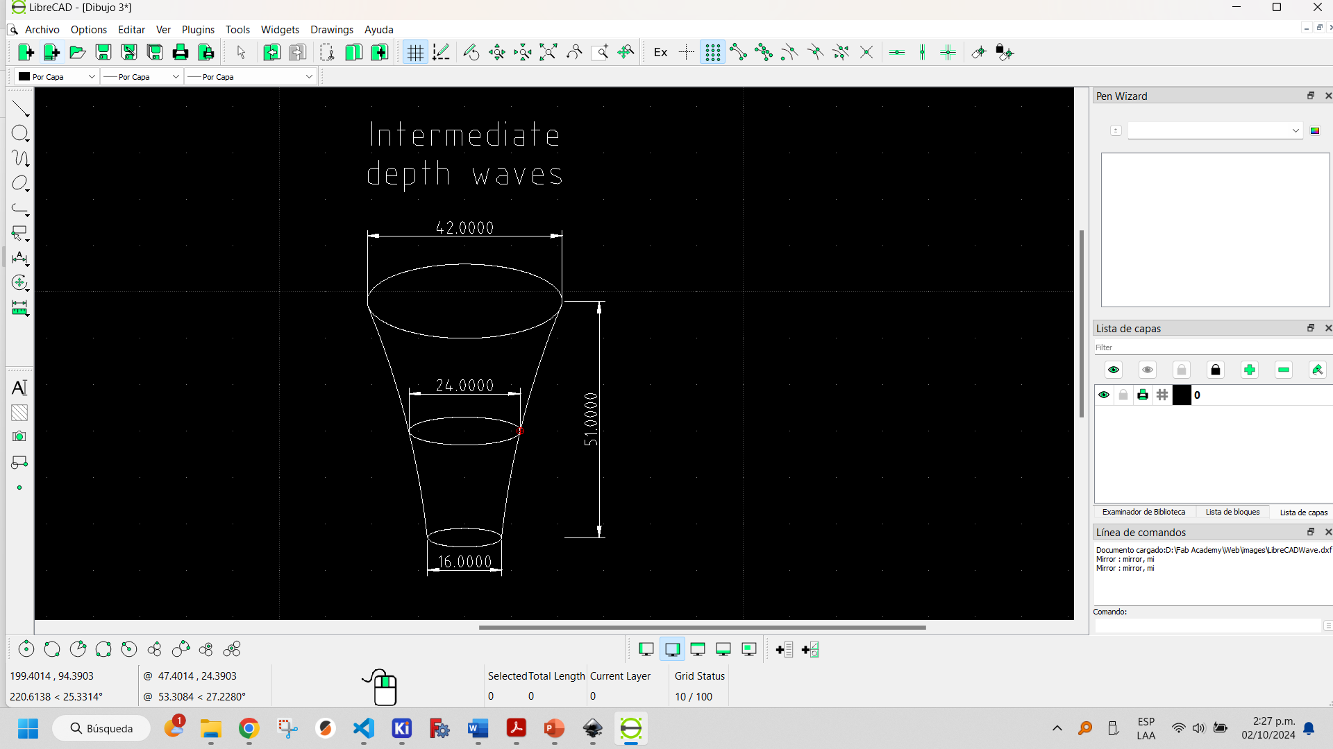
In the text tab it is possible to add text, but with a substantial difference to Inkscape: the text is made up of a single line, similar to the text that appears in technical drawings and datasheets.
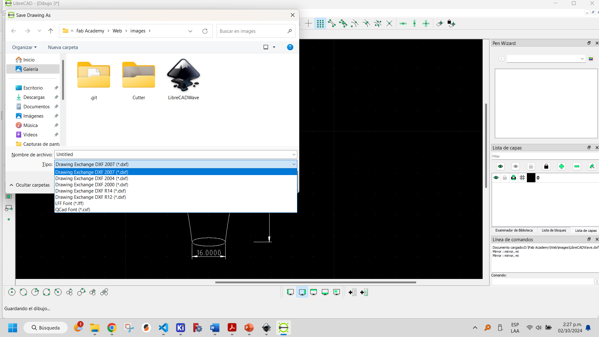
LibreCAD saves files in .dxf format.
We can conclude that FreeCAD's Sketcher Workbench is oriented to 2D drawings to serve as a basis for 3D designs, Inkscape is oriented to 2D artistic and graphic design, while LibreCAD is oriented to 2D drawings with an engineering and technical drawing cut.
More information about how to use LibreCAD can be found here.
You can download the LibreCAD file here.