
Welcome to Week 9
Output Devices
Hey! now we will learn about Output Devices,for this week we have the following group and individual assignments:
- Group assignment:
- Individual assignment:
o Measure the power consumption of an output device. - ✅ Done
o Document your work on the group work page and reflect on your individual page what you learned. - ✅ Done
o Add an output device to a microcontroller board you've designed and program it to do something. - ✅ Done
GROUP ASSIGNMENT
Output devices are components that enable a system to interact with the external environment. Examples include engines, screens, LEDs, and more.
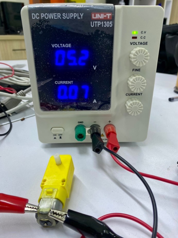
First of all, as a group work, we will use test equipment to measure the voltage and consumption of the electronic component that we will use for this part. This component is a dc power supply UTP1305 of the brand "UNI-T" and you can get it here .

Power is determined by multiplying the voltage across a component by the current passing through it:
P = I * V
I used this formula to calculate the power flowing through a small DC electric motor, I connect the motor to a source, in the image we can see that the voltage is: 4.8 Volts, and the current is 0.02A.
In order to have a more exact measurement of how much voltage was reaching the motor, I placed my multimeter and it read a voltage of 5.24v.
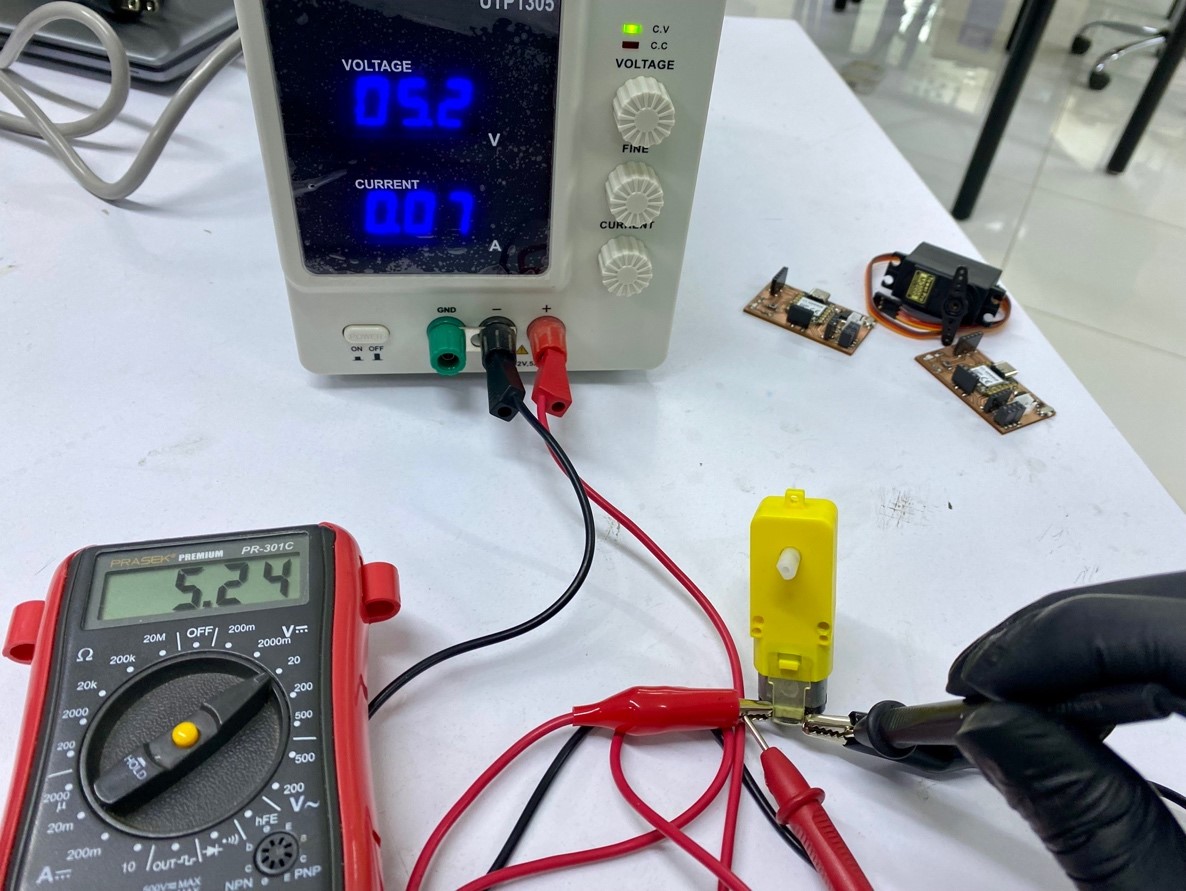
Now let's do tests with free movement and placing resistance on the motor.
In the video, I = 0.07 is observed when the motor rotates freely and a maximum measurement of I = 0.16 when the motor shaft was prevented from moving.
Thus, we can calculate the power of the motor that consumes 5.24 x 0.07 = 0.37 watts in free movement and 0.83 watts with resistance of movement.
Ready! We learned about the power consumption of output devices……
INDIVIDUAL ASSIGNMENT
It is time to experiment a little with these devices and the development board, for which we will do two experiments with the output devices that I will show you in the following image.
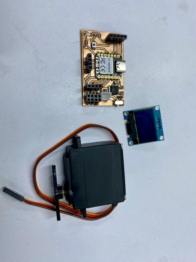
Let's hit it! first let's start with the servomotor….

We upload a programming so you can make progressive turnles.
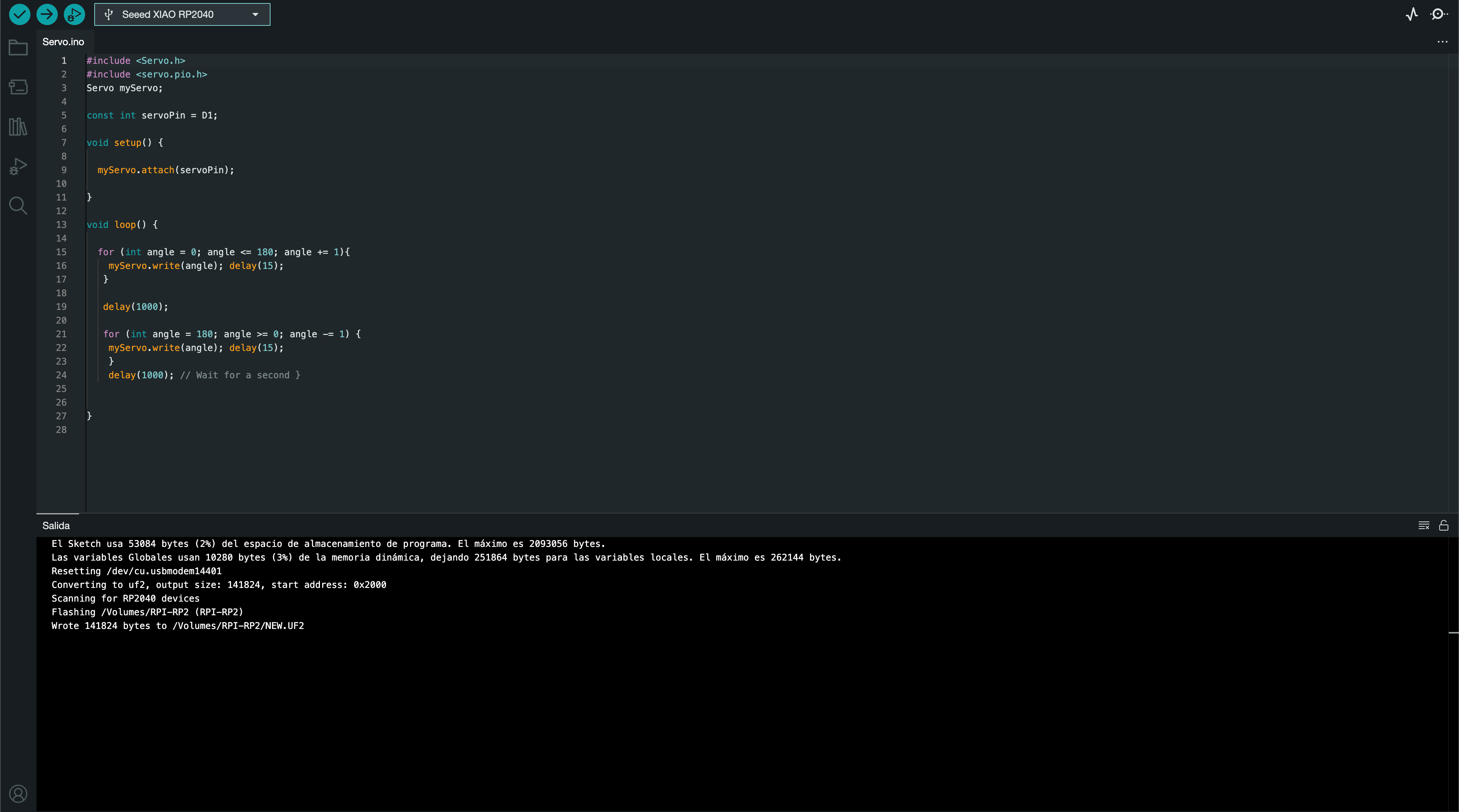
The code is one of test for servomotors that is within the examples and tests of arduino but I still leave them here. And you can get the librarys for this code here.
      1 #include <Servo.h>
      2 #include <Servo.pio.h>
      3 Servo myServo;
      4
      5 const int servoPin = D1;
      6
      7 void setup(){
      8   myServo.attach(servoPin);
      9 }
      10
      11 void loop(){
      12   for (int angle = 0; angle <= 180; angle += 1){
      13     myServo.write(angle);
      14     delay(15);
      15   }
      16
      17   delay(1000);
      18
      19   for (int angle = 180; angle >= 0; angle -= 1){
      20     myServo.write(angle);
      21     delay(15);
      22   }
      23   delay(1000);
      24 }
Let's see how this program works…
Ok, now we continue with the OLED..
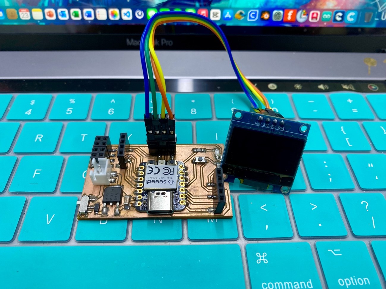
We upload a program so that it shows us a phrase on the OLED
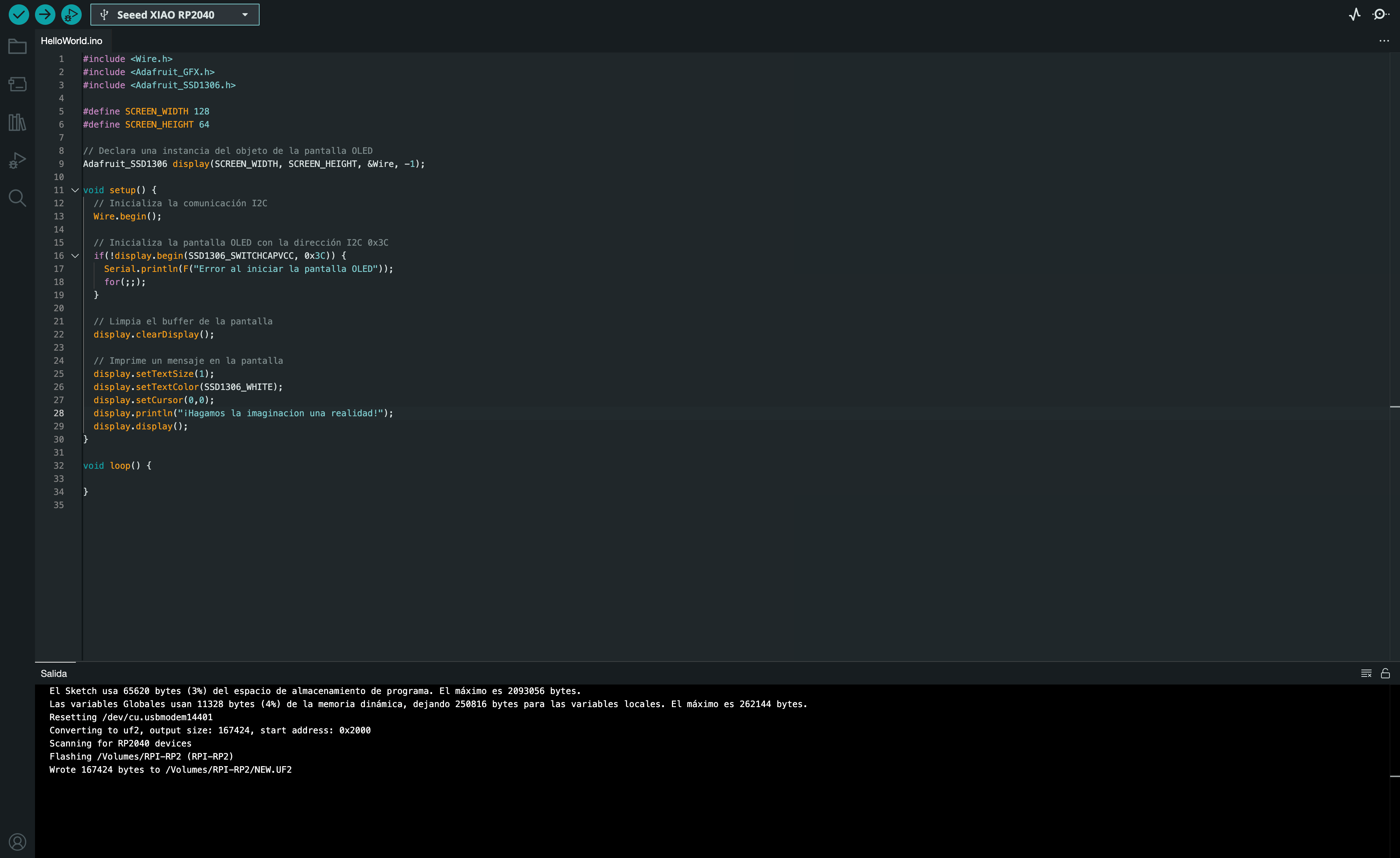
The code is a test for OLED screens of own elaboration I leave the code here so that they can copy it. The libraries for this project can be found here and here.
      1 #include <Wire.h>
      2 #include <Adafruit_GFX.h>
      3 #include <Adafruit_SSD1306.h>
      4 #define SCREEN_WIDTH 128
      5 define SCREEN_HEIGHT 64
      6
      7 Adafruit_SSD1306 display (SCREEN_WIDTH, SCREEN_HEIGHT, &Wire, -1);
      8
      9 void setup() {
      10   Wire.begin();
      11   if(!display.begin(SSD1306_SWITCHCAPVCC, 0x3C)) {
      12     Serial.println(F("Error al iniciar la pantalla OLED"));
      13   }
      14   for(;;);
      15
      16   display.clearDisplay();
      17   display.setTextSize(1);
      18   display.setTextColor(SSD1306_WHITE);
      19   display.setCursor(0,0);
      20   display.println("¡Hagamos la imaginacion una realidad!");
      21   display.display();
      22 }
Let's see how this program works…
Learning
Well we finished the assignment and we definitely did not take away important learnings:
o Power consumption becomes greater when the actuator is under some pressure or resistance.
o There are libraries which can facilitate the programming of output devices, however not all libraries will be compatible with the XIAO RP2040.
Ready! That was all for today's task, here I leave the files so you can experiment, see you next week with something crazy that comes to mind