
Welcome to Week 7
Computer Controlled Machining
Hello! this time, let’s learn about Computer Controlled Machining, for this week we have the following group and individual assignments:
- Group assignment:
- Individual assignment:
o Complete your lab's safety training - ✅ Done
o Test runout, alignment, fixturing, speeds, feeds, materials and toolpaths for your machine - ✅ Done
o Document your work to the group work page and reflect on your individual page what you learned - ✅ Done
o Make (design+mill+assemble) something big - ✅ Done
GROUP ASSIGNMENT
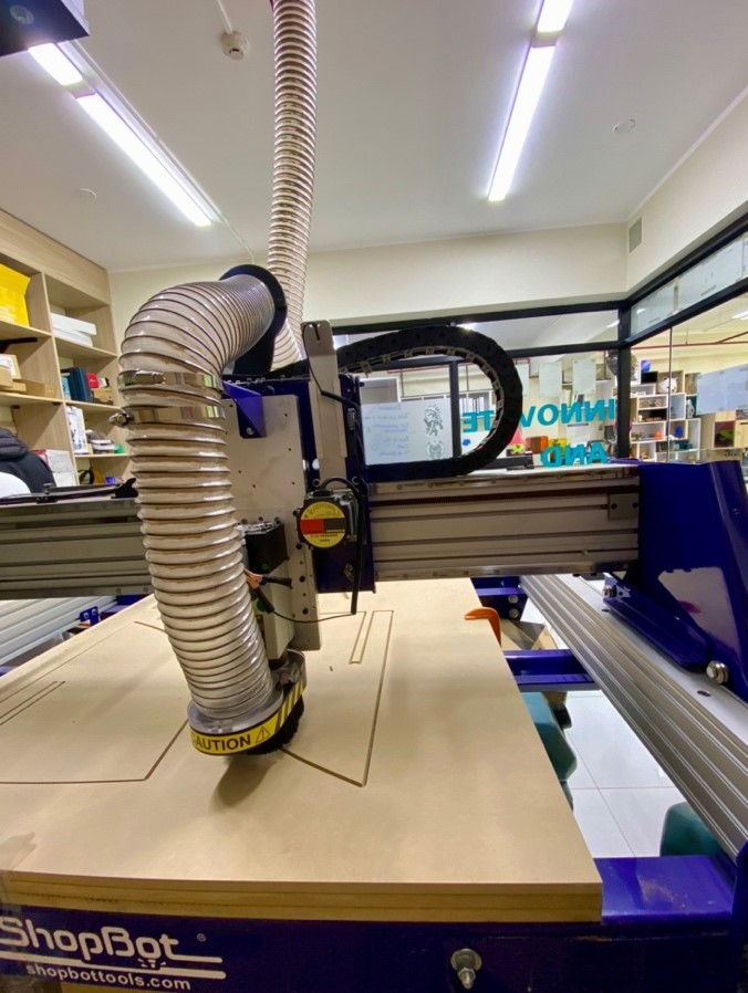
The machine we have at Continental University is the SHOPBOT PR ALPHA MODEL 120 – 60 that we will use for this week's work. Below are some specifications of the machine:
This is the supplier: ShopBot
| CUT / MOVEMENT AREA: | 129” x 61” x 8”s |
|---|---|
| XY POSITIONING SPEED: | Variable, max. 1800”/min. |
| Z POSITIONING SPEED: | Variable, max. 900”/min. |
| LINEAR CUTTING FORCE: | Approximately 150 lbs. |
| INPUT VOLTAGE: | 220v single-phase, 230v 3-phase and 380/460V 3-phase power options are available |
The material is not glued, but rather held in place by presses that keep the material immobile while the machine is running.
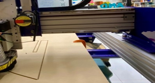
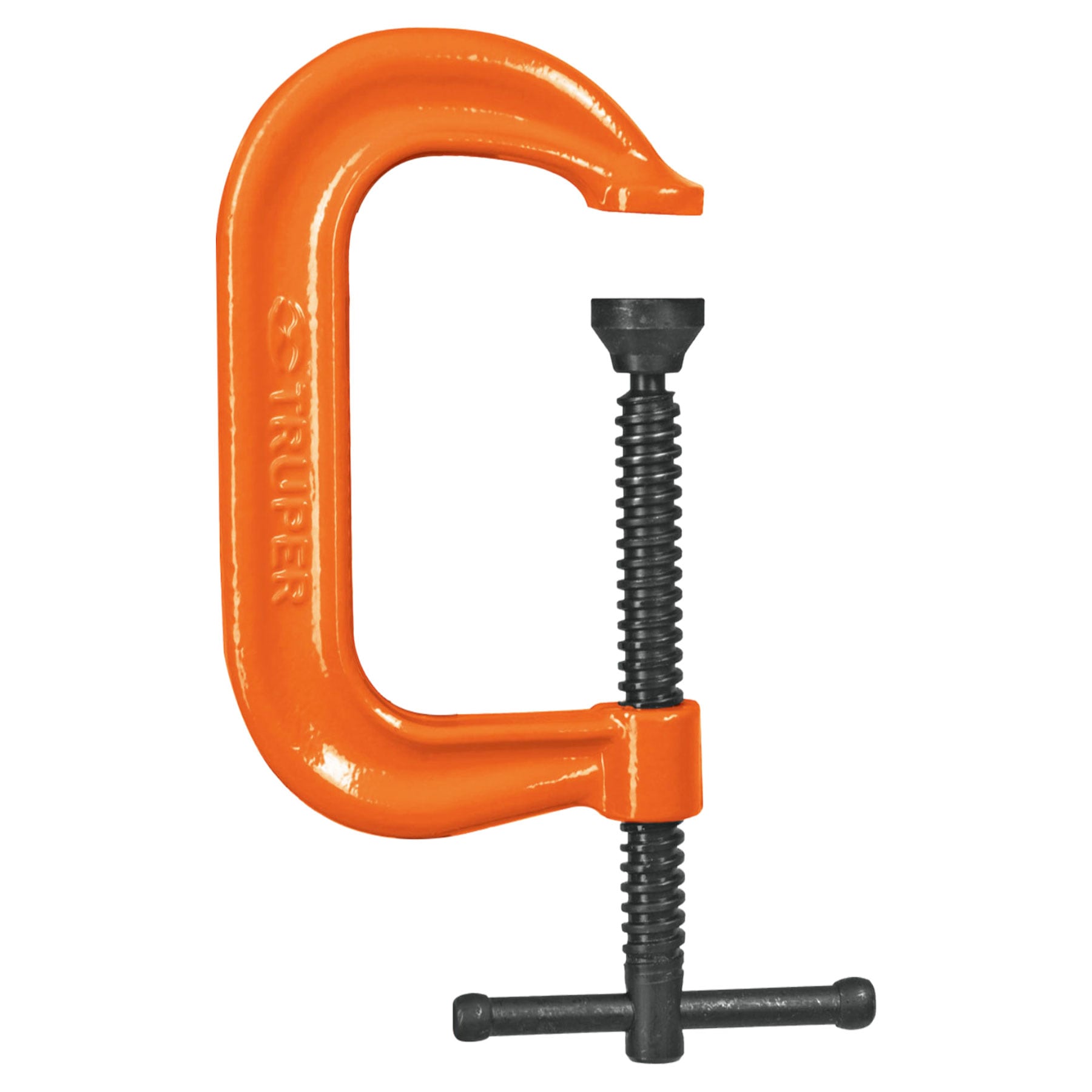
We use C-shaped presses for greater grip and strength when clamping the material.
Within the specifications you can see the feed rates and speeds of the mill being used. Here is the link: Feed rate and speed parameters
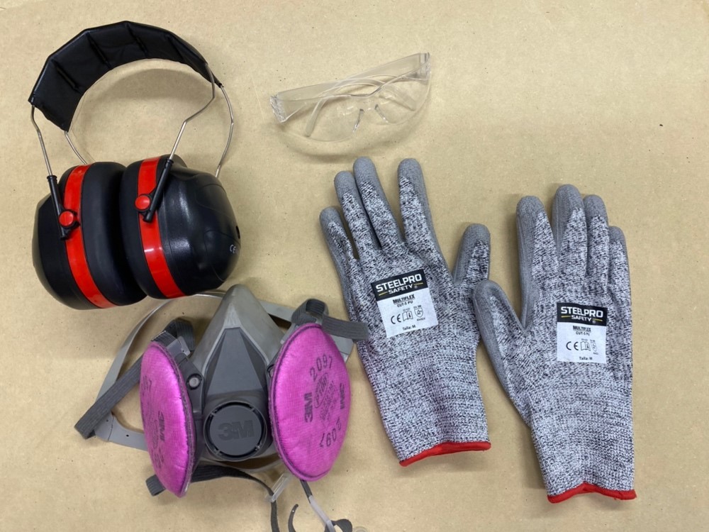
We prepare our security team to be able to comply with security aspects and be able to start working.
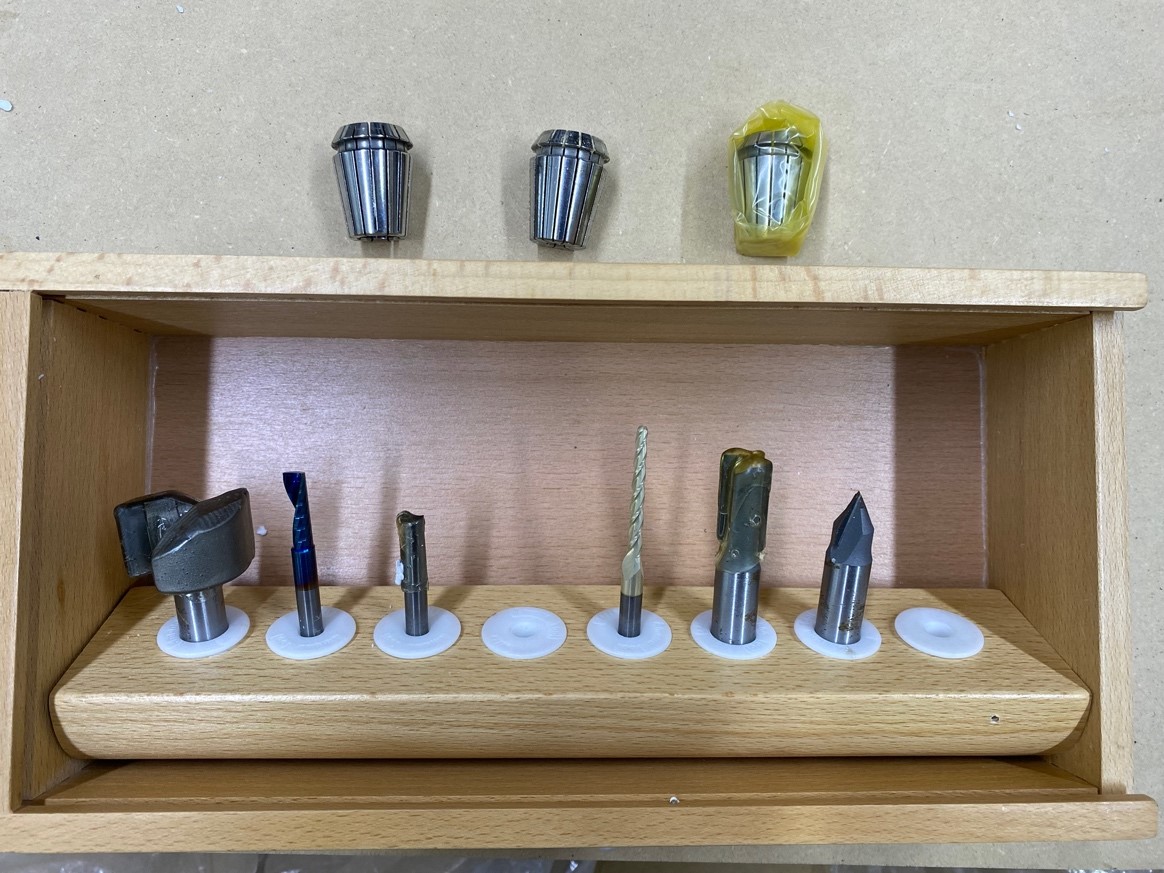
The implements we have for the CNC machine are 1/4", 1/8" and 5/8" cutters along with their ER25 collets and a cutter that comes with the SHOPBOT. For our group and individual work we will use the 1/4".
Well now let's open the Vcarve pro program and make some initial configurations such as the calibration in x, y as well as the calibration in z.
When you open the program, 2 windows will appear. The POSITION is where we perform the calibration, movement and start or stop control of the machine. The second window is COMMAND CONSOLE where we can open the trajectories, warm up the machine and, if it is the first time we use it, its configuration.
To calibrate the Z axis, we have to click on the Z button in the Position window. Before calibrating, we have to place the hook on the SPLINDER and the metal plate on the material, so that the machine can be calibrated.
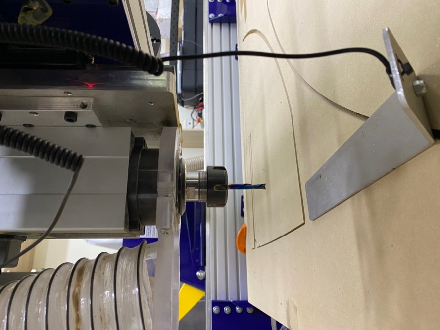
From this point onward, the machine will exclusively focus on calibrating its Z-axis before initiating its operations. Below is a video demonstrating the calibration process in action.
Now yes! let's do some tests to find the tolerances just like we did with the laser cutting.
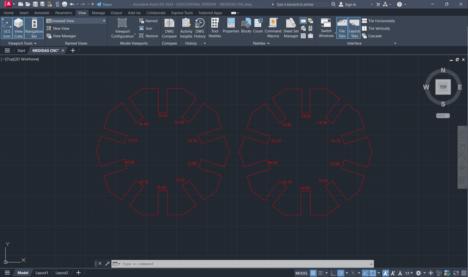
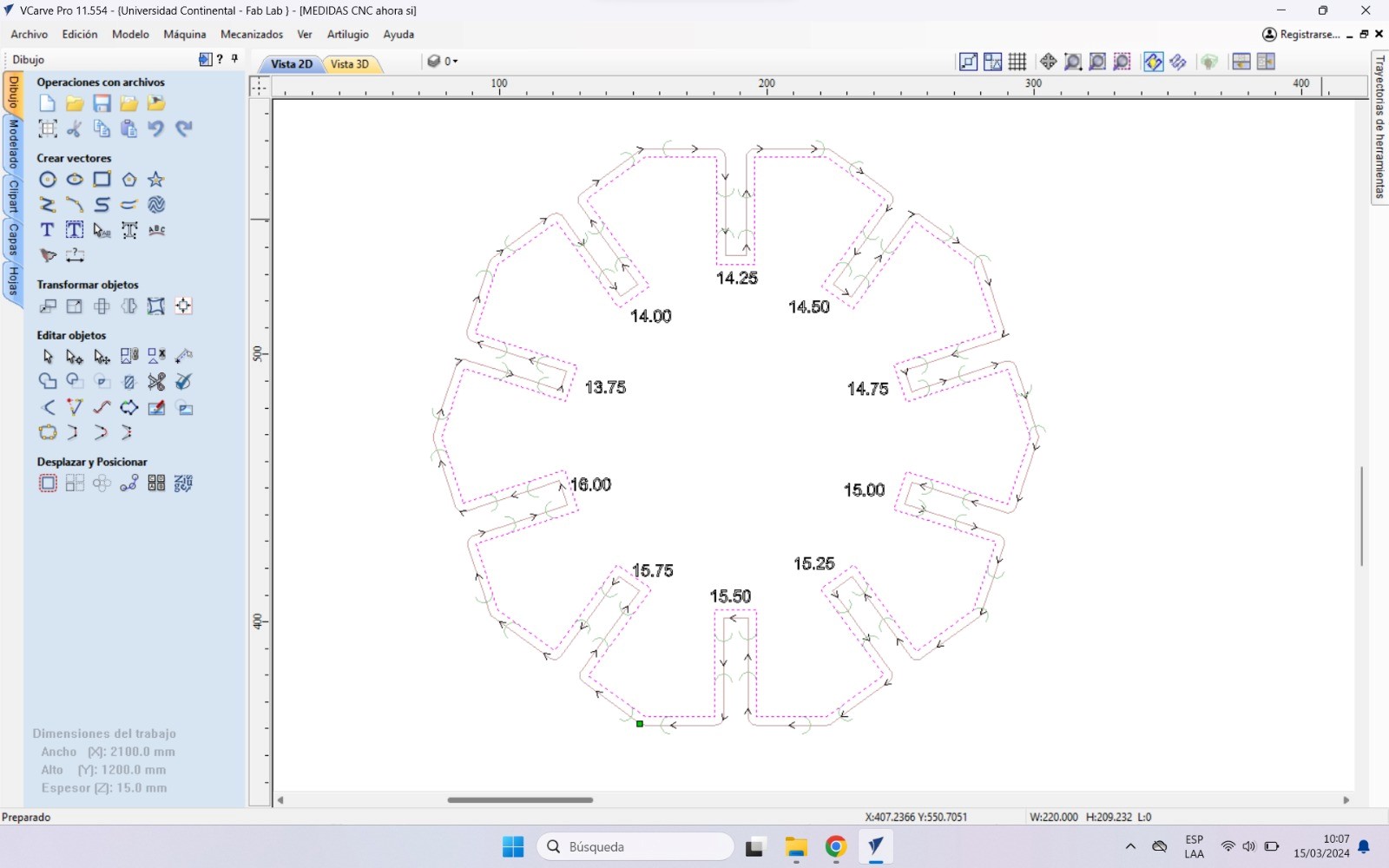
The initial test we conduct is the HEX COMB, aimed at identifying the optimal fit. Throughout all our tests, we'll utilize 15mm PLYWOOD, consistent with the material we'll employ in our individual project.
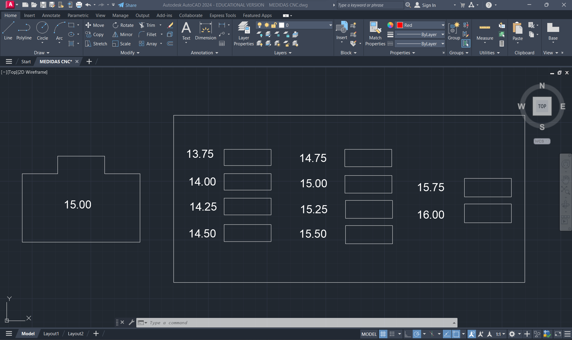
First, what we did was make the drawing in AUTOCAD taking into account the thickness of the material, which is 15 mm, and we gave each section a value of +0.25 mm to see which measurement was appropriate for a correct fit.
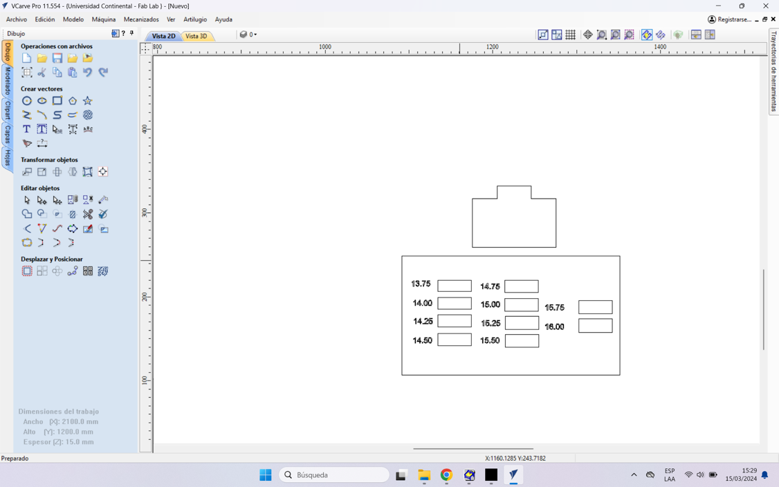
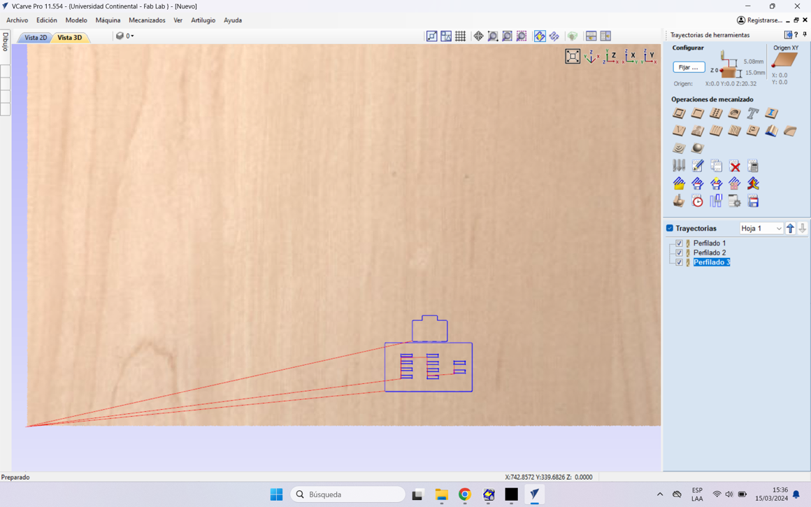
Now with the design we proceed to transfer it to the Vcarve Pro and cut it.
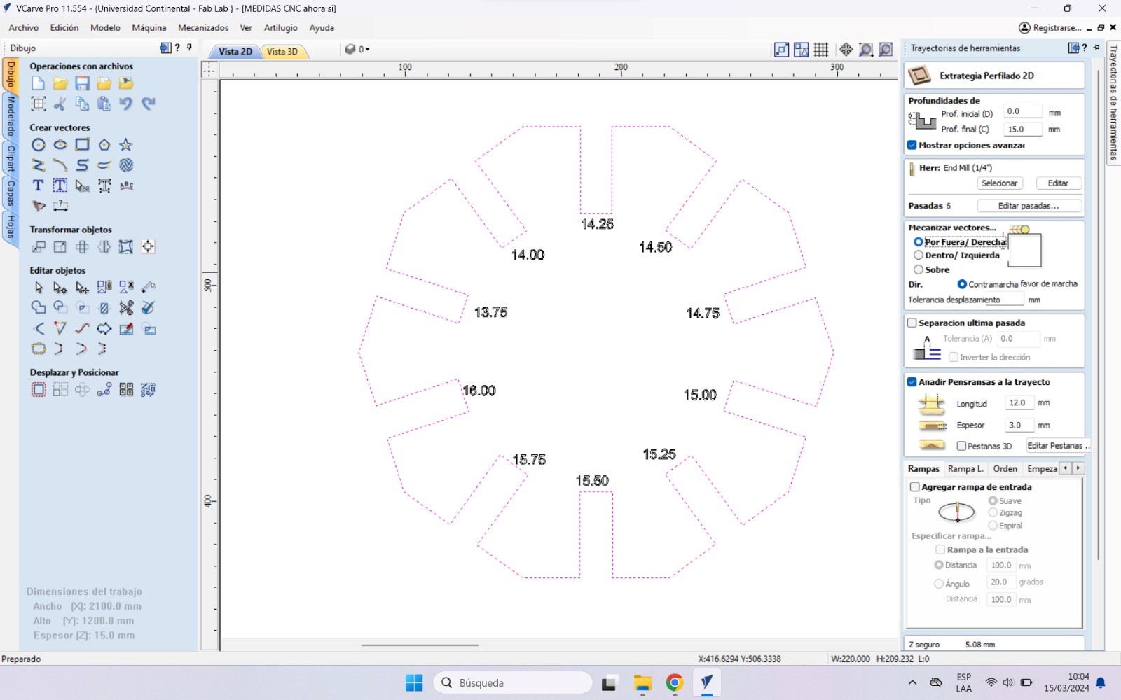
Select the part and then put in the tab "Tool path", in there it depends if the cuts will be inside or outside, we must select. In this case it is on the outside so we select that option.
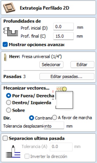
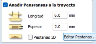
To ensure that the part is held steady while cutting, we add "Tabs" to secure the part.
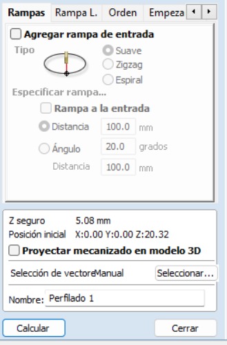
And finally we click on the calculate button, and the piece with the calculated trajectory will be ready to pass it to the shopbot.
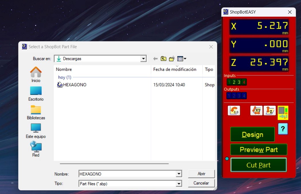
We open the shopbot program and proceed to upload the file to spawn
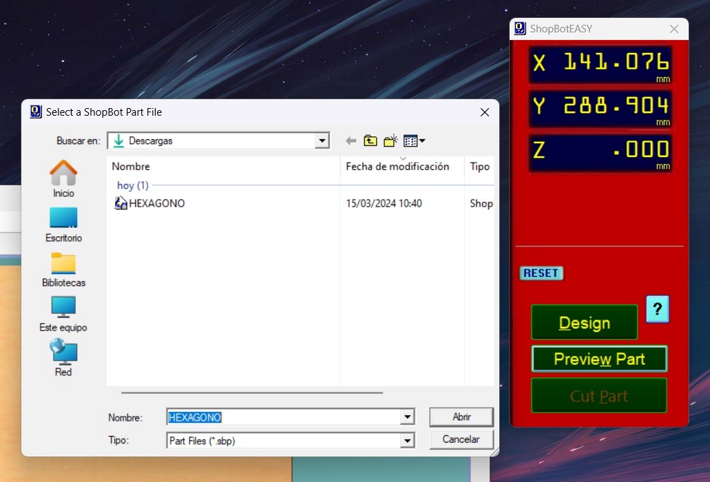
Push open and start, let's see the process :
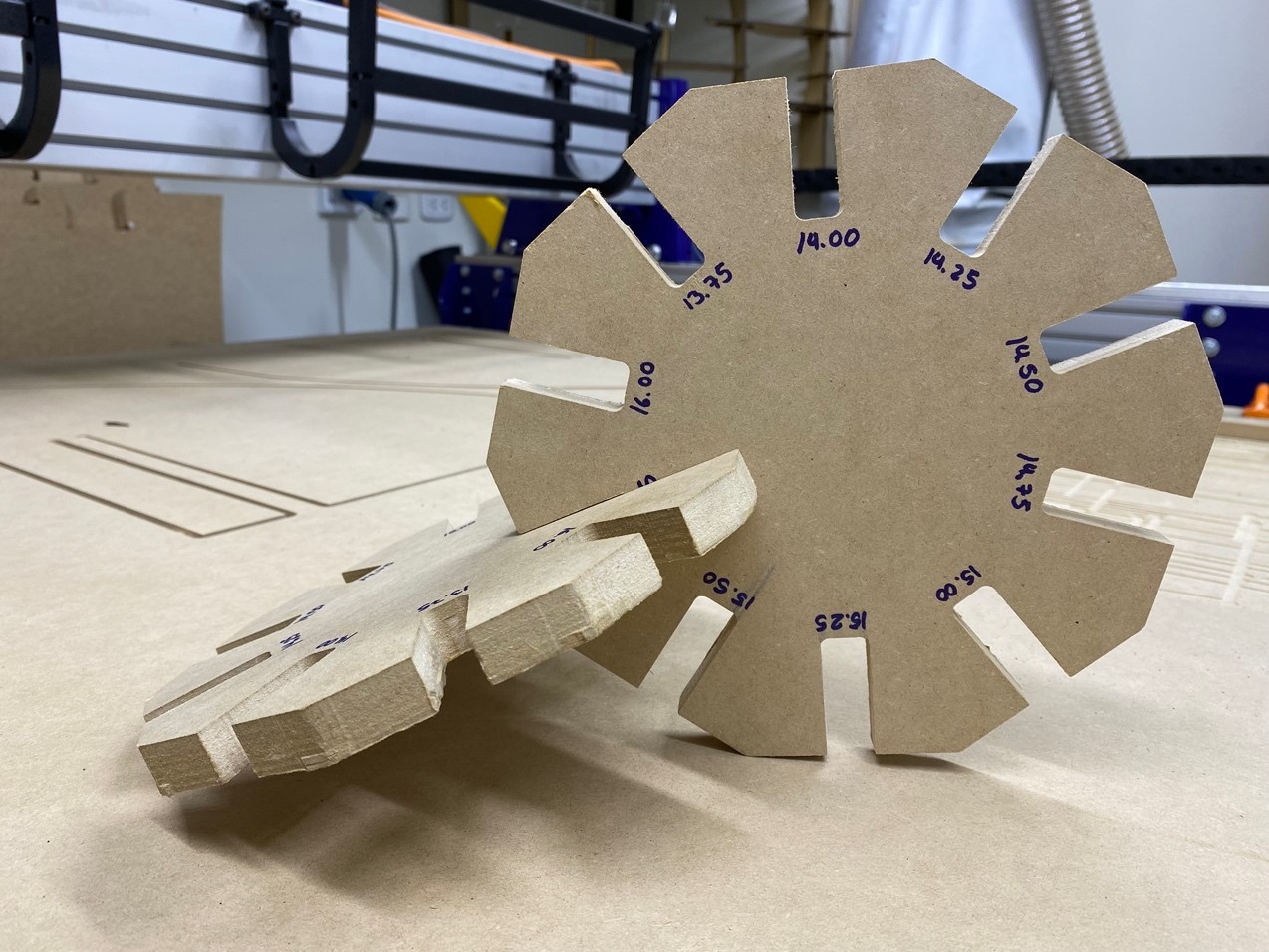
After cutting both hex comb, we can analyze and verify that the best joint for joints that are like this is for the cuts to have +0.75mm of the thickness of the material. In this case, for the 15 mm material the ideal cut would be 15.75 mm for a better fit of the pieces
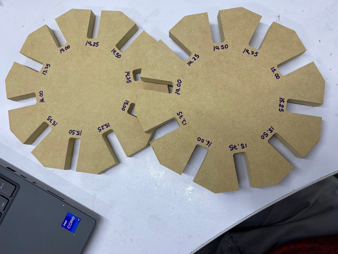
It looked great, let's move on to the next test…
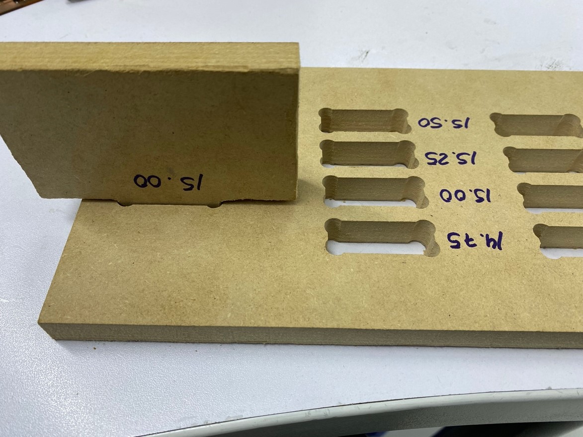
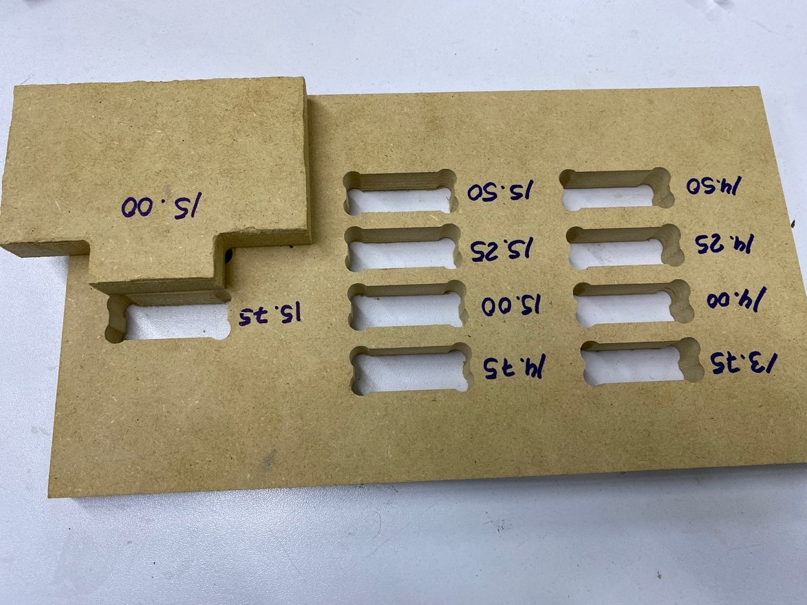
The subsequent test involves the evaluation of the dog bone and hole configurations. The objective of this test is to determine the optimal sizes required for the pieces to fit precisely within the holes. The dog bone test facilitates easy insertion of the pieces while ensuring that corners pose no issues, particularly with the female pieces. Conversely, the hole test helps determine the appropriate size for the female piece to accommodate the male piece smoothly without causing damage to the material.
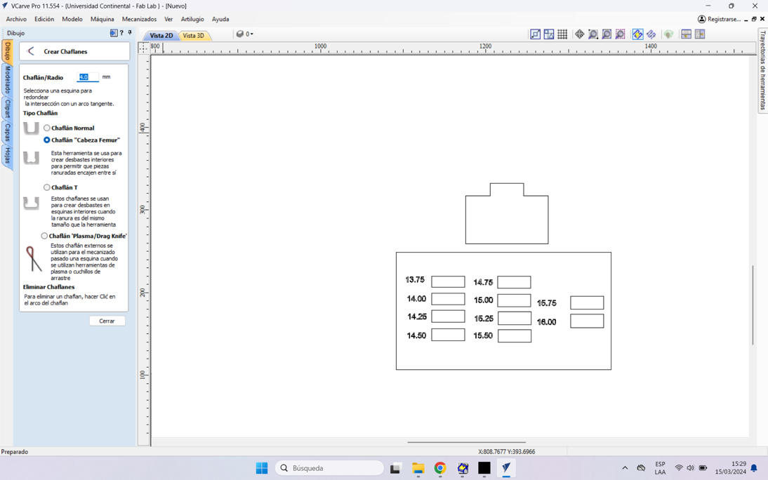
To shape the dog bone, we can utilize VCarve Pro after designing the pieces. Upon importing the design, we navigate to the "Create Chanfle" button to implement the necessary shaping.
Now we give you the cutting path to start with the crop.
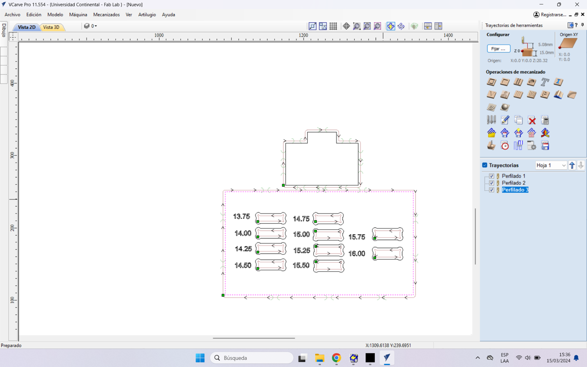
Let's see the process
We can see that the MALE piece easily fits into the +0.40mm hole, that is, if the piece has a thickness of 15 mm, we need the female piece to have a hole of +0.75mm, in this case 15.75mm.
This will help us with the lace that we will give to the rhinoceros pieces. More than anything in the laces that are cut internally in some pieces.
INDIVIDUAL ASSIGNMENT
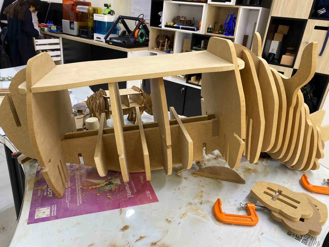
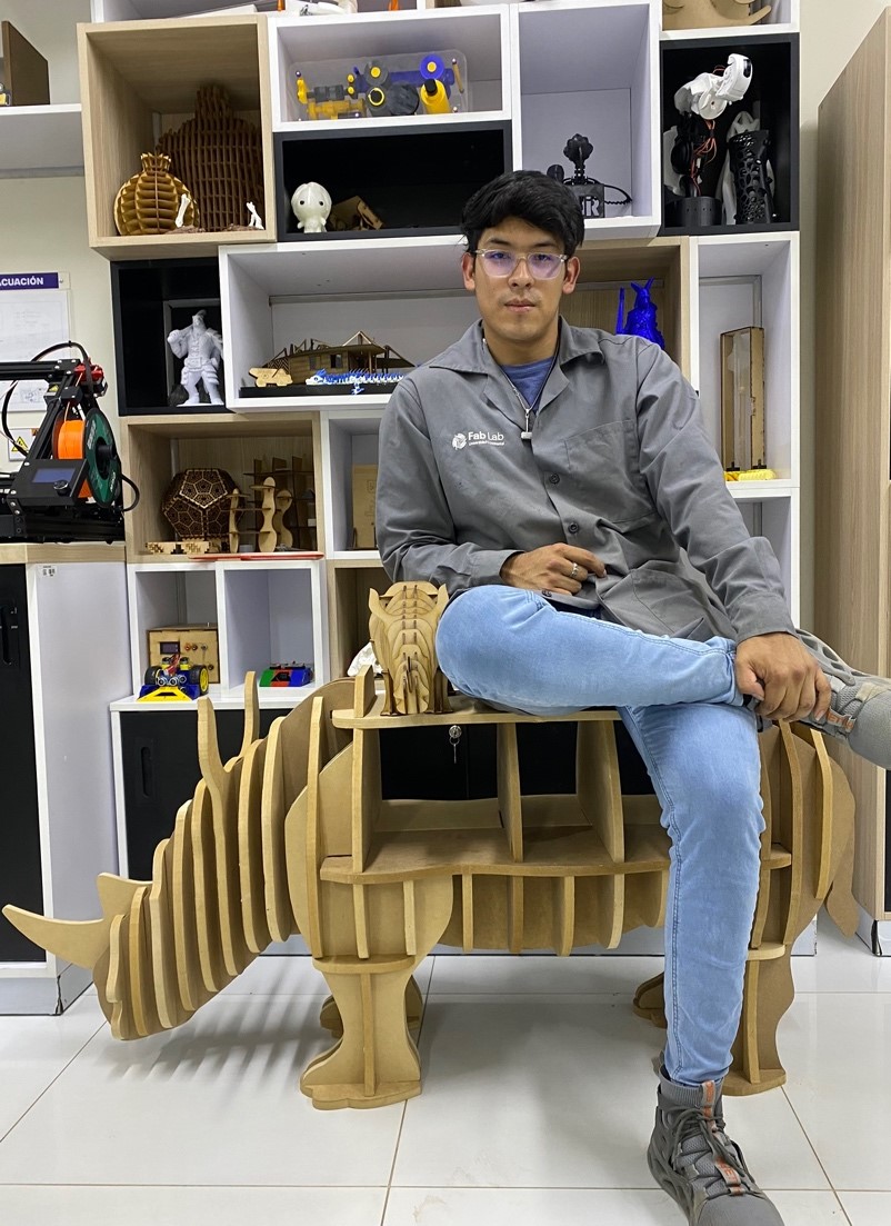
Ready now let's put together something big and cool, i decided to make a piece of furniture where they can sit but that also has additional functionality to hold some things like tools or books at the bottom. An animal came to mind which is quite robust, a rhinoceros.
This is the rhinoceros that will guide us to make our own:
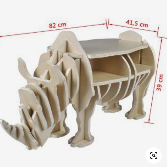
The picture does not show the drawings. This rhinoceros model caught my attention so much that I decided to investigate how to make the joints of the pieces. With my knowledge in architecture and design, I was able to develop the plans in the desired scale. These plans are shown below.
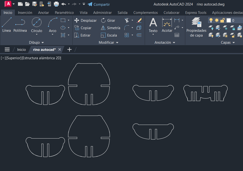
Let's start the design in AutoCad.
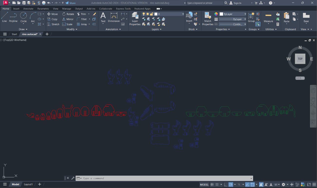
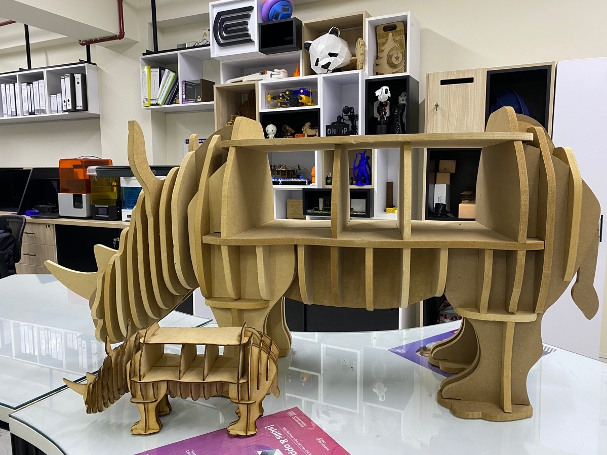
I've chosen to create a small-scale model of my selected proposal using 3mm MDF. This material was selected based on our previous work in the 3rd week to analyze potential stability issues and assess whether any design improvements are necessary.
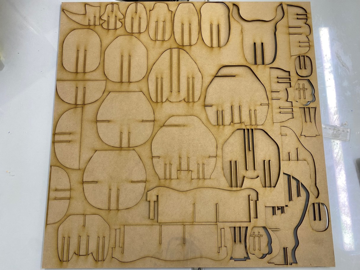
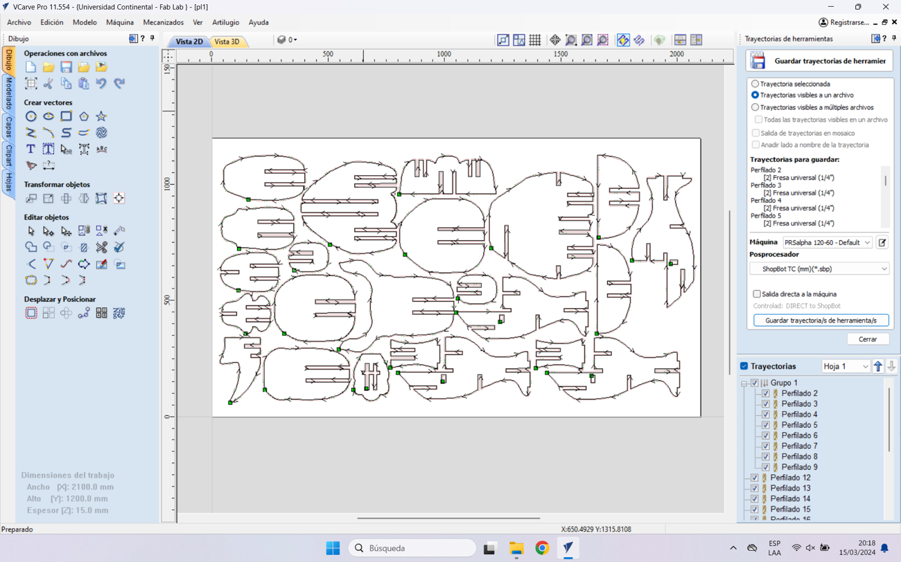
After analyzing and correcting the errors obtained in the model, I decided to start machining the parts, also importing into VCARVE PRO, I started selecting the female holes of the parts, by the way I changed the size of the holes with the appropriate measurements mentioned in the tests.
After analyzing the test model we identify the parts that need to be processed with “Dogbones” and modify them in the autoCAD file.
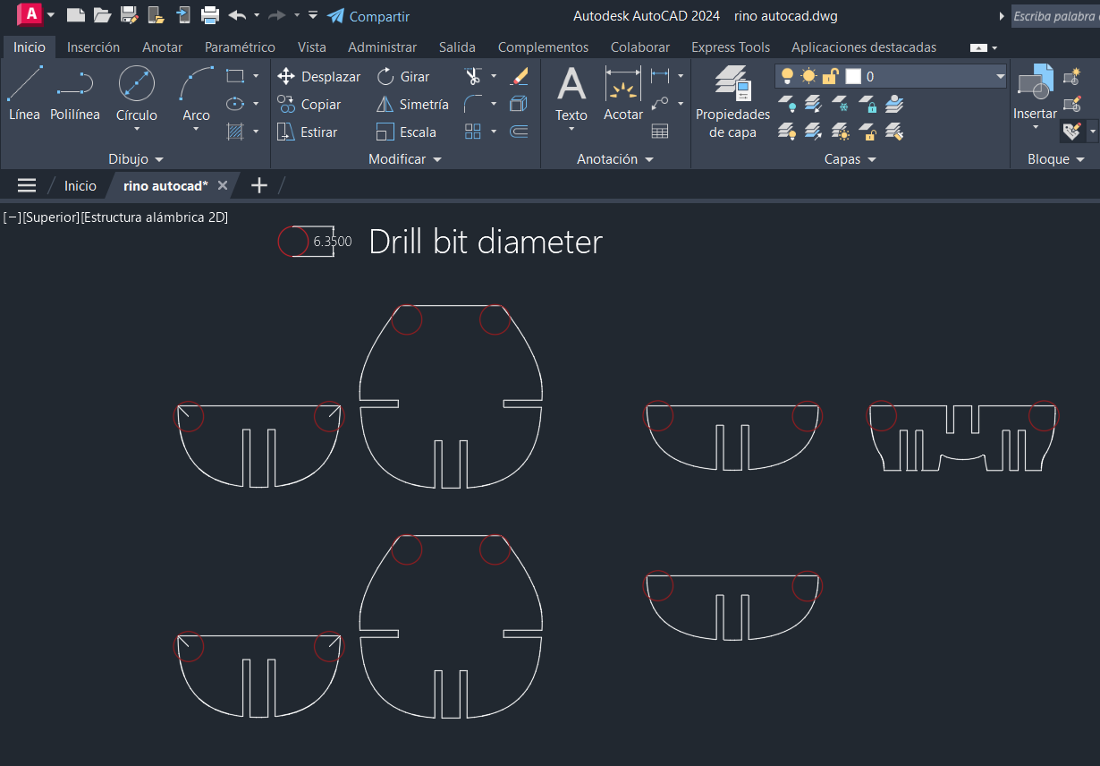
After adding the “Dogbones” to the design we must edit them and then start the cutting process. Remember that the diameter of the circle for each Dogbone must be equal to the diameter of the drill bit we will use.
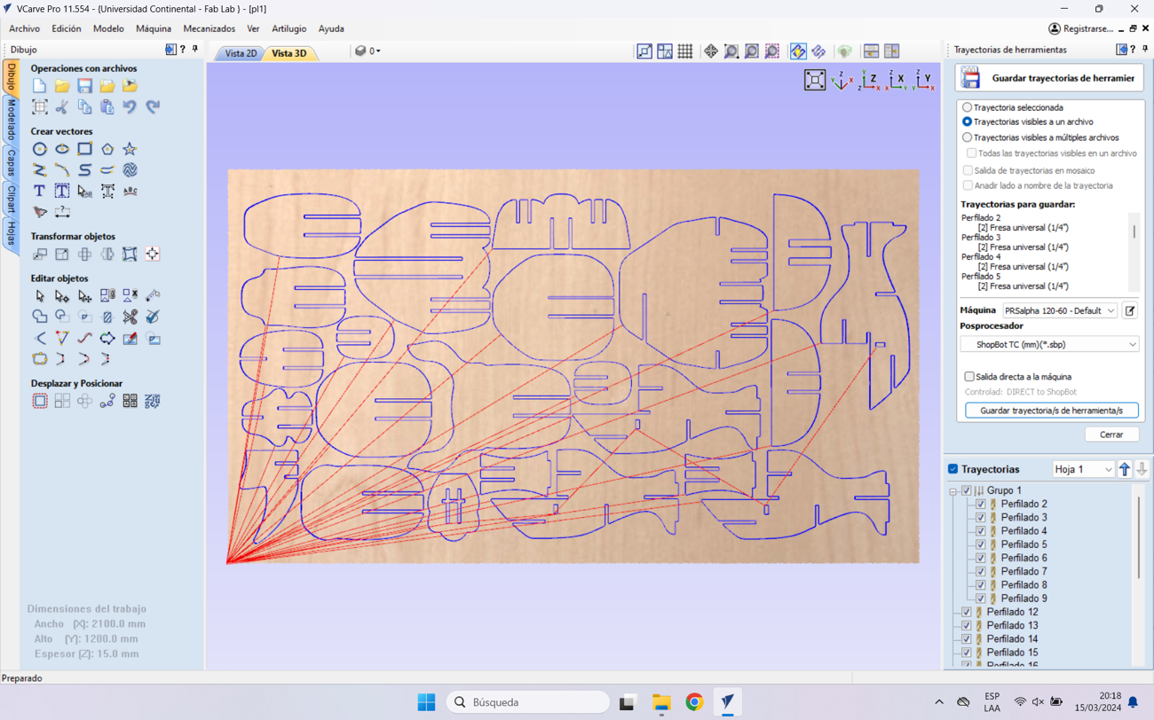
Let's see the process…
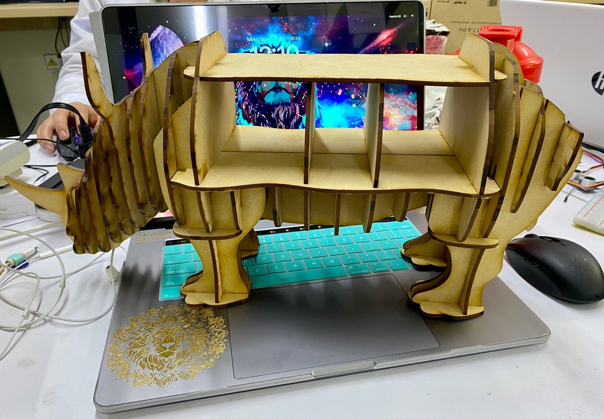
After cutting all the pieces, I began to assemble them and at first it was difficult because of the joints, because there was slight movement when pushing the piece into the socket. All the pieces went in without complications.
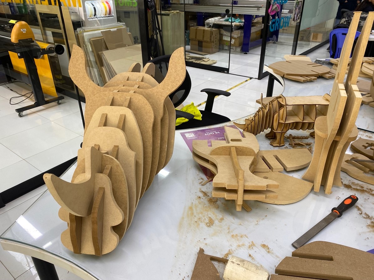
The final result turned out very well. The truth is that I really like the shape, I was amazed at how wonderful it is to go from a small scale to a large one.
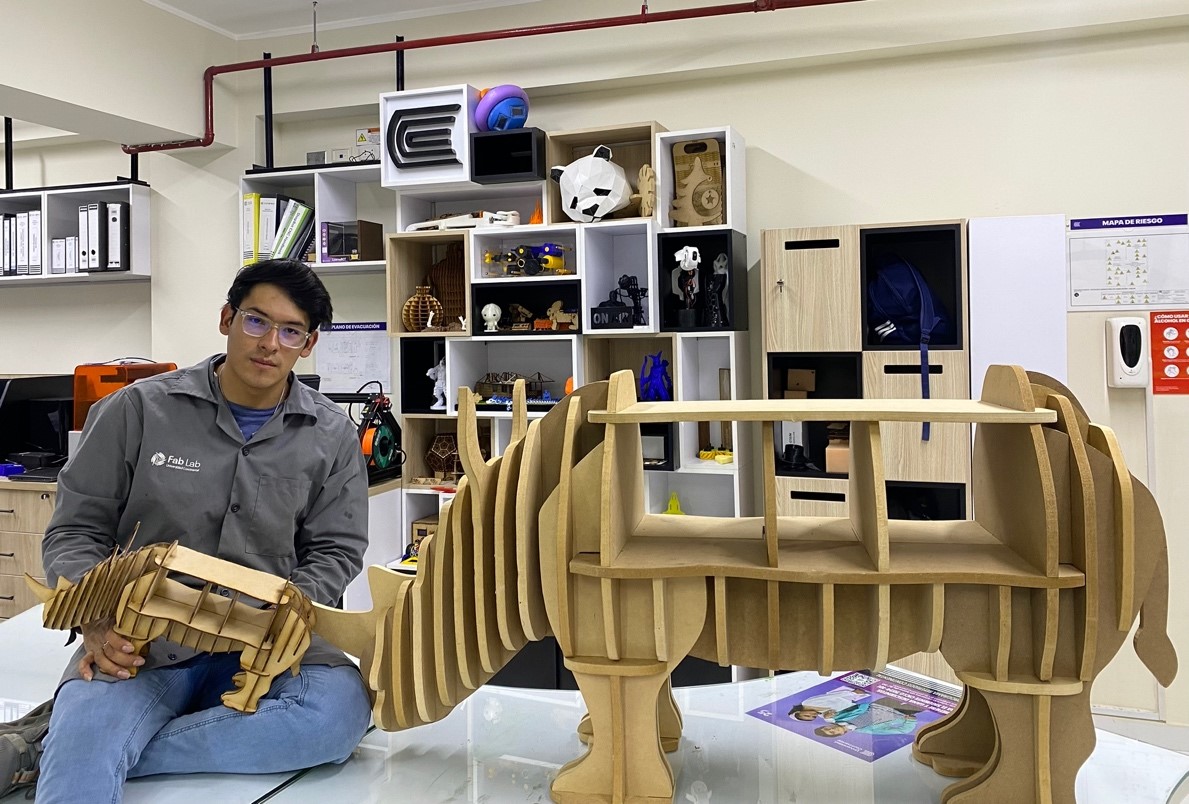
Now let's test its resistance….
Learning
Well we finished the assignment and we definitely did not take away important learnings:
o Before generating a large-scale cut, it is good to be able to perform a scale test since we can often identify errors when assembling.
o Take into account the parameters and offset of the machine when you want to make pressure assemblies.
That was all, I leave the files of this adventure here and see you next week….