
Welcome to Week 6
Electronics Design
Hello! this time, let’s learn about Electronics Design, for this week we have the following group and individual assignments:
- Group assignment:
- Individual assignment:
o Use the test equipment in your lab to observe the operation of a microcontroller circuit board (as a minimum, you should demonstrate the use of a multimeter and oscilloscope) - ✅ Done
o Document your work on the group work page and reflect what you learned on your individual page - ✅ Done
o Use an EDA tool to design a development board to interact and communicate with an embedded microcontroller - ✅ Done
GROUP ASSIGNMENT
Electronic design is the systematic process through which we create integrated circuits tailored to perform specific functions by leveraging electronic components.
First, as a group assignment, we will use test equipment, which we will see in the following image as well as the electronic components that we will use.
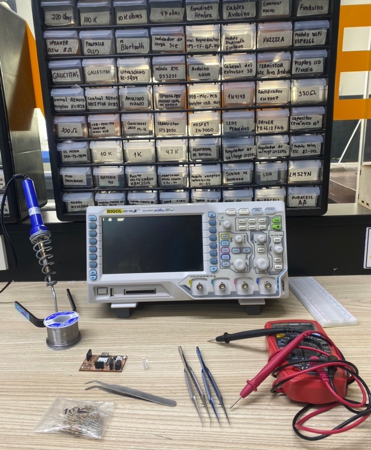
We will commence with testing using a multimeter.
To understand the functionality of the multimeter, we will initially examine the individual components before applying it to the board made during week 4 of electronic production. Our initial focus will be to determine the polarity of the Led.
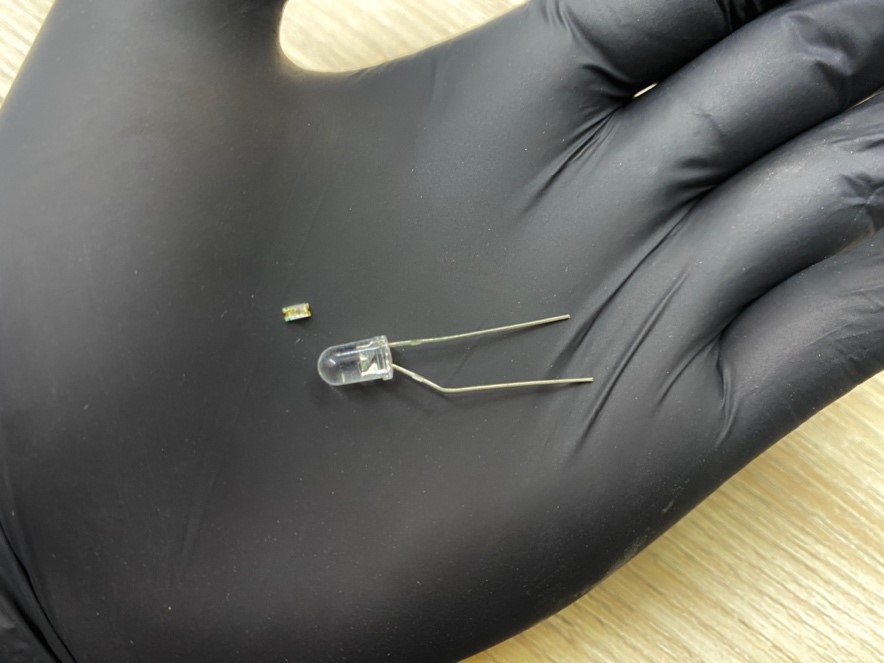
What we must remember is to find out which side of each Led is negative and which is positive. For Dip Leds, the shortest leg is always negative, while the longest is positive, for SMD Leds, there is a green mark indicating the negative side; the opposite side is positive.
To check the Leds we will use the "DIODE TEST" option of the multimeter. This configuration helps us verify if the leds are working correctly or if they are already inoperative.
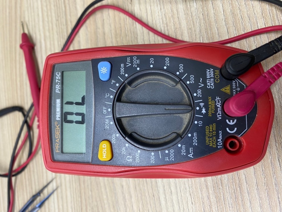
Here's the test we conducted with the SMD LED, demonstrating that its polarity is correct and it can be illuminated using our multimeter.
Next, we will proceed to test the resistors to determine their resistance values using the multimeter. To measure the resistance of our components, we will select the "Ω" symbol on the multimeter, which represents resistance. This configuration allows us to calculate the values accurately.
Now, we'll conduct a continuity test on the circuit board created during week 4 of the Fab Academy. It's crucial to ensure that the tracks on the board have continuity, indicating that they are properly connected. Using the multimeter, we'll select the continuity symbol. When the multimeter emits a sound, it confirms continuity, signifying that the components are connected. If no sound is emitted, it indicates a lack of continuity, suggesting that the components are not connected.
Now we will use the OSCILLOSCOPE that we have, we will test it on the board, taking as a reading the voltage output it produces, now we will see it on the equipment screen
INDIVIDUAL ASSIGNMENT
First I started thinking about what I could develop, my head was spinning with several ideas, however walking after work I saw a little boy playing with one of the toys that he wanted as a child but couldn't have it because I had most of my free time. He was available for additional readings and classes at school.
This toy is a pinball, which came with various games such as Tetris, cars, snake, among others.
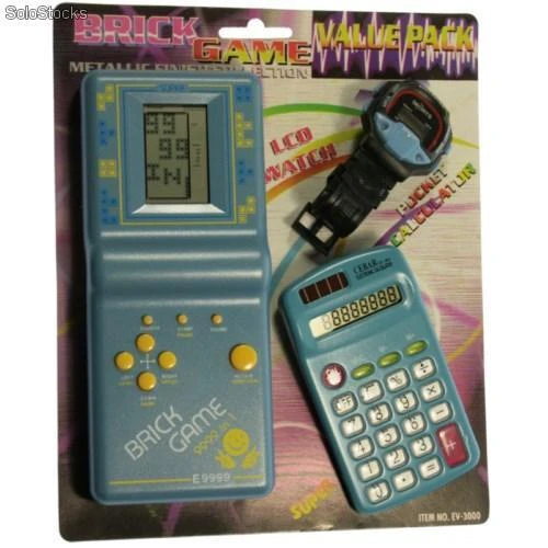
I still remember when they came with their watch and calculator, what times.......
Now, a short introduction on how to use the EasyEDA program.
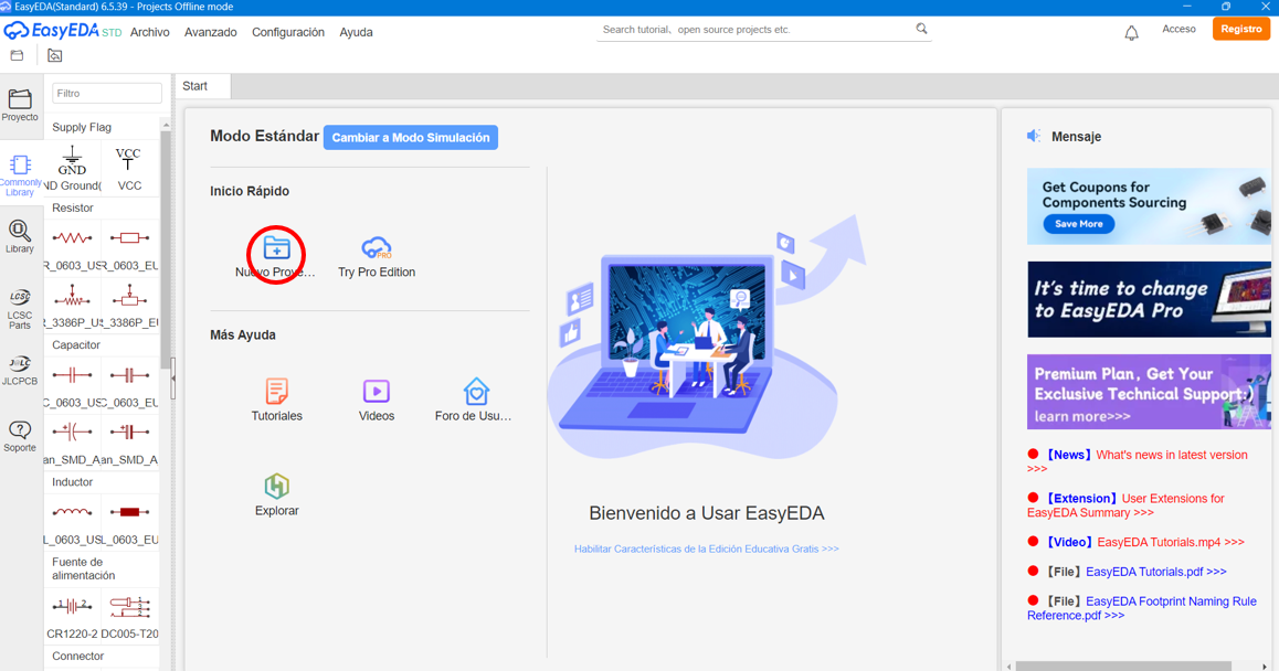
When opening the EasyEDA program, we create a new project by clicking on "New Project".
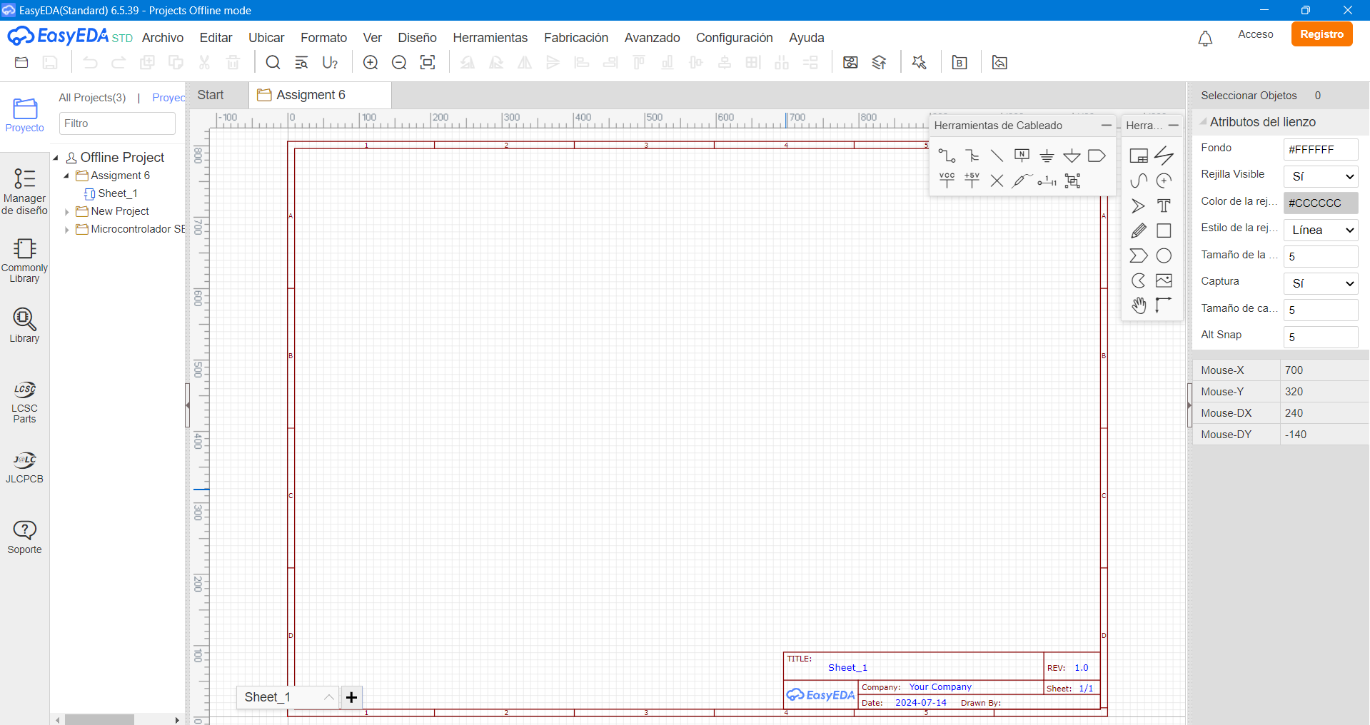
It will open the work area of our project that we are going to carry out which should look like this:
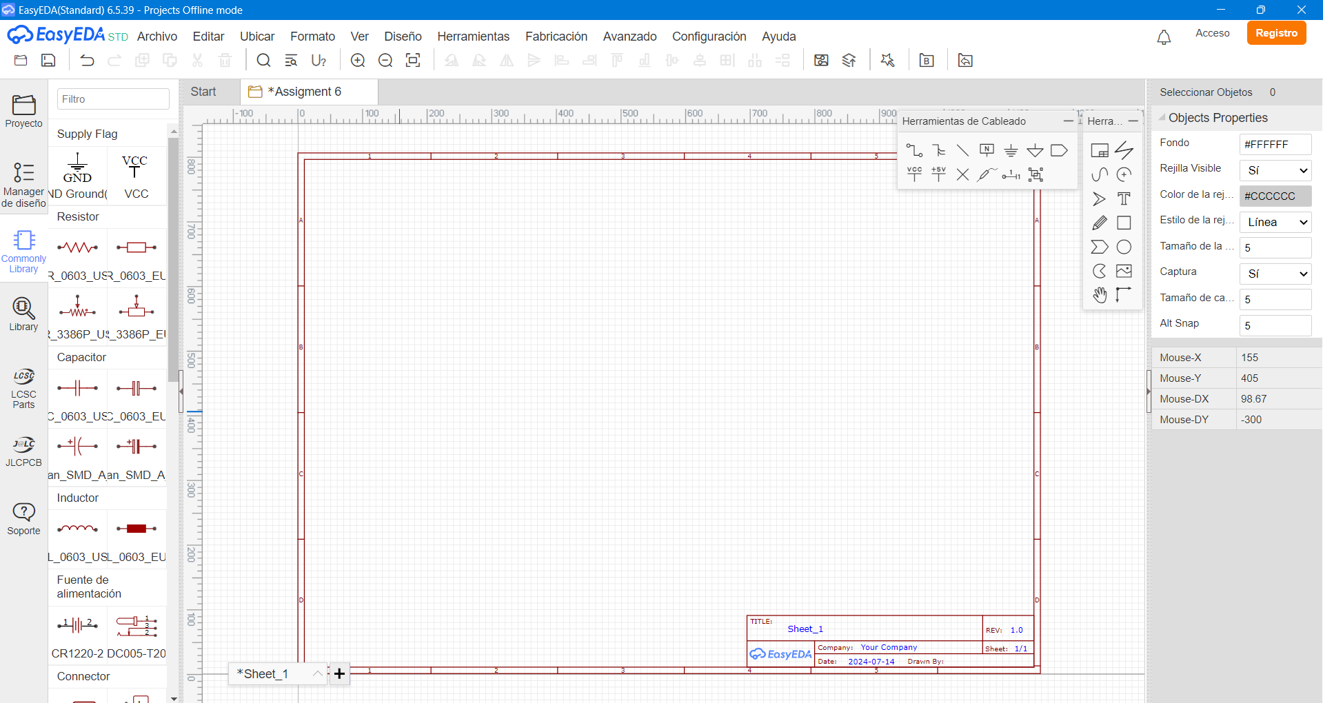
Once inside the work plane, we will add all the components with which we will work. By clicking on "Commonly library".
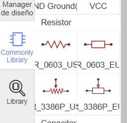
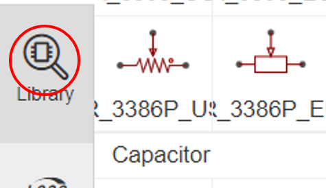
We will find several components and defaults of the same program. These can be selected according to what we need and we can also modify the values, and we can also choose whether we want the model in symbolic or standard form. Inside the library you can see on the left the symbolic model of a resistor, and on the right the standard model of this one.
It is true that within the "Commonly library" there is not much variety of components, that is why we will add the components that we will need to make our projects. We must click on "Library", it will be possible to differentiate it because it is a magnifying glass on the left side.
A window will open showing all the components that can be used.
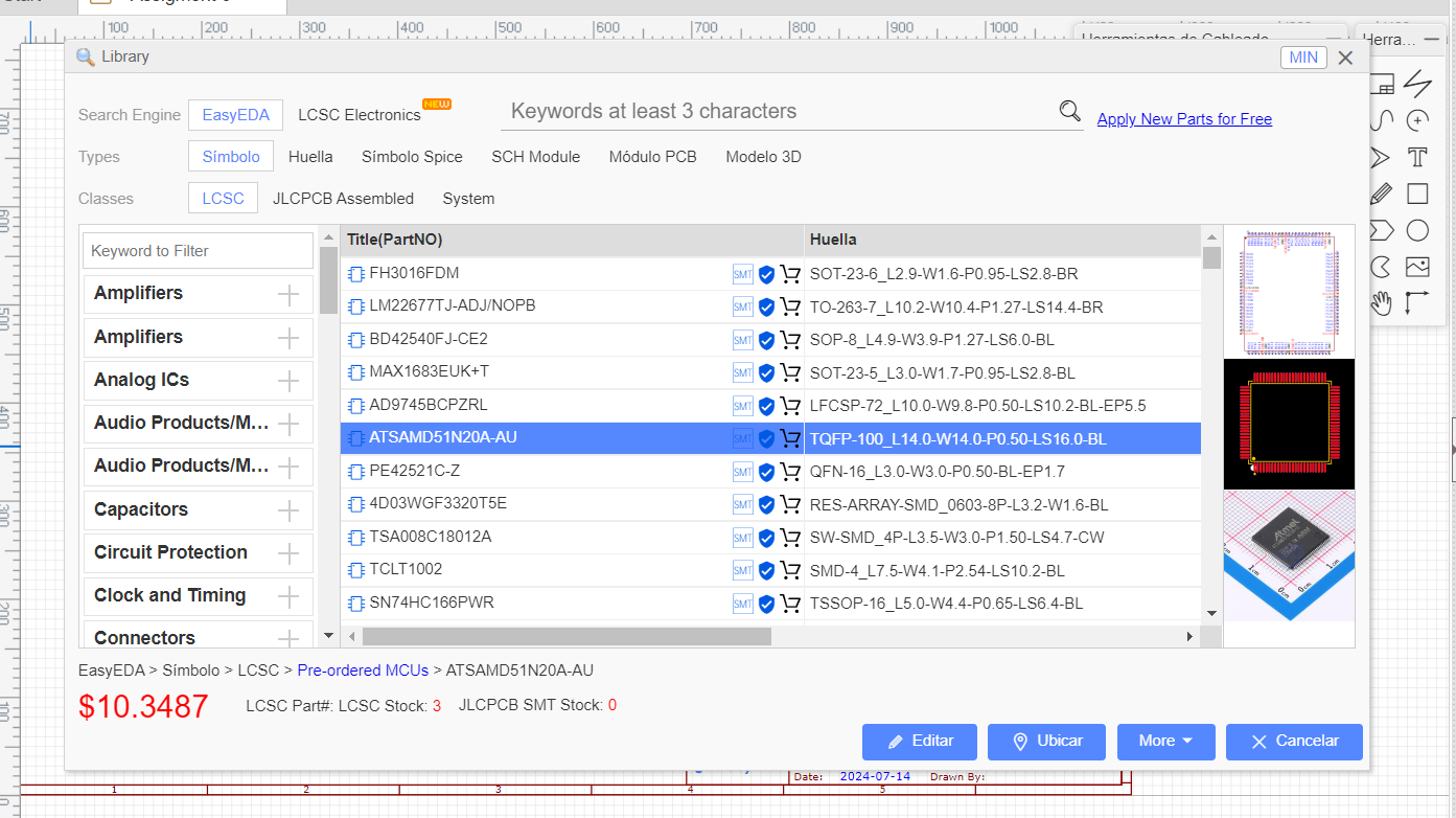
We look for the name or code of the component we will use and select it. We will make an example of lighting an LED to continue explaining.
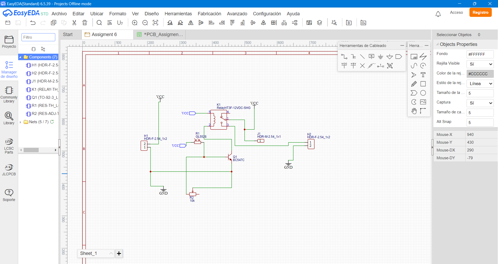
After making the connections of our circuit.
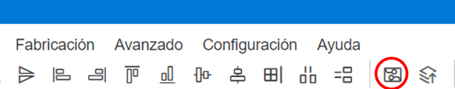
Select everything, save by pressing "Ctrl + S" and convert the design to schematic model by clicking on "Convert to schematic PCB", it is located in the toolbar:
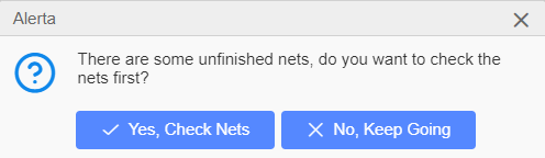
If the connections are not properly made, an alert will be displayed, if we want to verify we press Yes, and if we want to preview we press No.
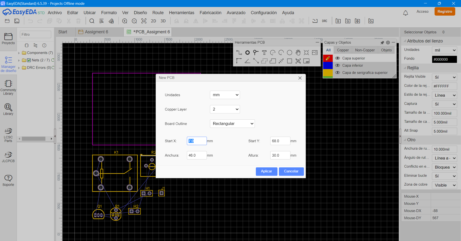
After having modified our board, we move the components inside the pink rectangle, since that is our board.
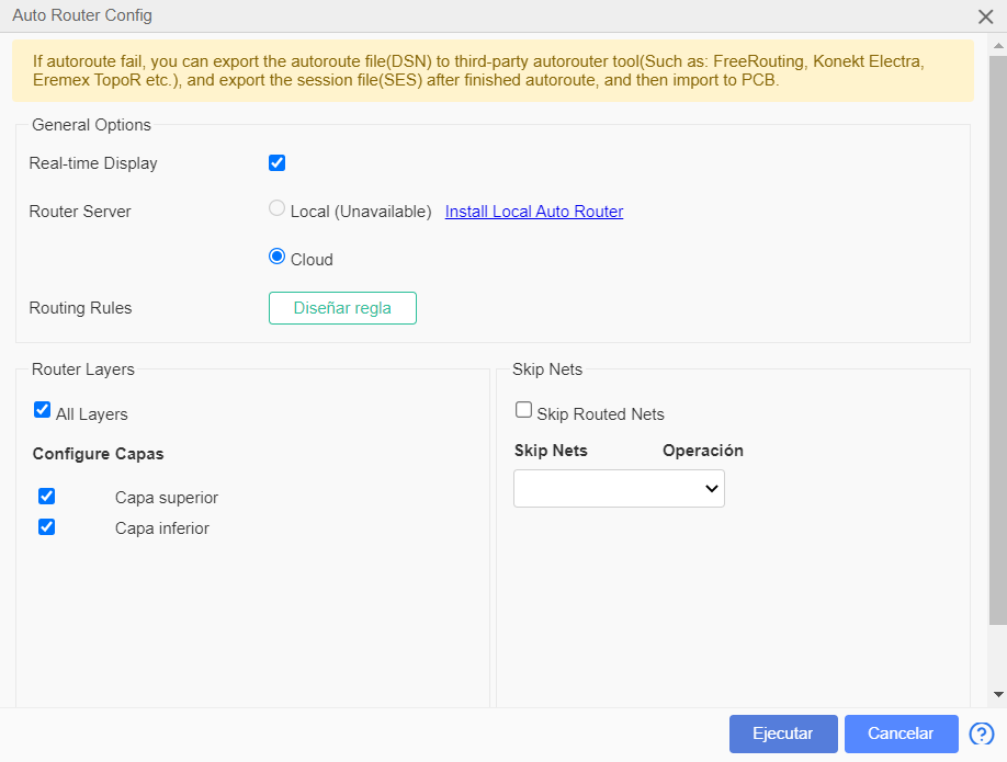
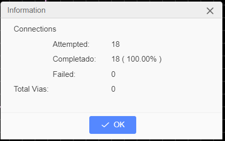
Save with the command "Ctrl + S". Select everything and in the toolbar look for the "Route" option, options will be displayed and there we select "Auto Routing". A box will appear. Select our configuration and click on "Execute". Then we will get an information box where we get the connections made, if there is a bad connection the routing will not be done.
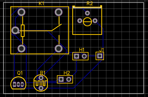
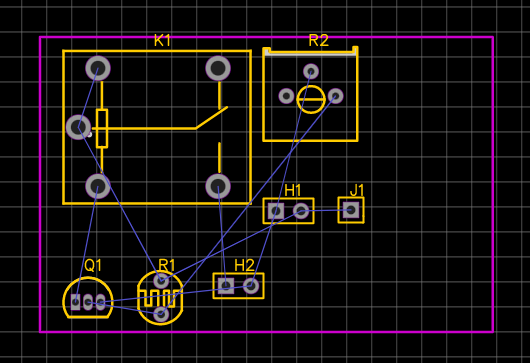
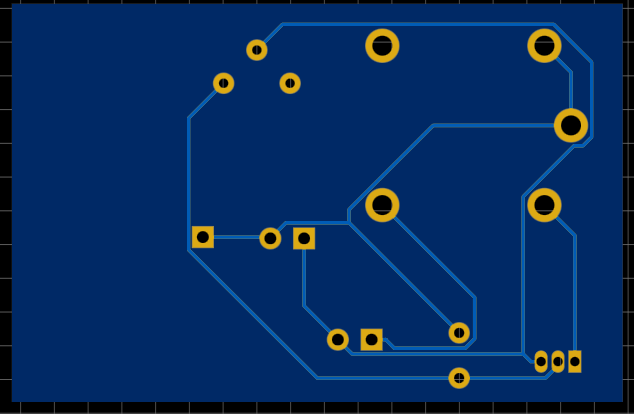
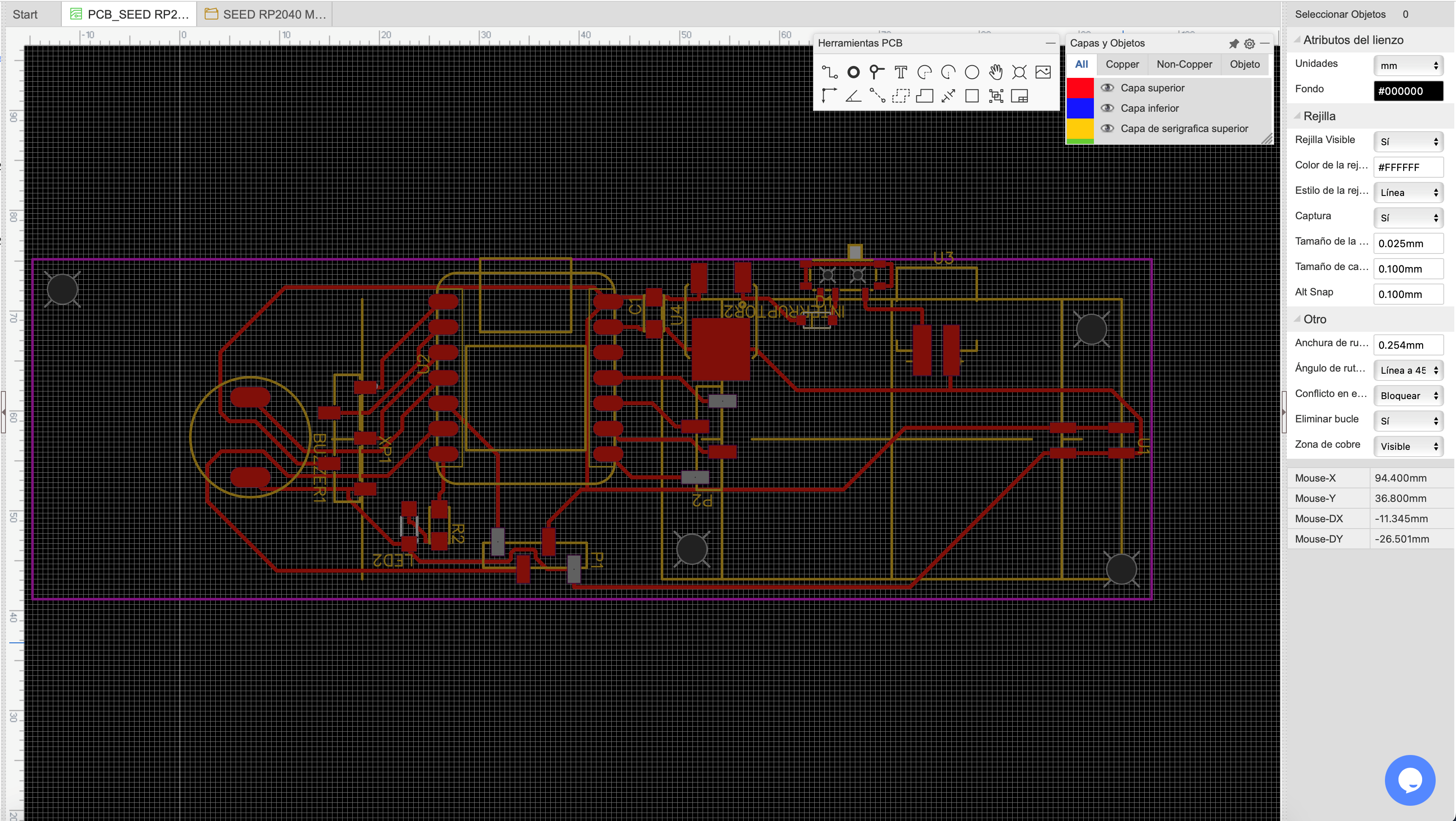
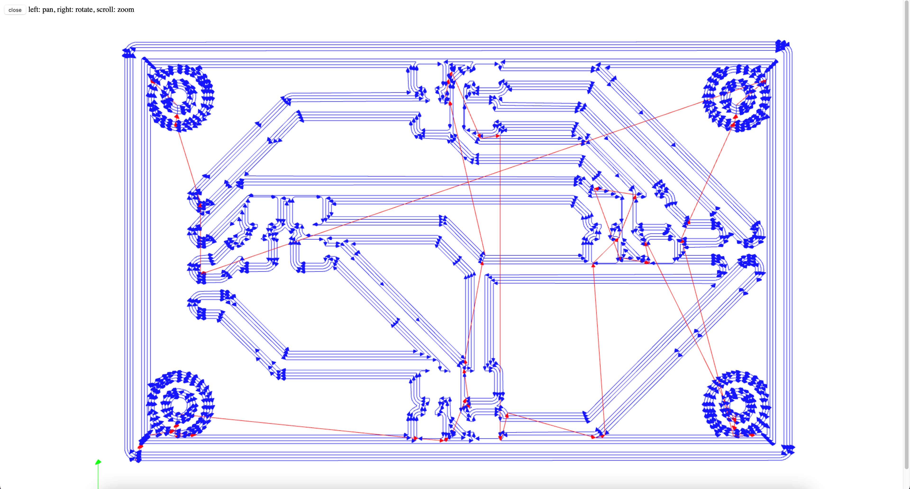
View of the routing on the plate:
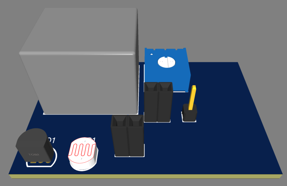
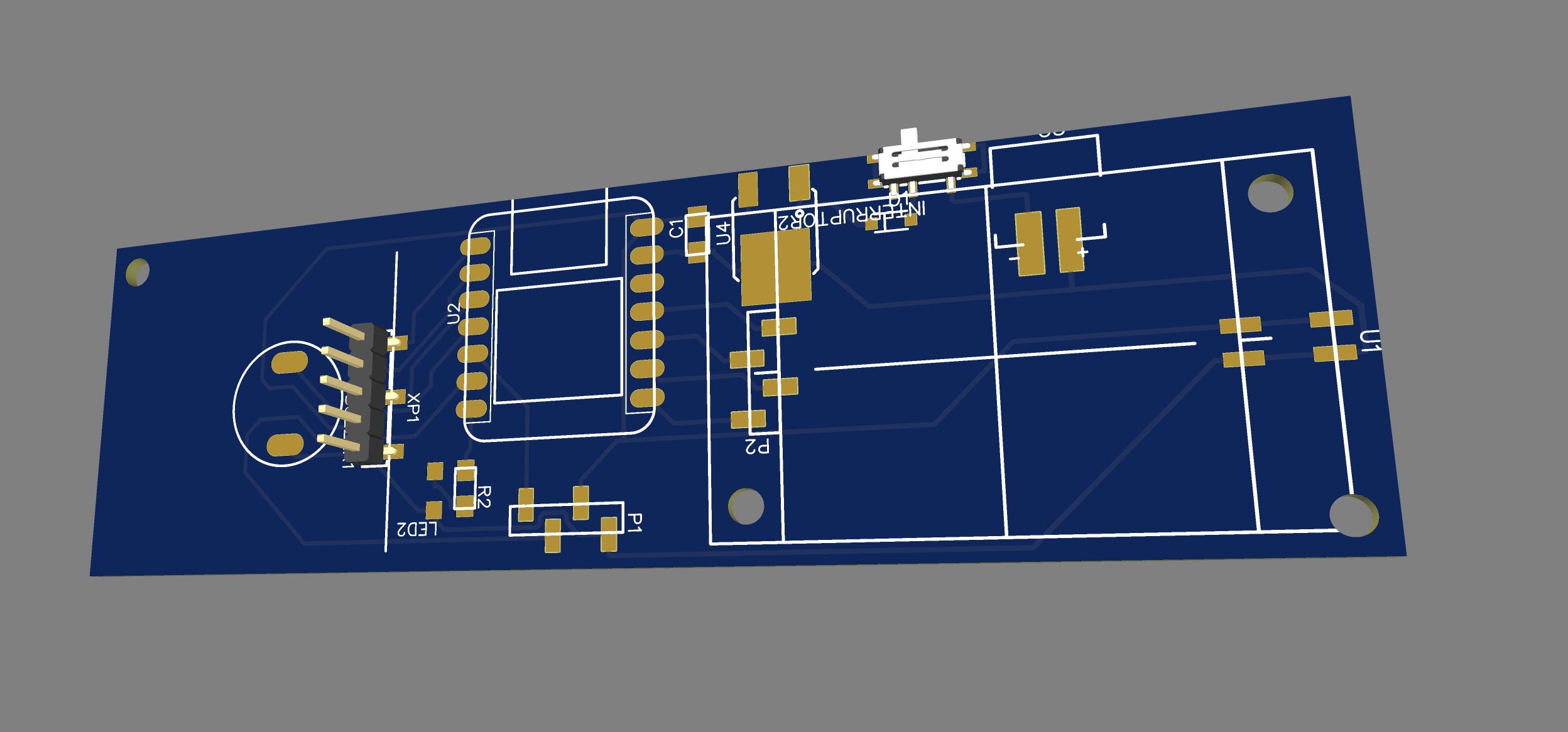
3D view, with components:
And ready, we export the model to the MODS CE page, to make the milling in the CNC and we would have our board and ready to put the components and solder them.
Remember that this is an example, but not the project to be carried out. So don't get confused hehe.
If you want to learn more about how to make each design, the EasyEDA program itself has its tutorials to learn from 0. Here is the link to the tutorial: Tutorial
So, let's get to work! To achieve this idea, we will work with the Easy Eda program, in which we will develop the board, placing a screen in this case OLED, some buttons and of course a joystick to make it modern, with the help of the Seeed xiao RP2040.
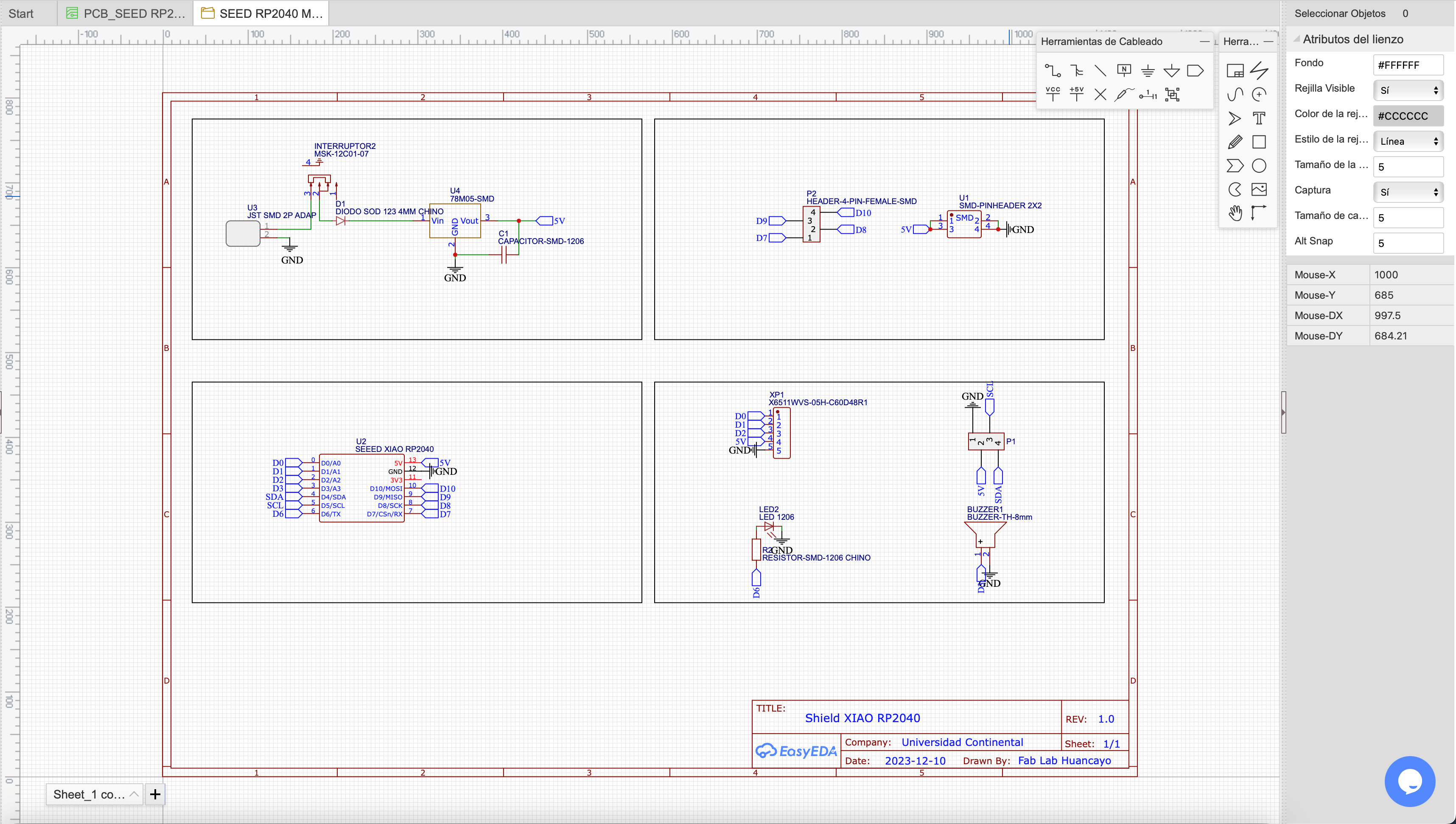
Here we will be shown the components that we use, and we must position and connect them.
Your 3d model would look like this:
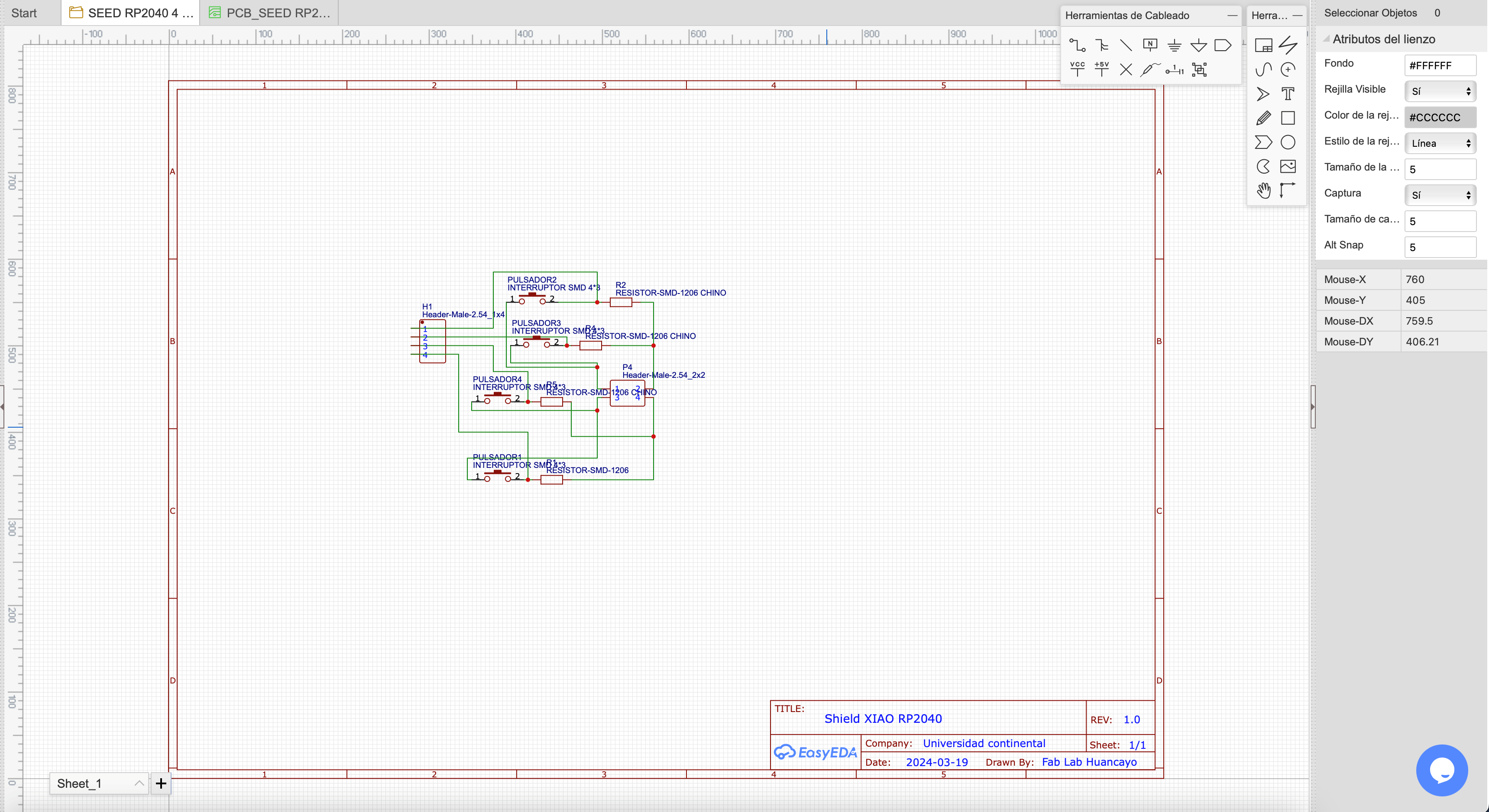
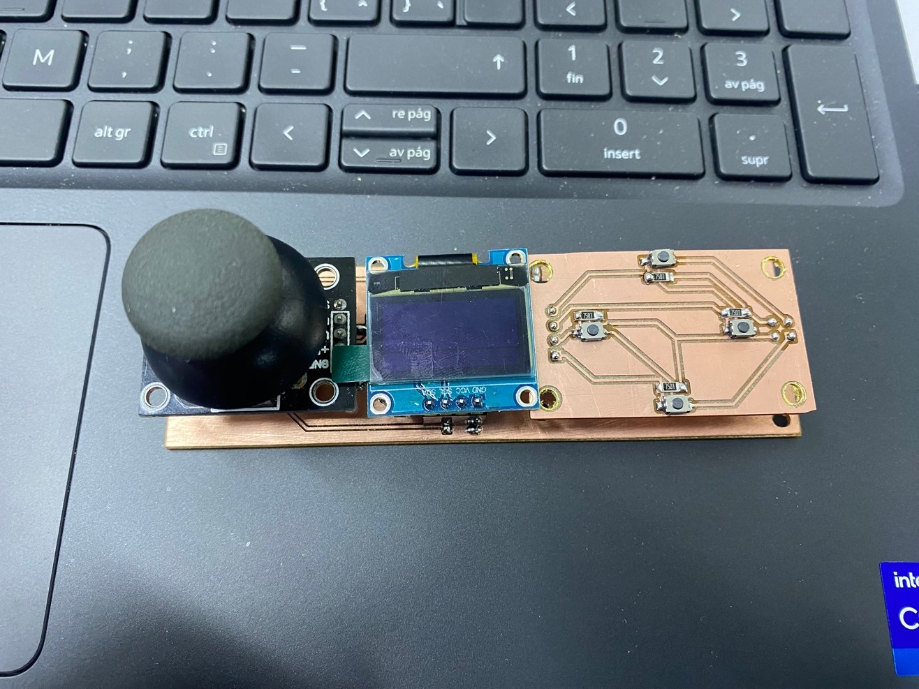
We will also make a small plate with 4 buttons that will help us in the various games that we are going to simulate.
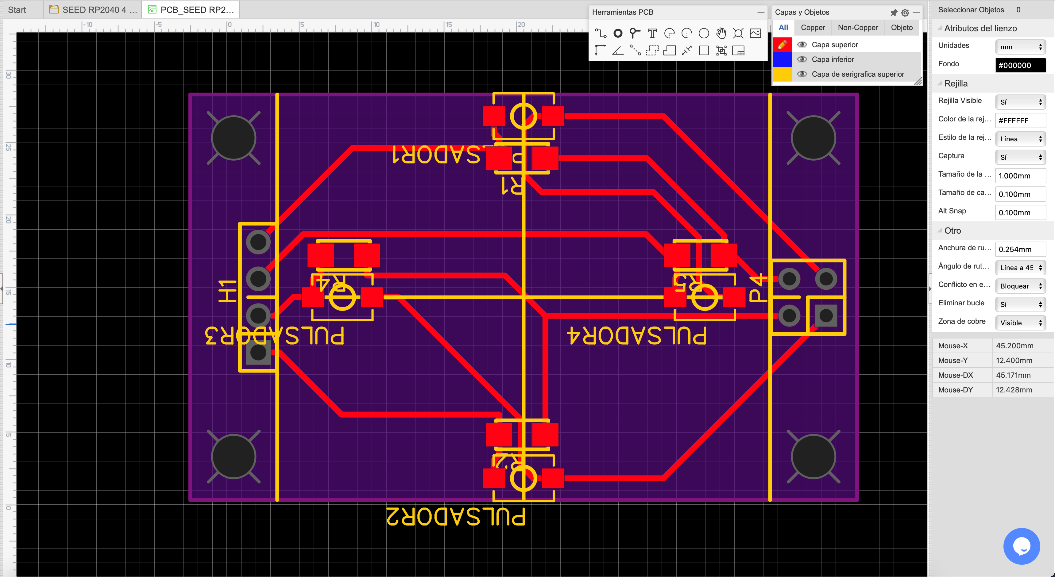
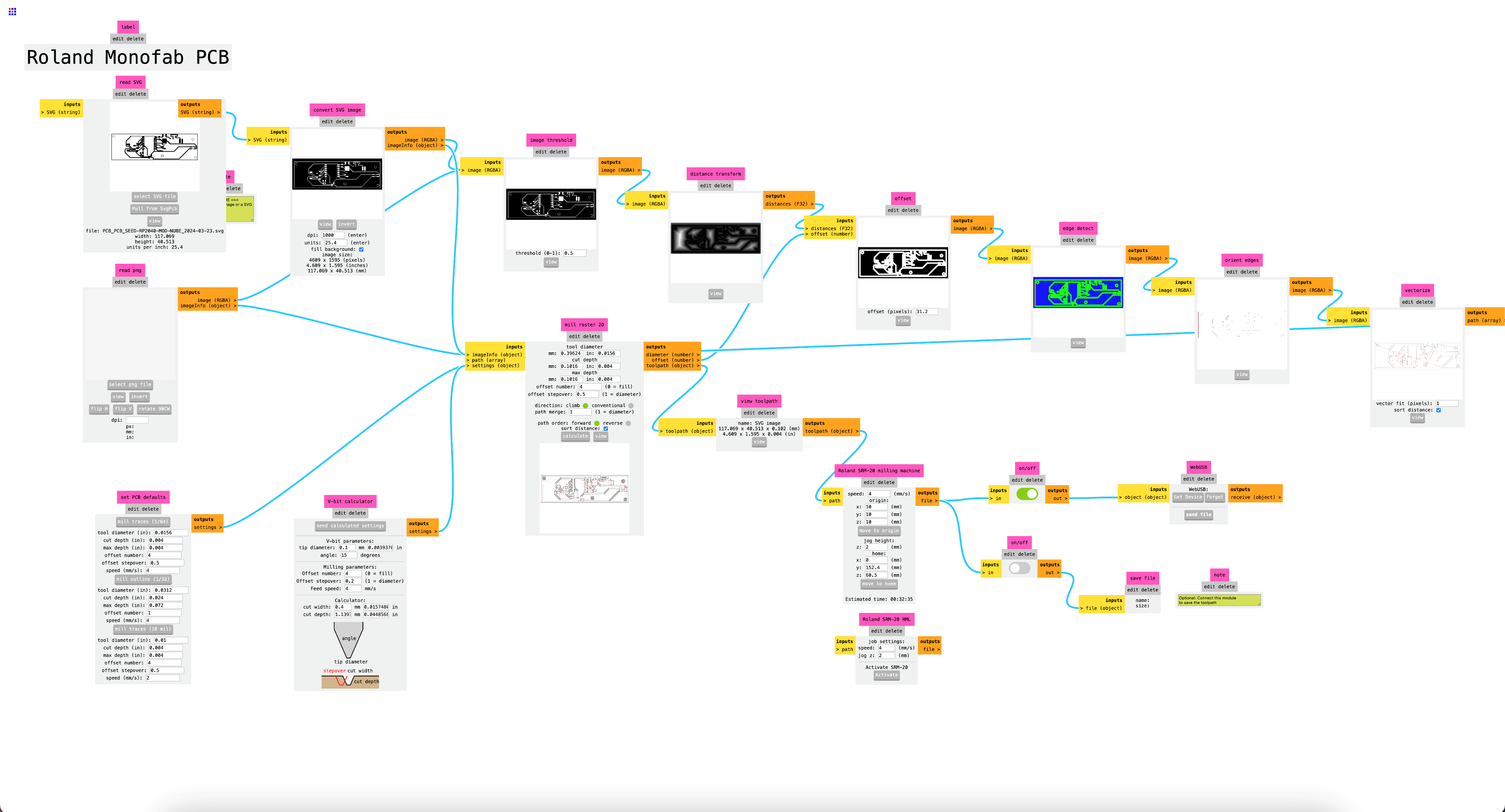
We export to MODS CE:
Also the button plate:
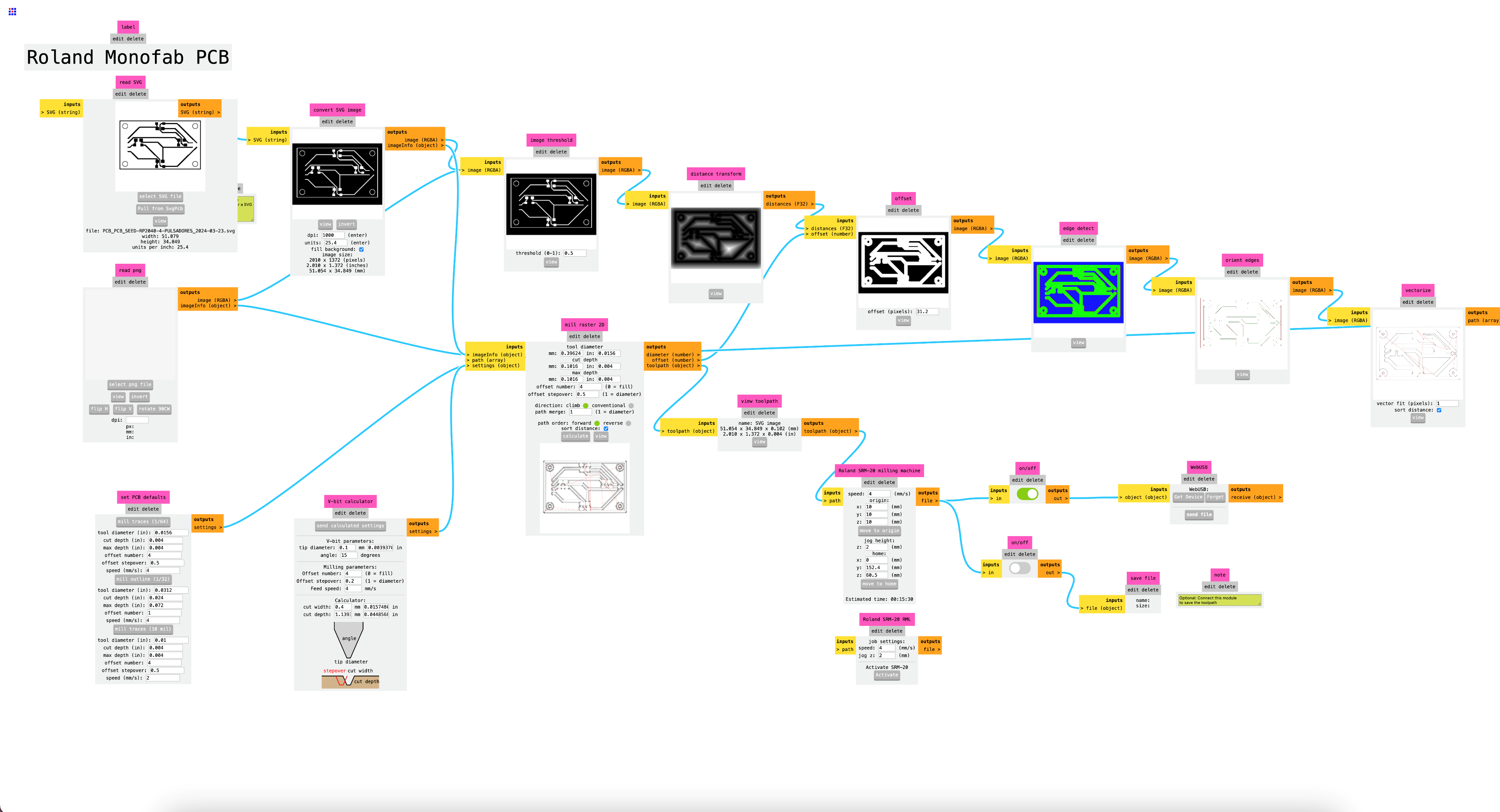
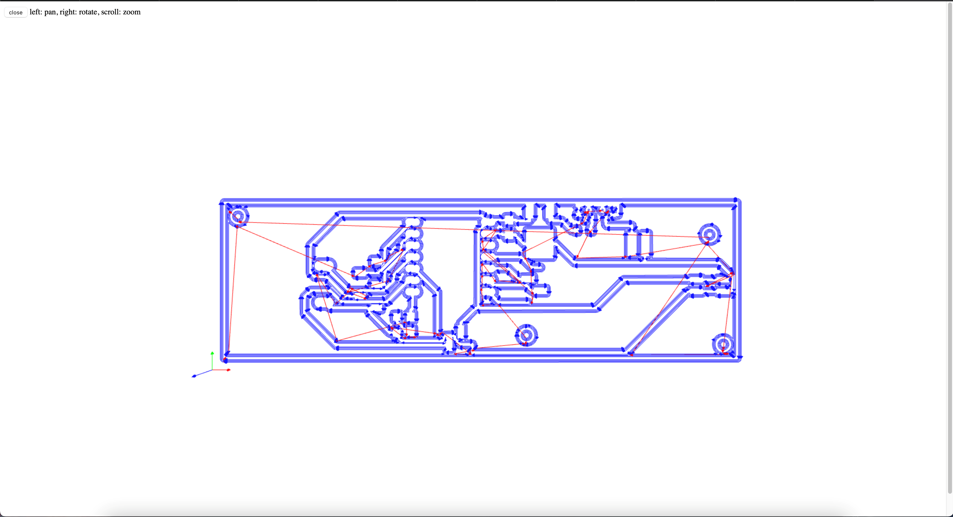
After configuring and verifying our files in MODS CE, we will proceed to mill our board. We'll start by milling the traces followed by the perimeter of the board.
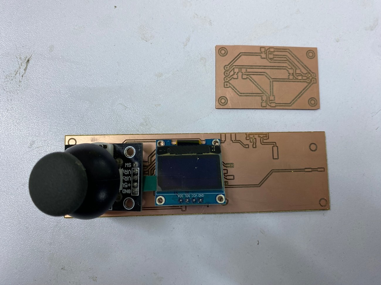
Let's see how our plate turns out
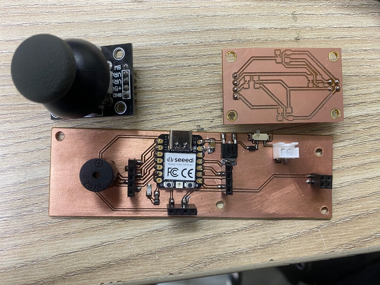
Ready, we already have the plates and they look good, let's continue with the soldering process
and by the magic of the academy..........
We already have our plate ready and it only cost us a couple of burns on our fingers.
It looked great, now let's design a case for our pinball, I will make it transparent so you can see the components
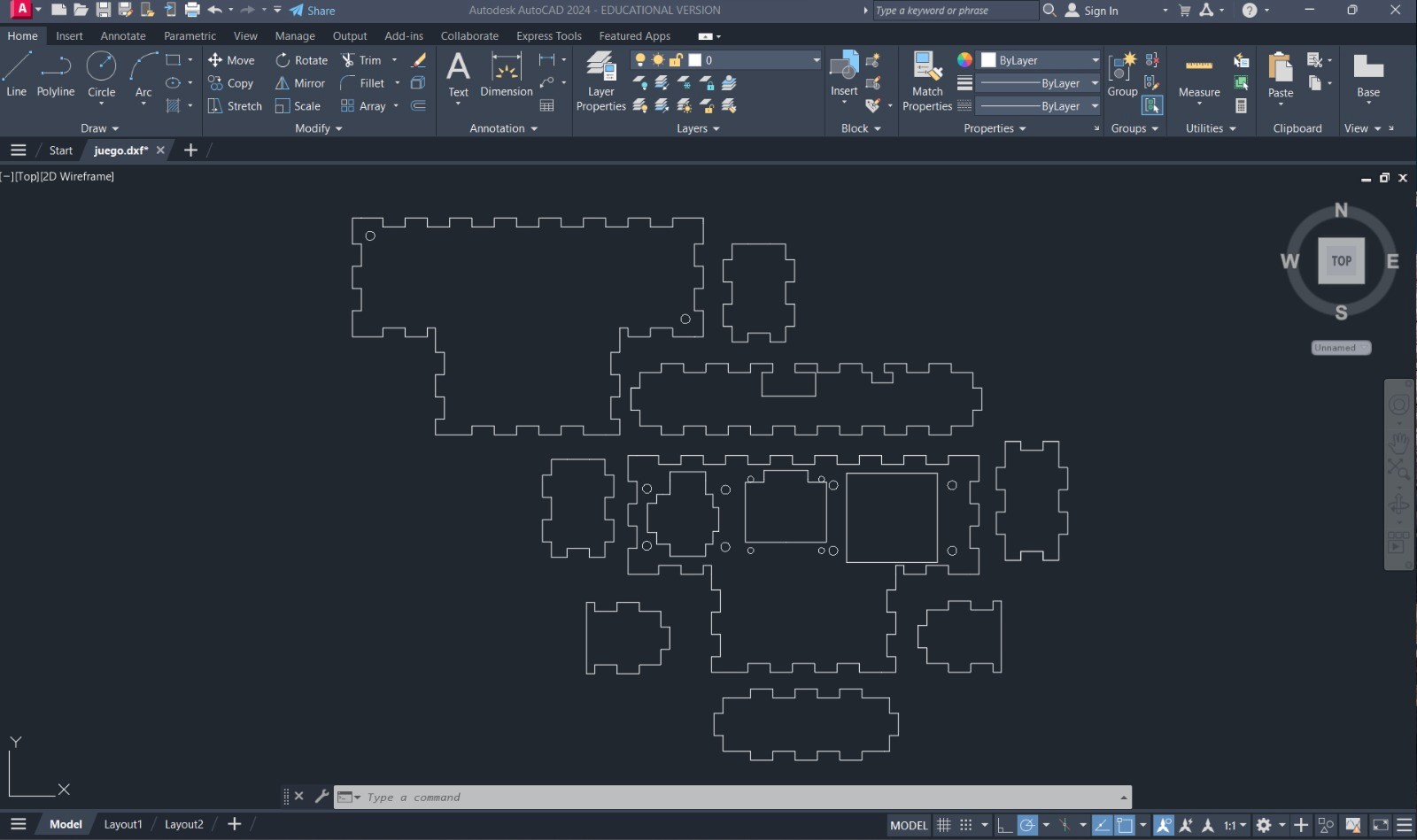
It looks good but let's cut it, I want to assemble it and see how great it looks.
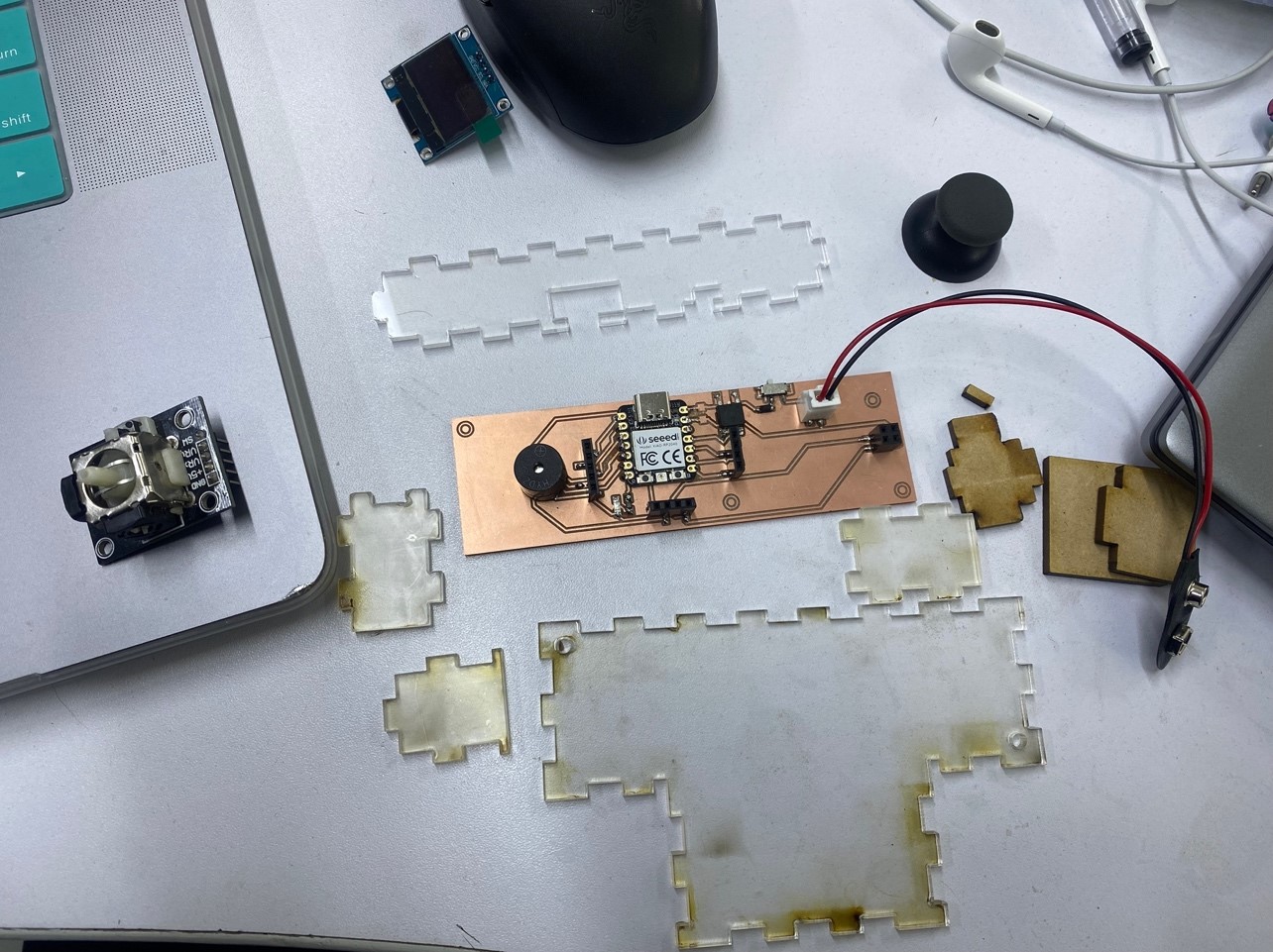
The dark ones are in the acrylic protector. When we finish assembling, we remove it and you will see that it looks very good.
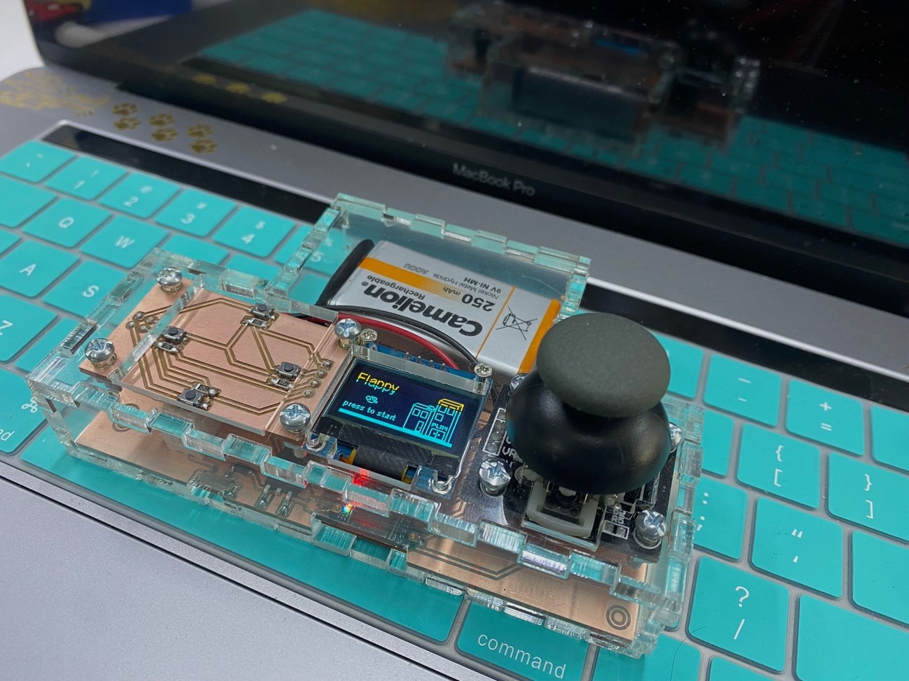
I managed to emulate the flappy game on the board. I will leave the files here, since there are several lines, it was somewhat complicated to find help to develop it until I saw Chinese tutorials, but it was done! Let's see how the game turned out
The game turned out well and I put in its battery so I could play it without having it connected to the computer, but the sensitivity is still very high so I calibrated the noise threshold values as well as the rise sensitivity and this is version 2 of the programming .
What I thought was achieved, all the files of this adventure you will find here, I hope that if you decide to do it you have as much fun as I did and it reminds you a little of the childhood that many of us put aside to give more time to our responsibilities
Here is the link to the software we are using in case you want to download it and try it yourself: EasyEDA
Here are all the project files: Download Here
Learning
Well we finished the assignment and we definitely did not take away important learnings:
o It must always be taken into account within the electronic design that this process must be complemented with a structural design so let's place the components so that they can fit with a casing.
o Normal components and SMS are the same in terms of function, however surface mounting is easier to handle and develop.
That`s All my friends, see you next week.