On the Wednesday of tenth week, Mr. Neil sir conducted our tenth global session. He took the random generator in first 90 minutes. He gave us overall explaination about week-10 which includes Mechanical Design and Machine Design.
Firmware and Interfacing
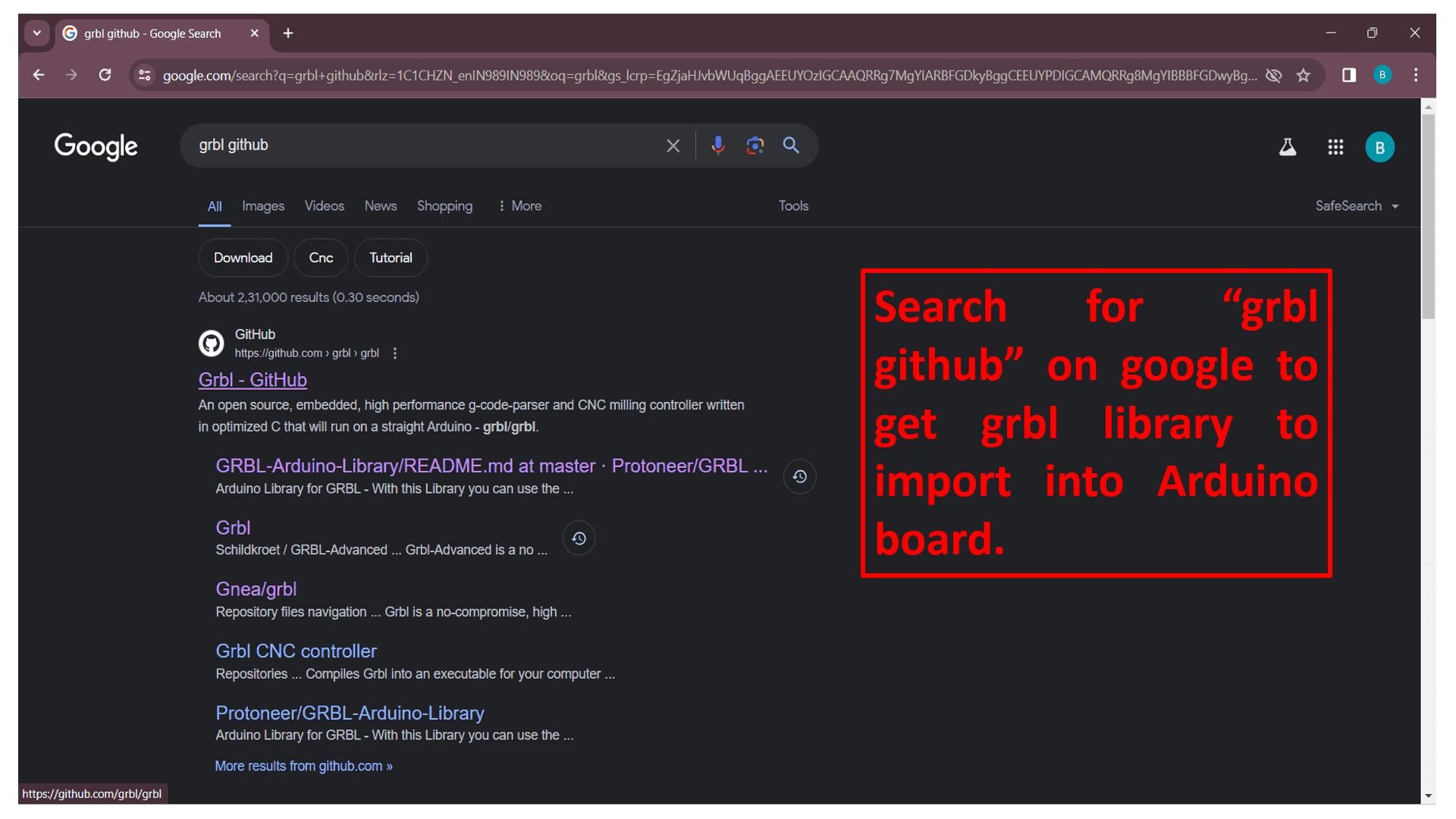
Firstly, search "grbl Github" on google or click on 👉 grbl github to get grbl file to import in Arduino board for machine work.
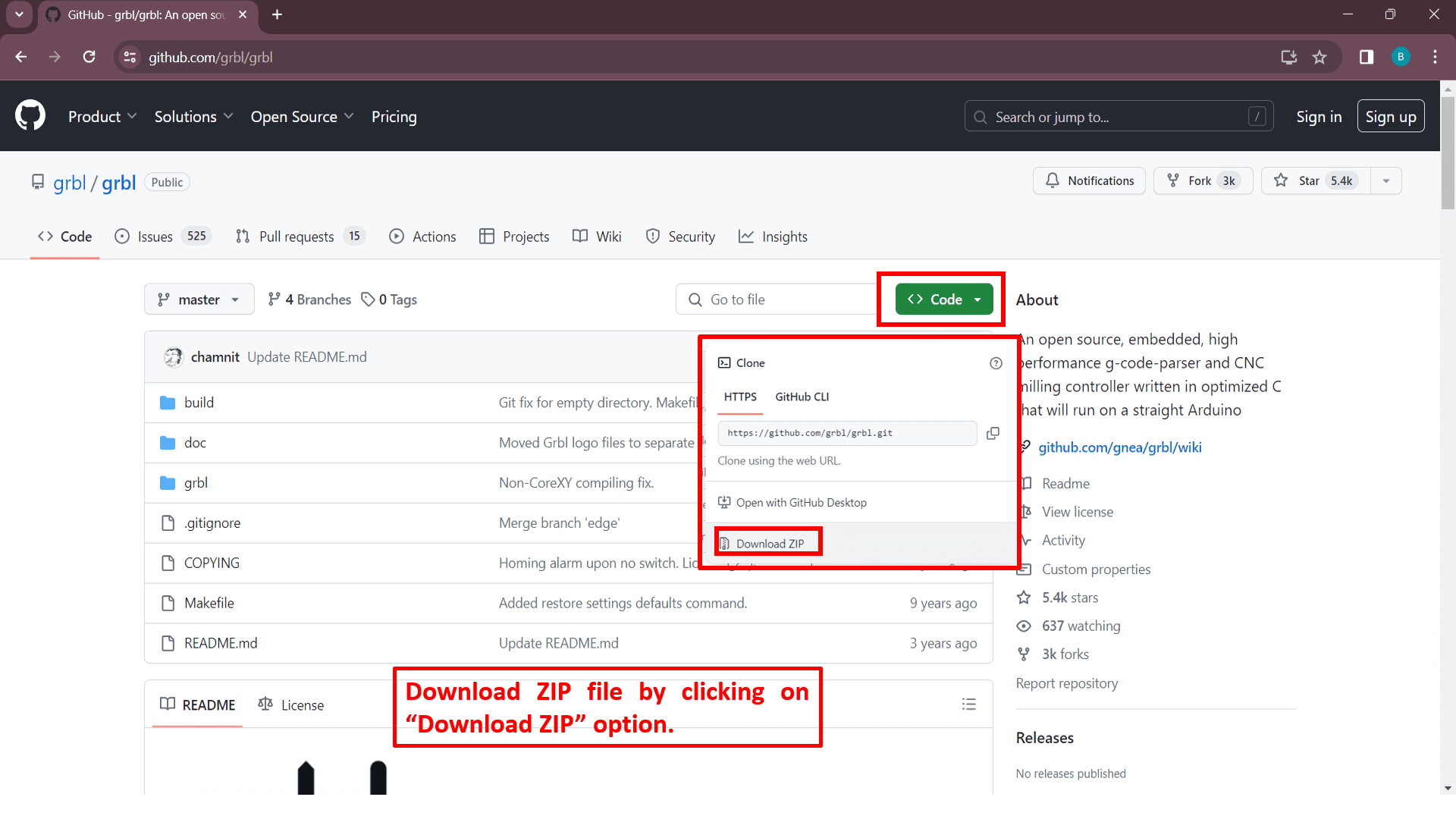
Now, download zip file by clicking on "Download ZIP" option which is situated in the drop down list of "Code" button.
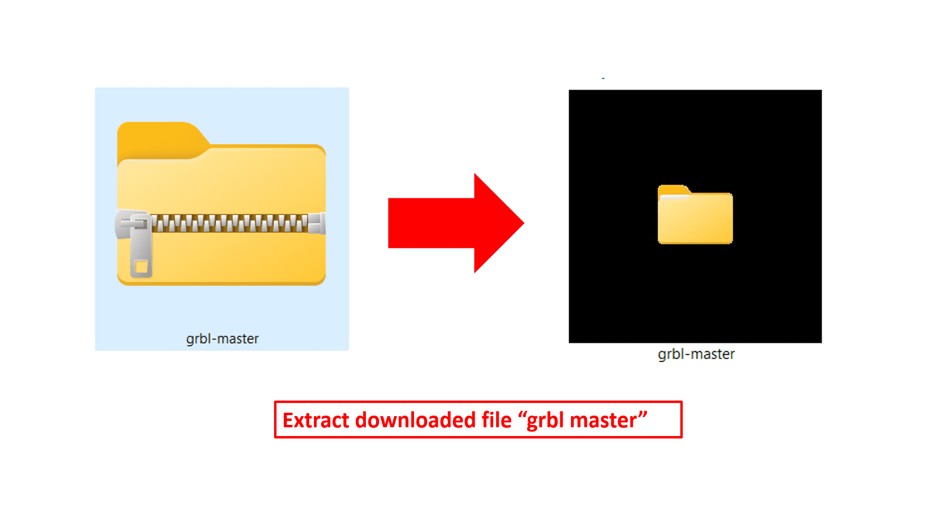
Extract the downloaded ZIP file by clicking on "Extract All" option by clicking on right click.
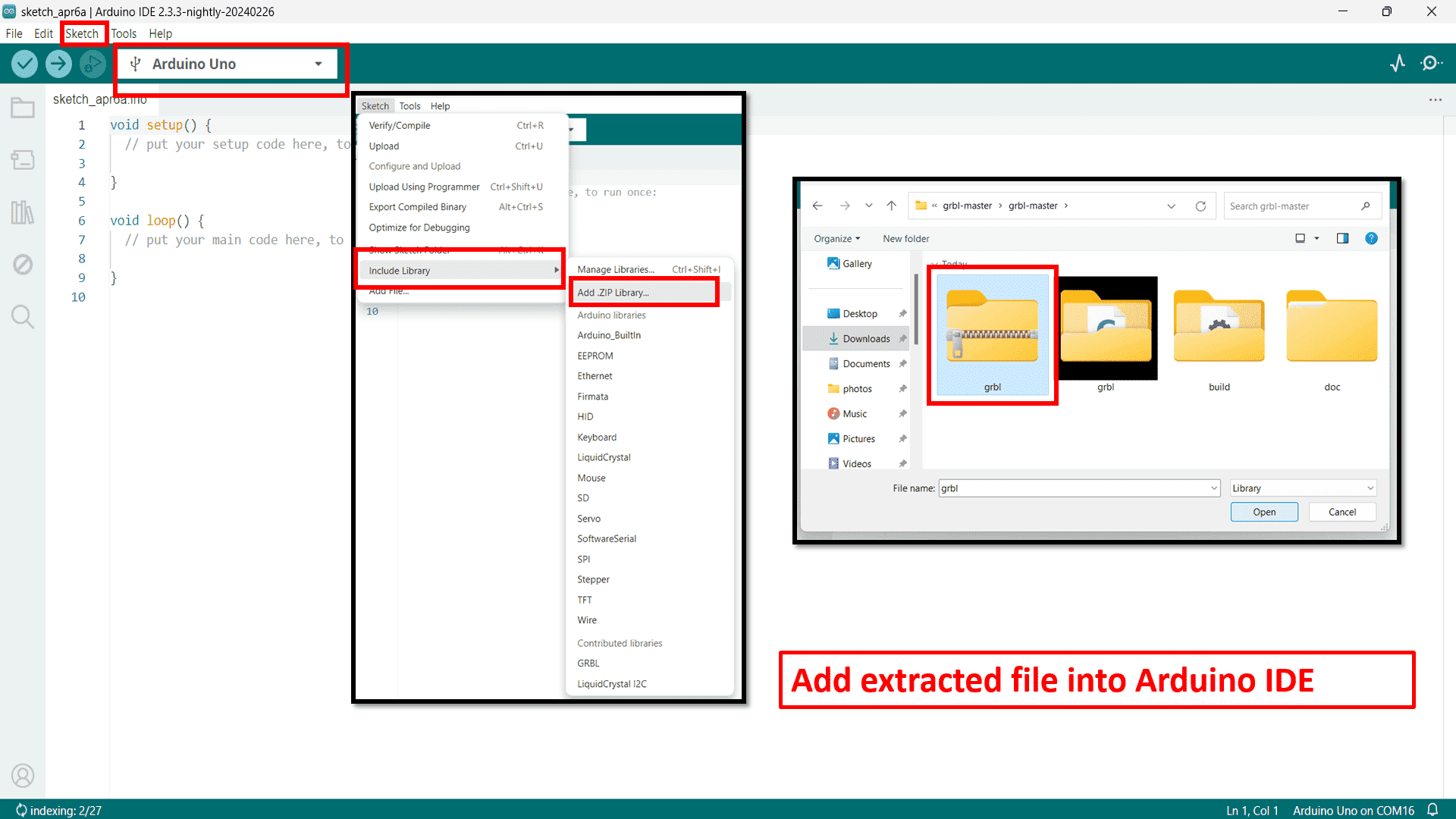
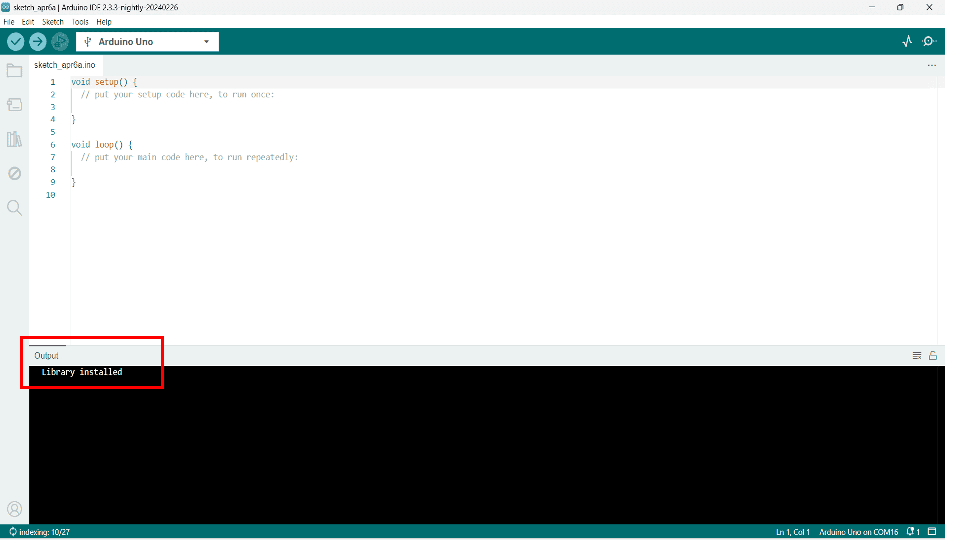
Open Arduino IDE and firstly select board type-Arduino UNO. Then, add "grbl" ZIP file which we have taken from extracted "grbl master" file by going to include library option situated in "Sketch" option.
Now, the library is installed into Arduino IDE.
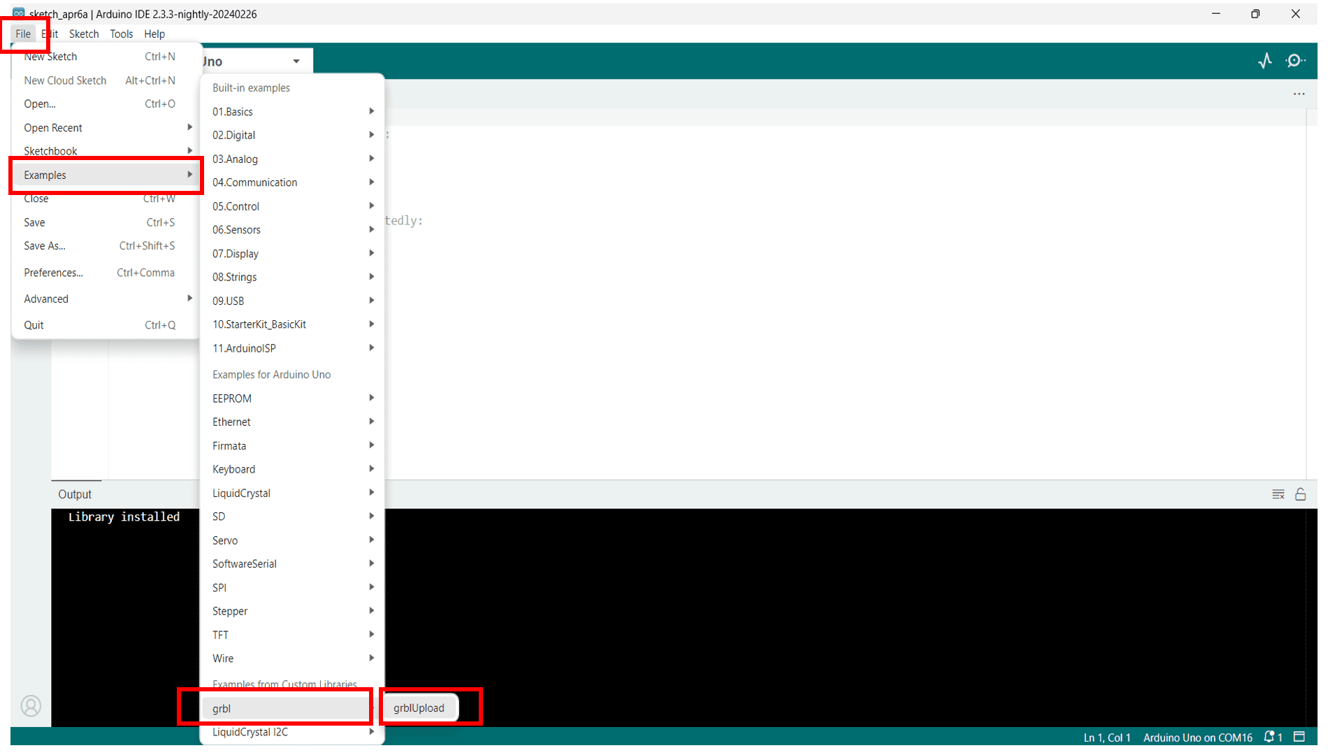
Go to "Examples" option located in the dropdown list of "File" option and upload installed library in IDE.
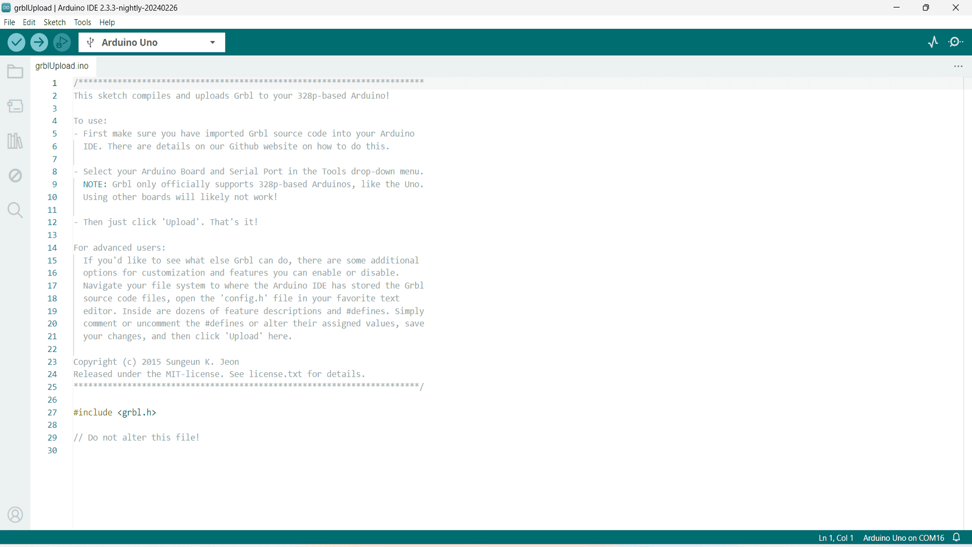
Here is the library of grbl firmware.
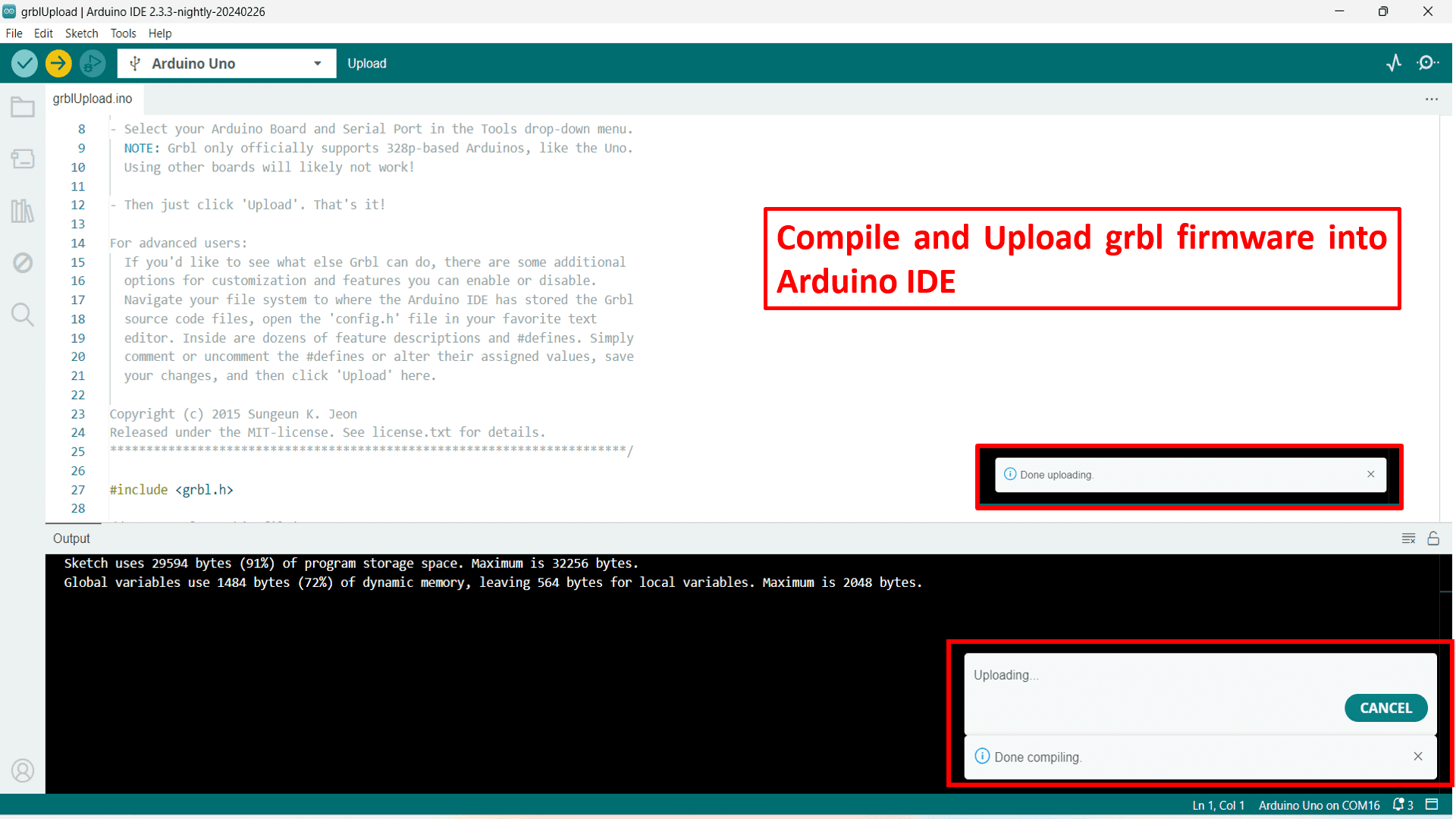
Now, Compile the code and upload it into Arduino board. Finally the firmware uploading is done.
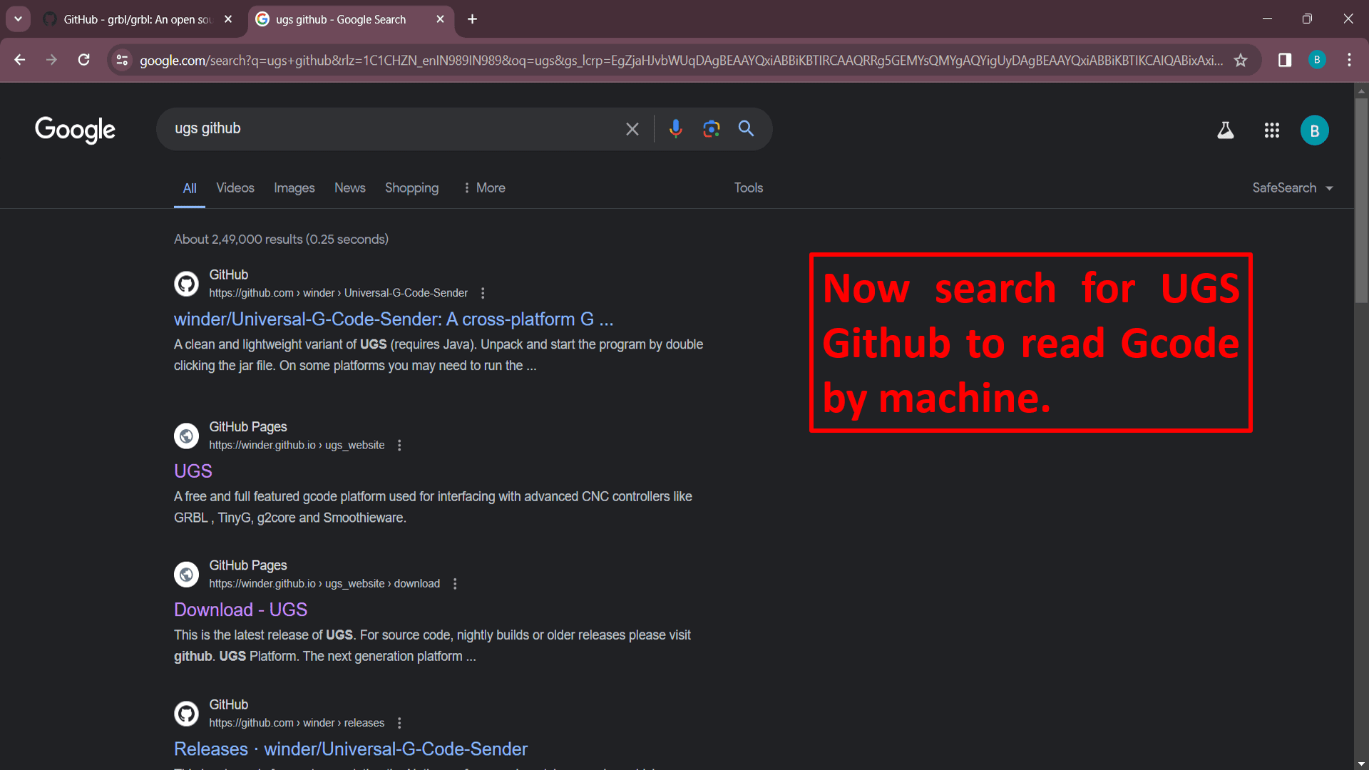
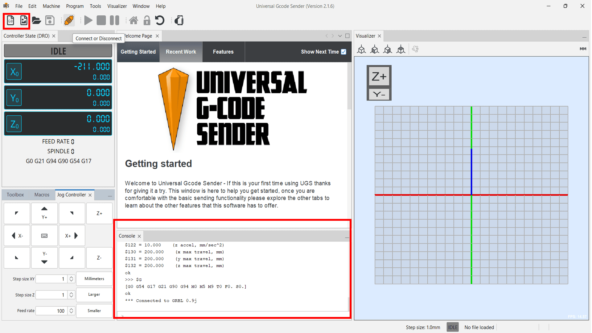
Now, to operate our machine we needed Graphical User Interface. So, we decided to use UGS-Universal GCode Sender. To download this open source GUI, again search "ugs github" on google.
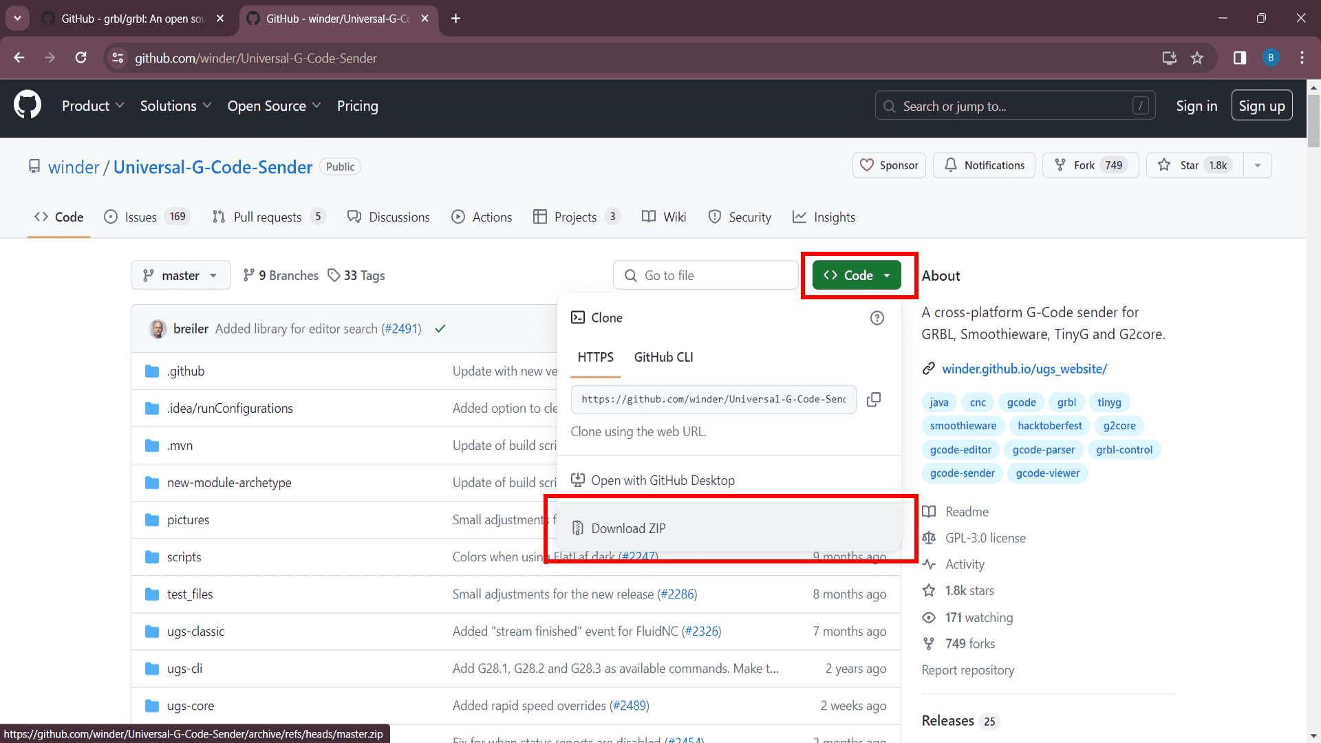
Download ZIP file by clicking on "Download ZIP" option.
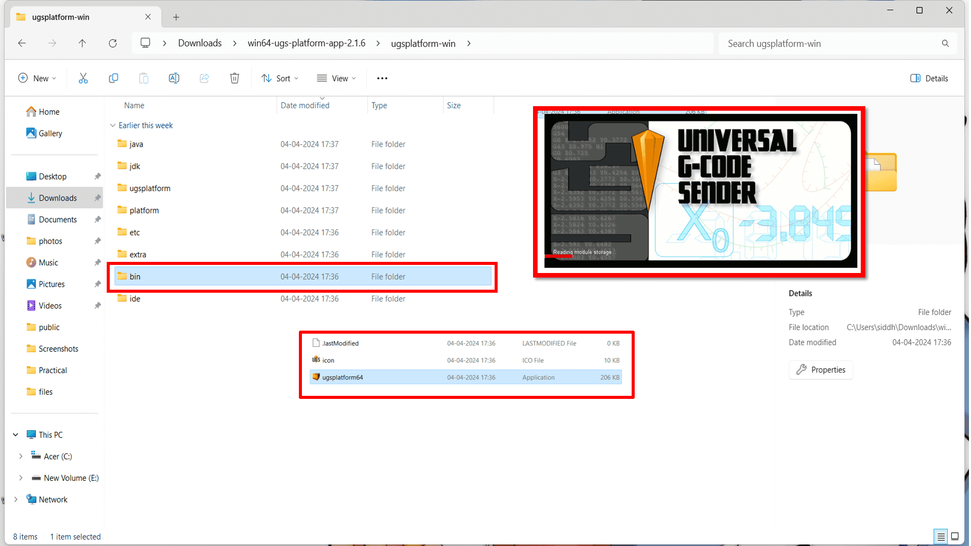
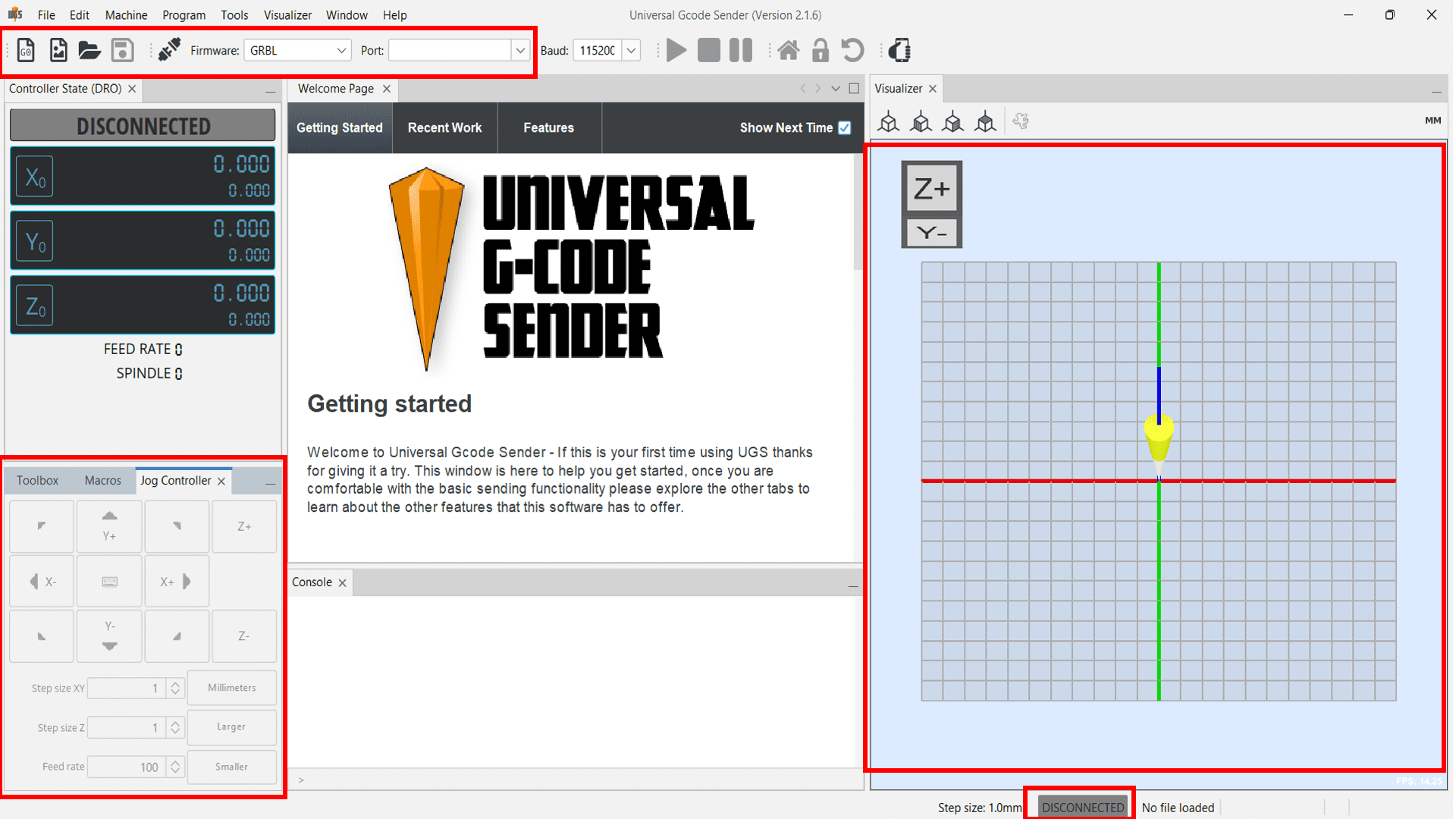
Now, extract the downloaded ZIP file and go to "bin" folder to open UGS GUI.
In this assignment, I have made documentation on-
Group Assignment
1. design a machine that includes mechanism + actuation + automation + application.
2. build the mechanical parts and operate it manually.
3. document the group project and your individual contribution.
Individual Assignment
1. document your individual contribution of the project.
My Contribution:-
We have used "grbl" firmware for our machine. GRBL is open-source software that translates G-codes into motor movements for precise control in CNC machines, ensuring accurate operation and flawless execution of your designs. The process starts with CAD software, which reads the design, and then CAM software converts it into G-codes. These G-codes are the lifeblood of your CNC machine, controlling everything from the laser module to the cutting and engraving processes.GRBL is an embedded, high-performance software designed for controlling the motion of machines that move, create, or both. Its compatibility with a range of CNC machines and superior motion control makes it a top choice for applications such as milling, laser cutting, and metal engraving.
When selecting your first CNC machine compatible with GRBL, it is important to consider factors like the type of machine, worktop size, laser power, and control software. GRBL offers numerous advantages for motion control, including superior accuracy, rapid operation, and economical cost, making it an ideal choice for controlling CNC machines with Arduino Uno.
Final testing
Firstly we have tested all the three stepper motors by inserting demo GCode to check whether it works or not. Here is the video of our first demo test-
Now, For final testing of machine, we assembled all electronic hardware components on the machine as shown in the image below. We then uploaded the GRBL code in Arduino UNO board. Important note: Remove the shield during uploading the code. And here is the ouput-
Code:
                    #include < AccelStepper.h >

                    #include < MultiStepper.h >


                    // Define the stepper motor and the pins that are connected to

                    AccelStepper stepper1(1, 54, 55); // (Typeof driver: with 2 pins, STEP, DIR)

                    AccelStepper stepper2(1, 60, 61);

                    AccelStepper stepper3(1, 46, 48);

                    #define MOTOR_X_ENABLE_PIN 38

                    #define MOTOR_Y_ENABLE_PIN 56

                    #define MOTOR_Z_ENABLE_PIN 62


                    MultiStepper steppersControl;  // Create an instance of MultiStepper


                    long gotoposition[3]; // An array to store the target positions for each stepper motor


                    void setup() {

                      // Set up the enable pins as outputs

                      pinMode(MOTOR_X_ENABLE_PIN, OUTPUT);

                      pinMode(MOTOR_Y_ENABLE_PIN, OUTPUT);

                      pinMode(MOTOR_Z_ENABLE_PIN, OUTPUT);


                      // Enable all motors initially

                      digitalWrite(MOTOR_X_ENABLE_PIN, LOW);

                      digitalWrite(MOTOR_Y_ENABLE_PIN, LOW);

                      digitalWrite(MOTOR_Z_ENABLE_PIN, LOW);


                      // Set maximum speed and acceleration for each motor

                      stepper1.setMaxSpeed(200); // Set maximum speed value for the stepper

                      stepper1.setAcceleration(500); // Set acceleration value for the stepper


                      stepper2.setMaxSpeed(200);

                      stepper2.setAcceleration(500);


                      stepper3.setMaxSpeed(200);

                      stepper3.setAcceleration(500);


                      // Adding the 3 steppers to the steppersControl instance for multi stepper control

                      steppersControl.addStepper(stepper1);

                      steppersControl.addStepper(stepper2);

                      steppersControl.addStepper(stepper3);


                    }


                    void loop() {

                      // Store the target positions in the "gotopostion" array


                      /* Set new speed and acceleration for each motor

                      stepper1.setSpeed(500); // Set a new speed value for the stepper

                      stepper2.setSpeed(500);

                      stepper3.setSpeed(500);*/


                      gotoposition[0] = 700;  // 800 steps - full rotation with quater-step resolution

                      gotoposition[1] = 700;

                      gotoposition[2] = 700;


                      steppersControl.moveTo(gotoposition);

                      steppersControl.runSpeedToPosition();


                      delay(500);

                      // scan from 0 to 180 degrees

                      gotoposition[0] = -500;  // 800 steps - full rotation with quater-step resolution

                      gotoposition[1] = -500;

                      gotoposition[2] = -500;


                      steppersControl.moveTo(gotoposition);

                      steppersControl.runSpeedToPosition();


                      delay(500);


                      // scan from 0 to 180 degrees

                      gotoposition[0] = -300;  // 800 steps - full rotation with quater-step resolution

                      gotoposition[1] = -300;

                      gotoposition[2] = -300;


                      steppersControl.moveTo(gotoposition);

                      steppersControl.runSpeedToPosition();


                      delay(500);


                      // scan from 0 to 180 degrees

                      gotoposition[0] = 300;  // 800 steps - full rotation with quater-step resolution

                      gotoposition[1] = 300;

                      gotoposition[2] = 300;


                      steppersControl.moveTo(gotoposition);

                      steppersControl.runSpeedToPosition();


                      delay(500);

                    }
Output:
We didn't get fine output at first time because misalignment of belts with pulleys. But later on we adjusted the tension of the belt. And finally we got the output.