This assignment is about documenting what we learned in Mechanical Design and Machine Design week that includes what all we did as a group in making a machine. The tasks were divided as per the processes and yet work was completed through a collaborative and concurrent approach. This documentation includes our concept, brainstorming and processes (work break-down) we followed in designing and constructing our machine.
In this assignment, we have made documentation on-
Mechanical Design
1. Design a machine that includes mechanism + actuation + automation + application
2. Build the mechanical parts and operate it manually
3. Document the group project and your individual contribution
Machine Design
1. Actuate and automate your machine
2. Document the group project and your individual contribution
Concept
We had a brainstorming session to decide on the machine, it's applications and what kind of mechanism should the machine have. We had different ideas; however, we thought of making a machine specially used for 2D drawings and pick-place mechanism. So, we started searching for the mechanism and we got different mechanism on internet. By sorting all the mechanism we have finalised to make Delta Robot.
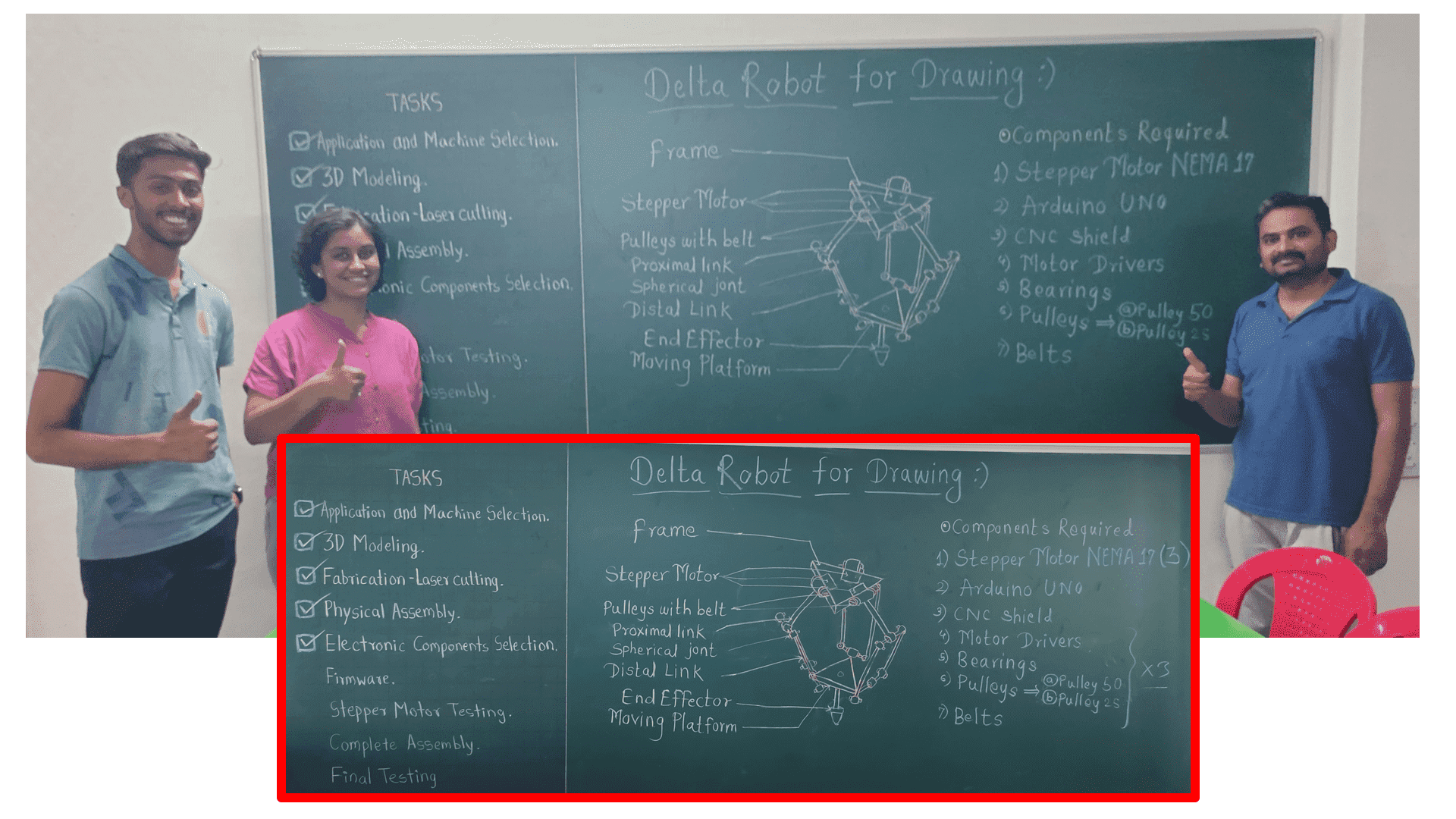
Basically, A delta robot is a parallel robot featuring three arms connected to universal joints at the base, forming a triangular configuration. This design enables high-speed and high-precision applications, often found in industries such as packaging, assembly, and pick-and-place tasks. The arms utilize parallelograms to maintain the orientation of the end effector, ensuring consistent performance throughout its workspace. Delta robots are prized for their ability to swiftly manipulate objects while maintaining accuracy, making them suitable for tasks requiring rapid and precise movements. In contrast, a Stewart platform, another type of parallel mechanism, offers different capabilities, allowing for the manipulation of its end effector's orientation through the coordinated movement of its multiple actuators.
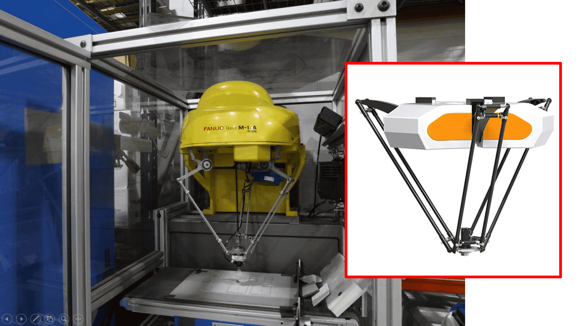
The delta robot, a type of parallel robot, comprises multiple kinematic chains linking the base to the end effector. It can be conceptualized as a spatial extension of a four-bar linkage. Fundamental to the delta robot's operation is the utilization of parallelograms, which constrain the end platform's movement exclusively to pure translation along the X, Y, or Z axes, precluding rotation. Positioned above the workspace, the robot's base houses all its actuators. Extending from the base are three articulated arms, terminating at a small triangular platform. Activation of the input links induces movement of the triangular platform along the X, Y, or Z axes. Actuation methods vary and may involve linear or rotational actuators, with or without reductions, such as direct drive systems. Click to read more.
Selection of Mechanism
Together as a group, we went through different mechanisms that can be best suited for our machine. The Delta Robot is mainly composed of three Revolute Spherical Spherical kinematic chains using mechanisms based on parallelograms restraining entirely the orientation of the travelling plate, resulting on translational motion.
Mechanical Design
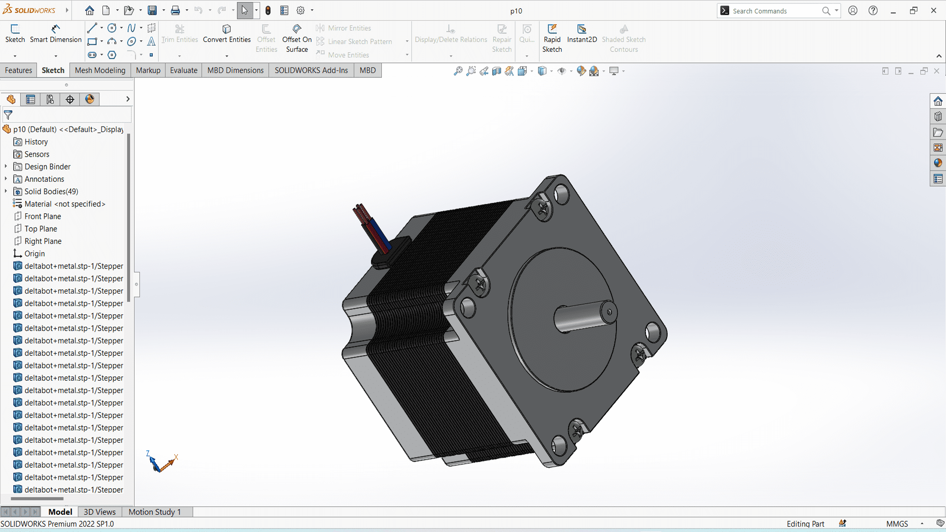
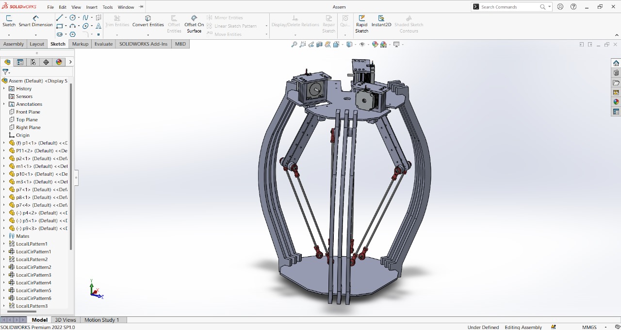
We have designed our machine and all the parts of our machine in SolidWorks. Following are the snapshots of our design.
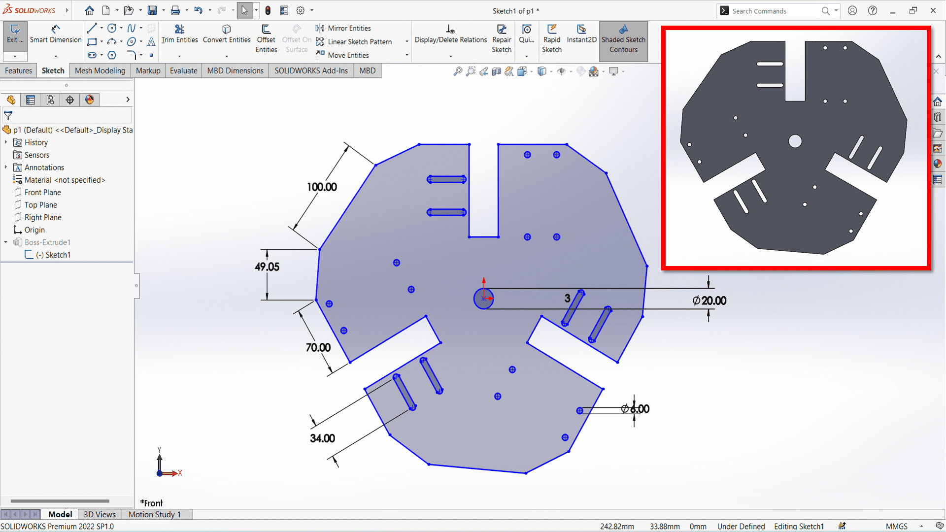
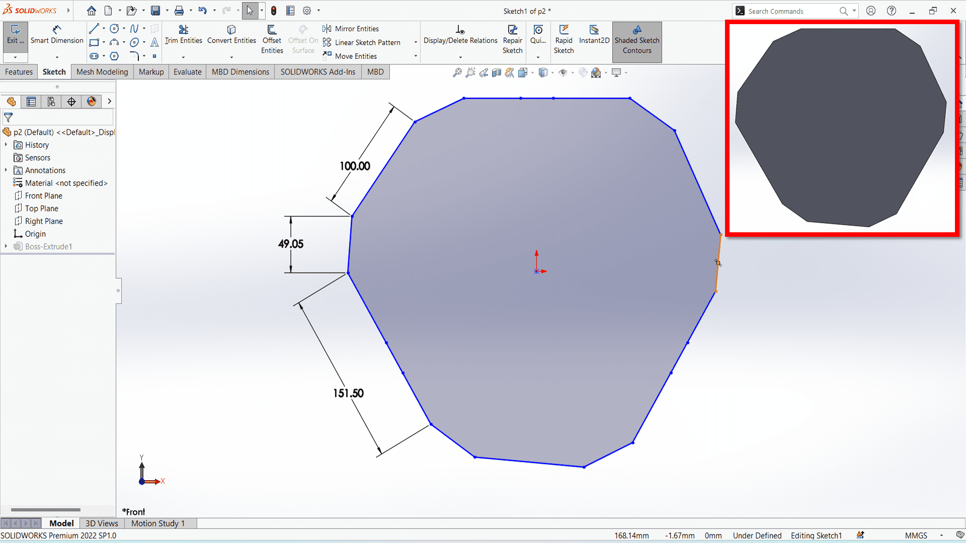
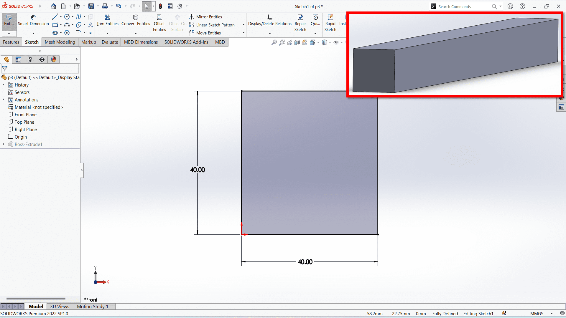
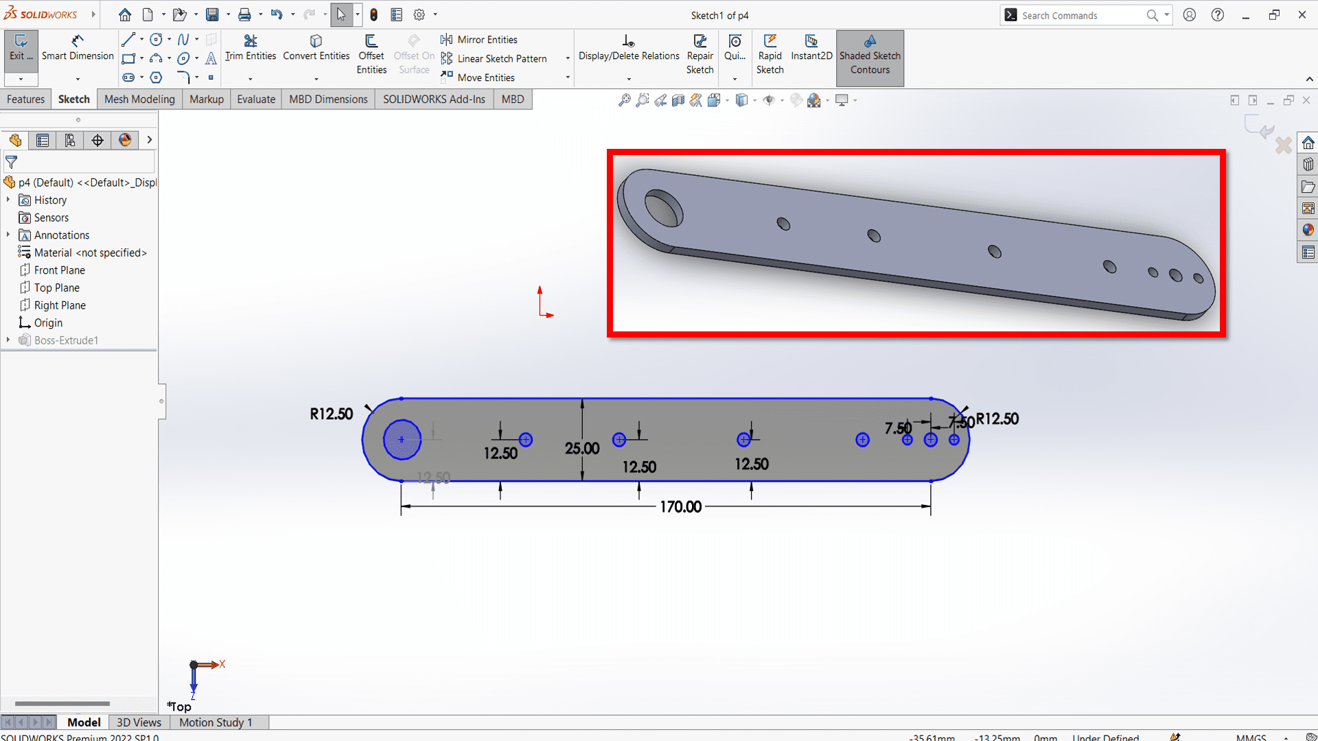
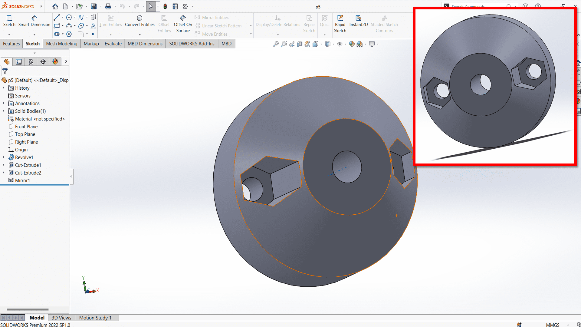
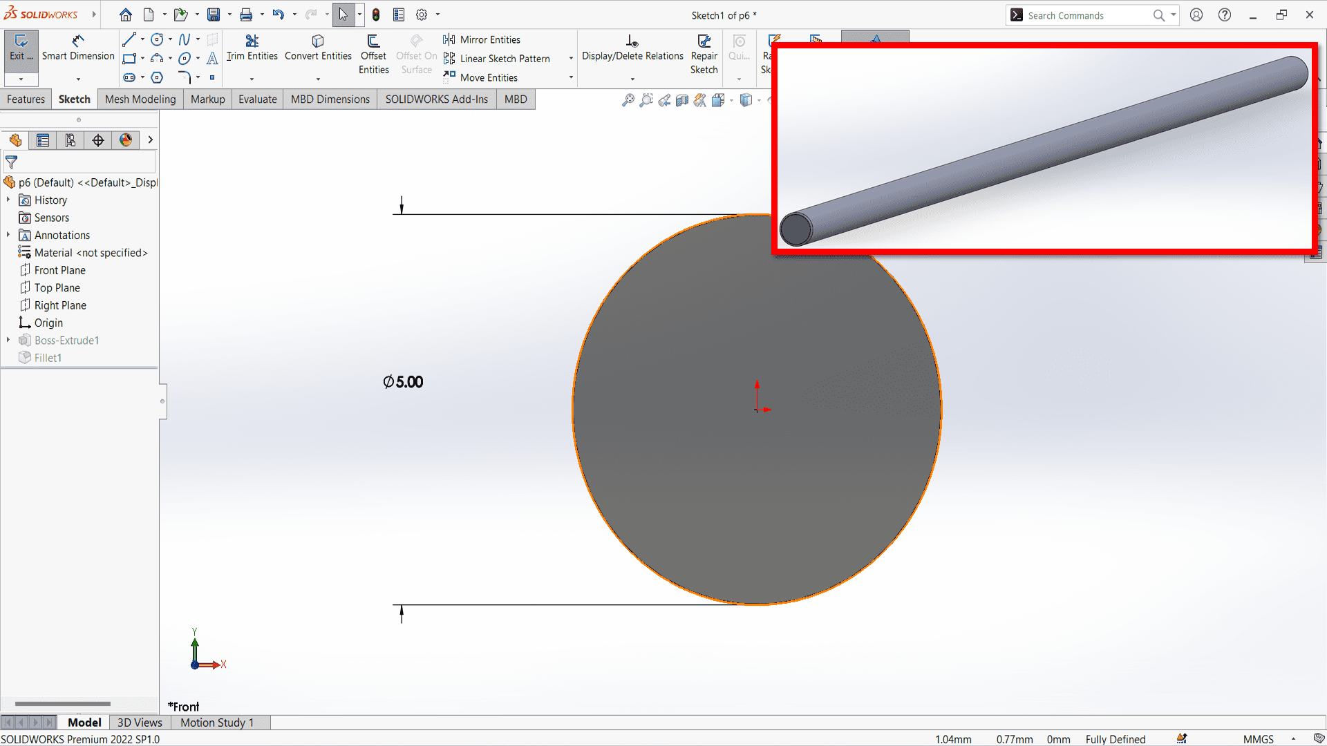

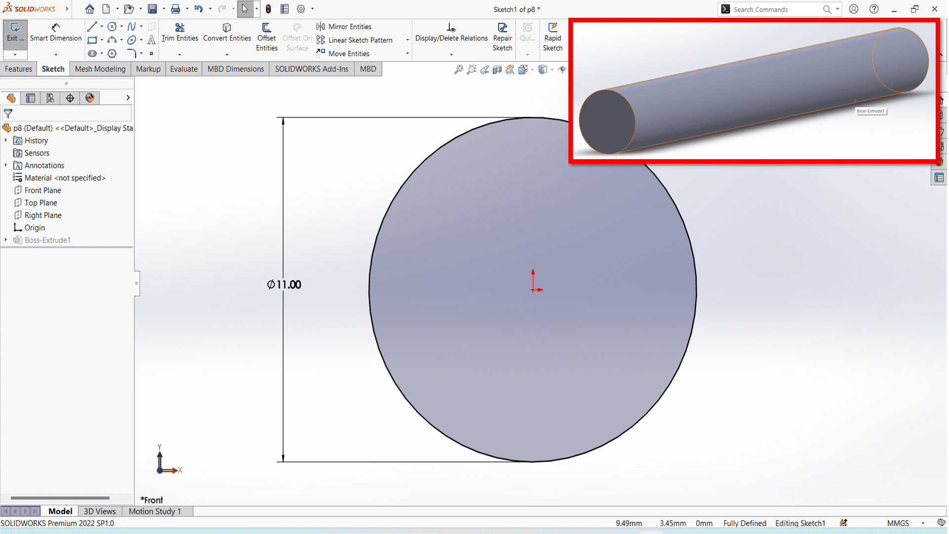
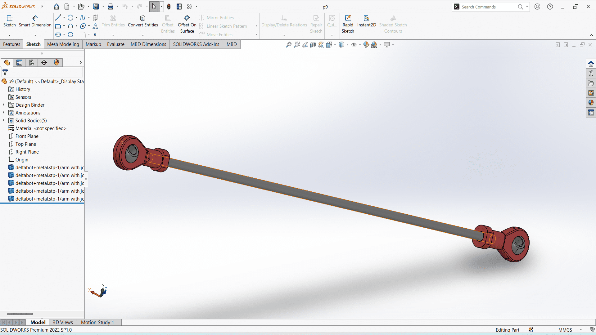

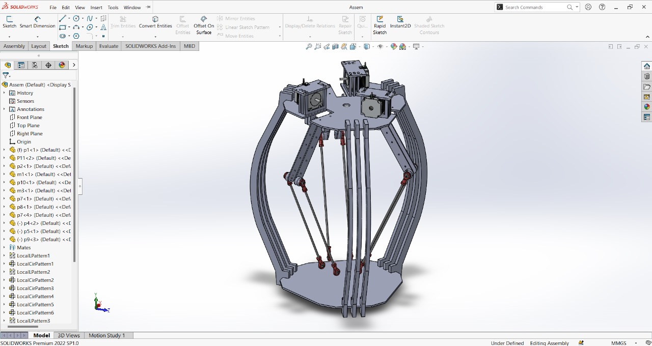
Following is the assembly of the machine in SolidWorks.
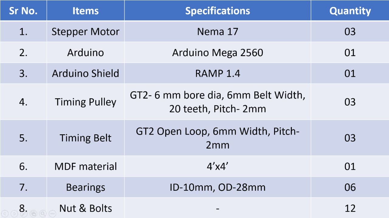
Bill of Material
Below is our engineering and manufacturing Bill of Material of our entire machine. We did not include wires and power supply accessories in to the BOM.
Fabrication
1. Laser Cutting
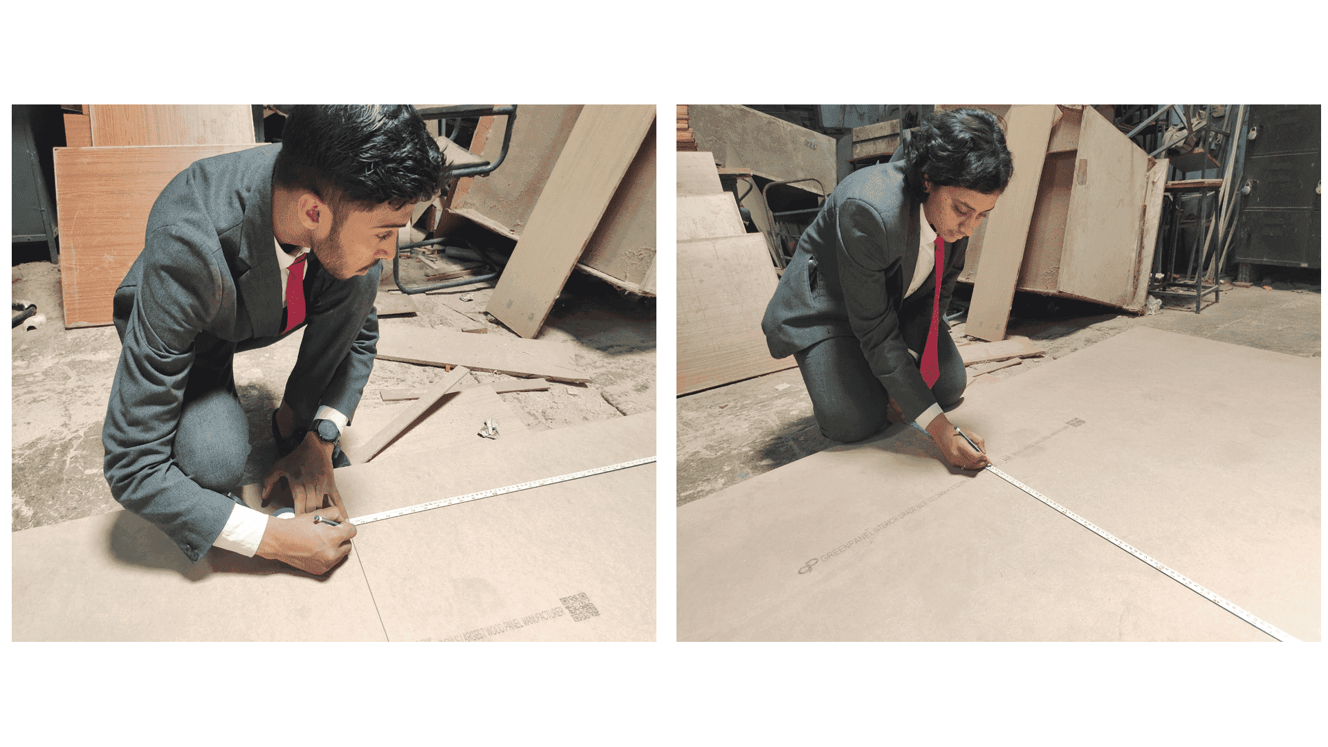
To make a frame of our machine, we decided to use laser cutter. We have taken 6mm MDF material from our college's workshop store.
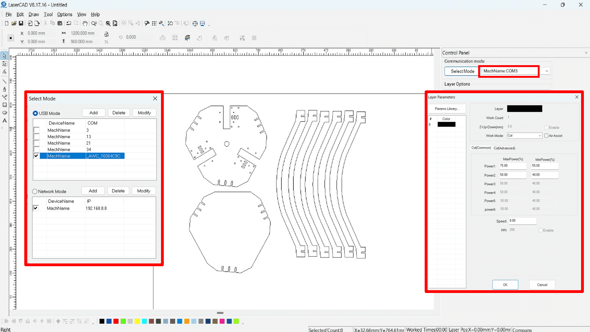
Then, we have inserted our designed part into Laser CAD software to convert .dxf file into GCode format which helps laser cutter to cut respective uploaded design. Here are some snapshots.

Here, we have uploaded .dxf file into laser CAD by clicking "ctrl+i" option or directly importing file.

Here are some snapshots during laser cutting.
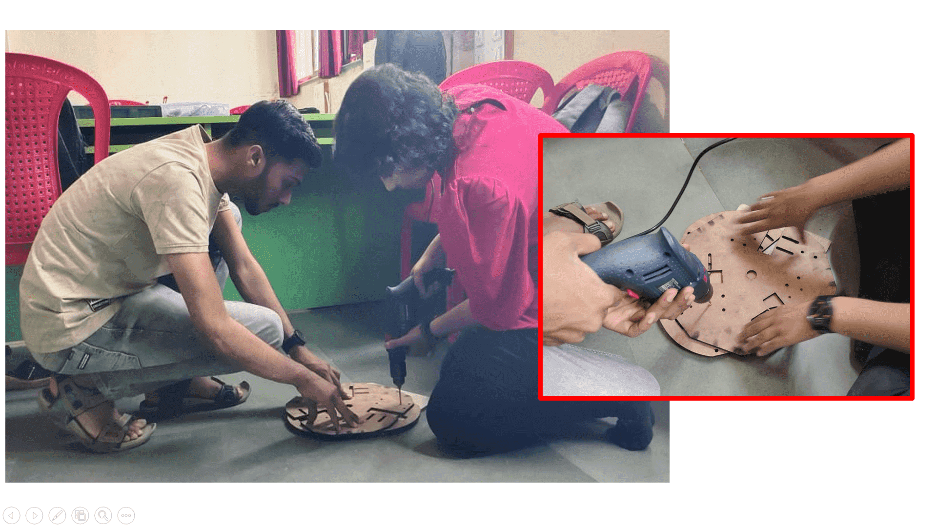
2. Drilling
We needed to drill some holes of top frame because of some kerf calculation changes. So, we used drilling machine to drill holes.
Assembly
Once all the parts were in place (either purchased, laser cut or from our lab inventory), we started to assemble the machine. Following is a picture of all the material in place.

Electronics
A. Selection of electronic components
Here is the list of components which we have finalised-
1) Stepper motor
2) Stepper motor drivers
3) Driver shield
4) Control board
5) External power supply
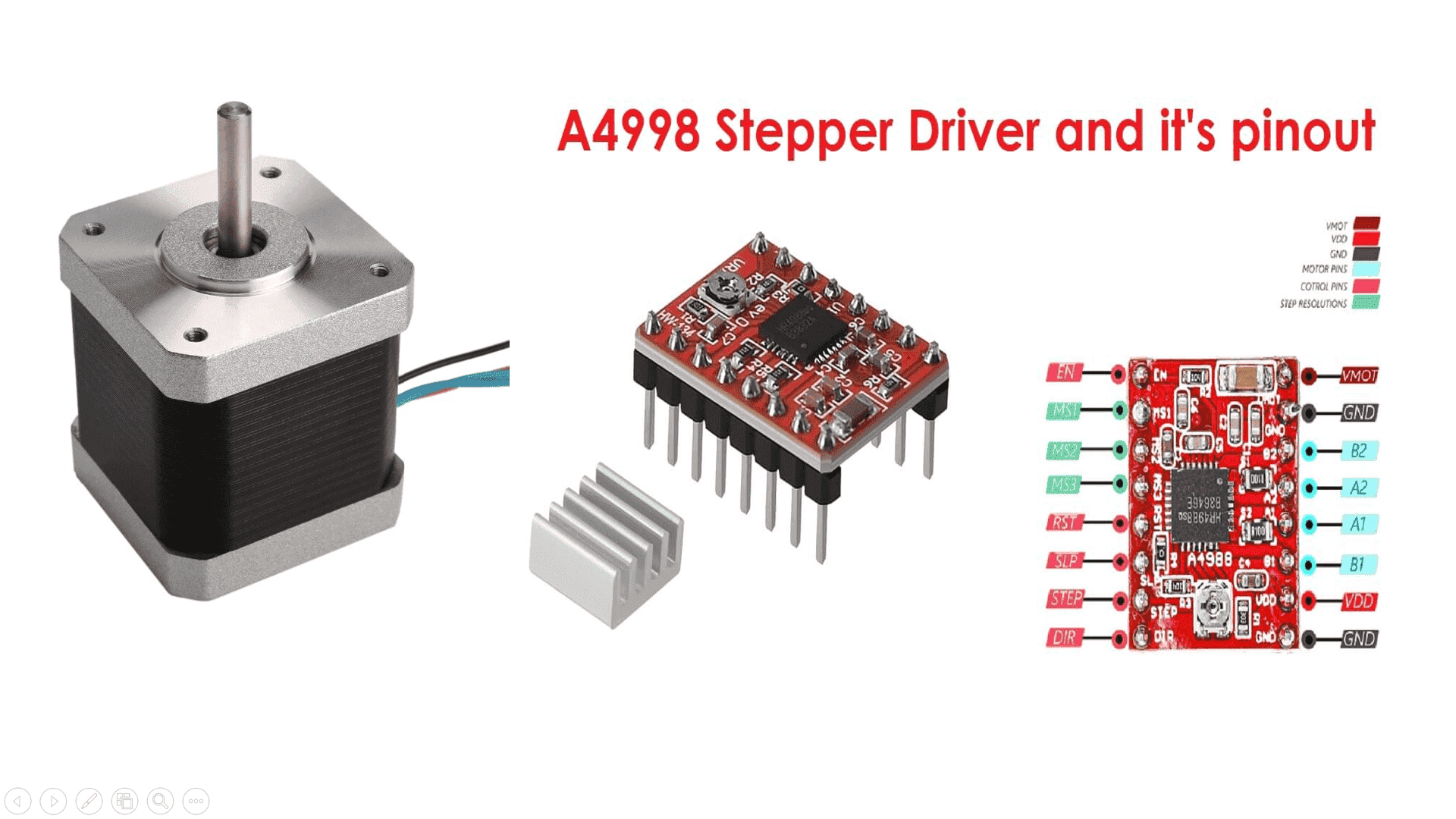
Selecting the stepper motors and stepper drivers-
Based on the requirements of the mechanical design of the machine, we selected Nema 17 stepper motor with 4.7 kg-cm torque to drive the machine axis. We selected three motors for running XYZ axes.
For running the stepper motors, we required stepper drivers. For, which we had multiple options. However, considering the driver configuration availability in GRBL firmware and the inventory we had in our lab, we went with A4988 as a motor driver.
Selecting the CNC stepper driver shield and controller board-
There are so many types of CNC stepper driver shields available, out of, which we have selected Arduino CNC V3 shield connect with Arduino UNO board. The Arduino CNC shield, when paired with an Arduino Uno board and running the GRBL firmware, provides a compact and accessible solution for controlling CNC machinery. This setup allows for seamless integration of stepper motor drivers, limit switches, and other essential components, facilitating precise and efficient CNC operations. By uploading the GRBL firmware onto the Arduino Uno, users can harness the power of G-code commands to execute a wide range of machining tasks with accuracy and reliability.

Selecting the power supply
As per the requirement of current consumption and voltage requirement for electric components for our machine, we chose 12V 5A power supply for powering up the machine.
Testing of electronic components-
1. Testing stepper motor and stepper motor drivers
We wanted to test the stepper motor before setting up our electronic assembly for our machine. As we are going to use GRBL firmware and it is not configured yet, so we decided to test the stepper motor first. We started with testing individual stepper motors for, which we reffered Arduino and stepper motor configurations. We tested all the three motors and drivers, they were working fine.
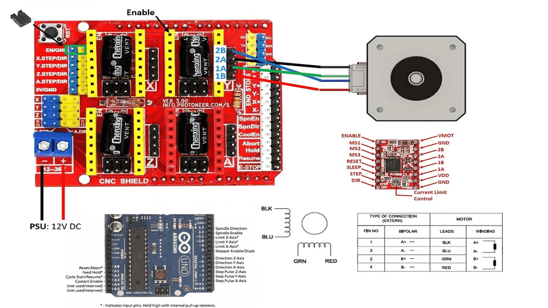
2. Testing stepper motors with Arduino CNC Shield V3
In the process of testing a stepper motor with an Arduino Uno and an Arduino CNC Shield V3, it's imperative to ensure a seamless connection between the components. Begin by affixing the CNC shield securely onto the Arduino Uno board. Once properly mounted, establish the physical link between the stepper motor and one of the available stepper motor driver sockets on the CNC shield. Ensure correct wiring by connecting the motor wires to the designated pins on the driver, typically labeled as A+, A-, B+, and B-. Following the hardware setup, upload a test sketch to the Arduino Uno using the Arduino IDE. This sketch should utilize the Arduino Stepper library to control the motor's movement. Set parameters such as the number of steps per revolution and the desired speed of rotation within the sketch. Execute the test by running the uploaded sketch, observing the stepper motor's behavior as it undergoes programmed movements. This testing phase allows for the verification of proper functionality and serves as a crucial step in preparing the system for subsequent CNC operations.
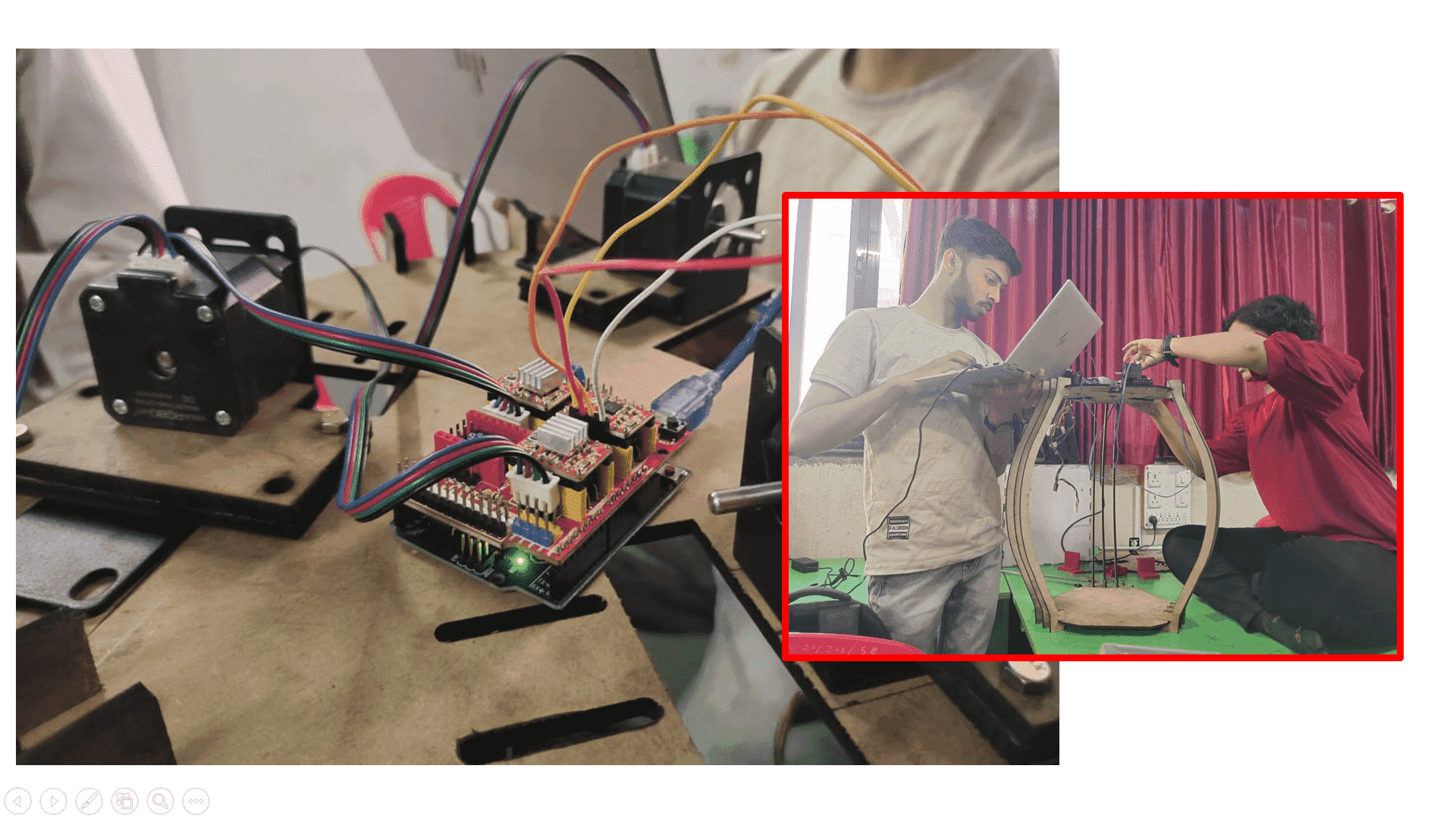
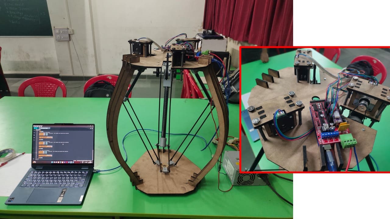
3. Connections and routing on the machine For final testing of machine, we assembled all electronic hardware components on the machine as shown in the image below. We then uploaded the GRBL code in Arduino UNO board. Important note: Remove the shield during uploading the code.
B. Firmware and Interfacing
We have used "grbl" firmware for our machine. GRBL is open-source software that translates G-codes into motor movements for precise control in CNC machines, ensuring accurate operation and flawless execution of your designs. The process starts with CAD software, which reads the design, and then CAM software converts it into G-codes. These G-codes are the lifeblood of your CNC machine, controlling everything from the laser module to the cutting and engraving processes.GRBL is an embedded, high-performance software designed for controlling the motion of machines that move, create, or both. Its compatibility with a range of CNC machines and superior motion control makes it a top choice for applications such as milling, laser cutting, and metal engraving.
When selecting your first CNC machine compatible with GRBL, it is important to consider factors like the type of machine, worktop size, laser power, and control software. GRBL offers numerous advantages for motion control, including superior accuracy, rapid operation, and economical cost, making it an ideal choice for controlling CNC machines with Arduino Uno.
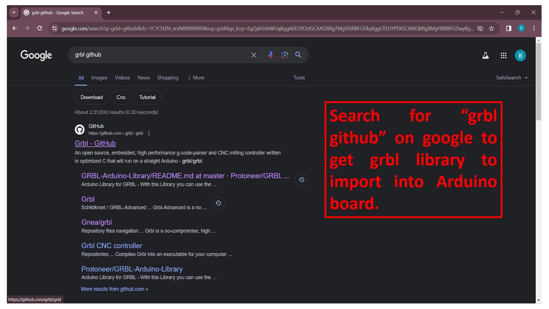
Firstly, search "grbl Github" on google or click on 👉 grbl github to get grbl file to import in Arduino board for machine work.
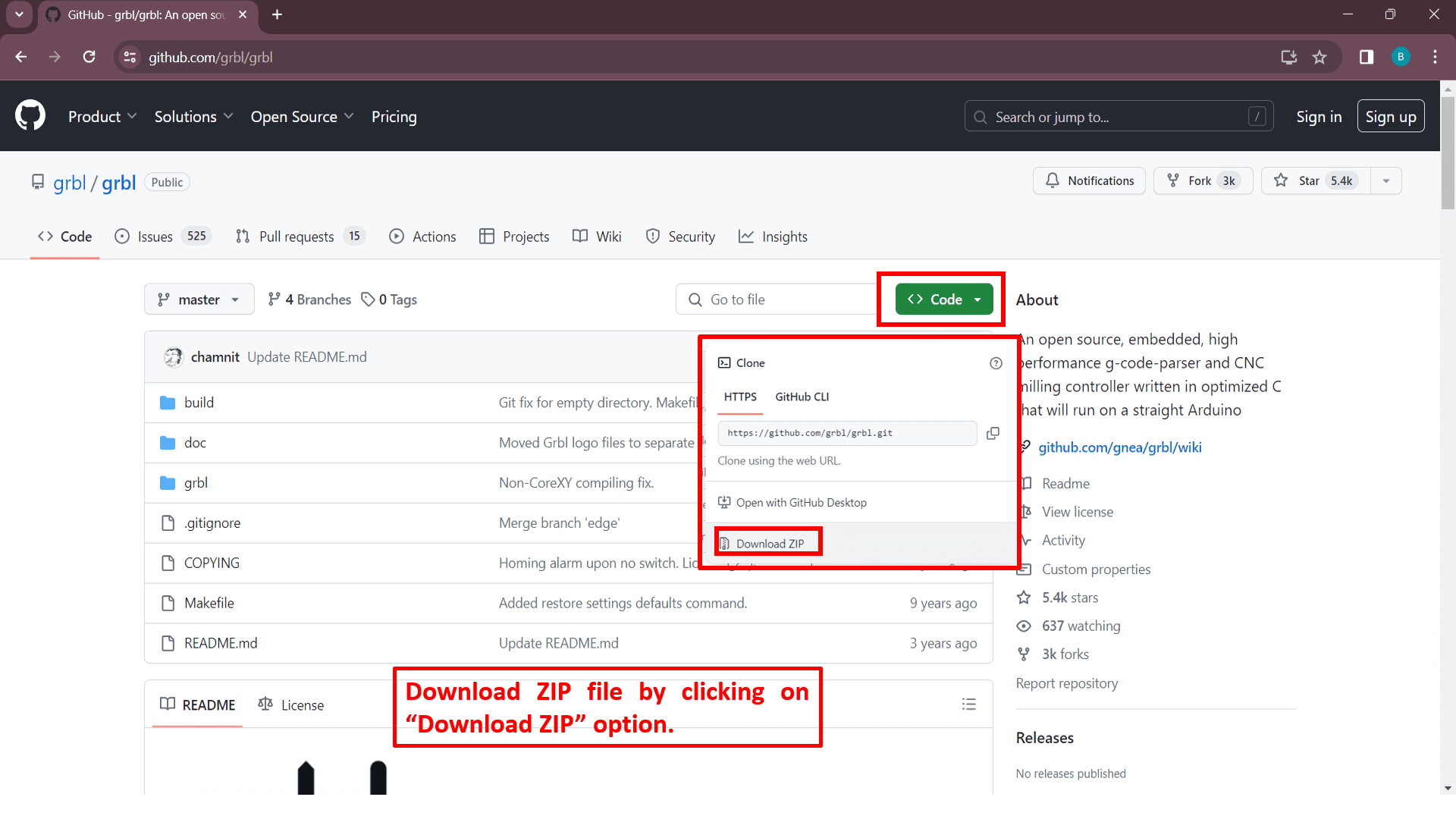
Now, download zip file by clicking on "Download ZIP" option which is situated in the drop down list of "Code" button.
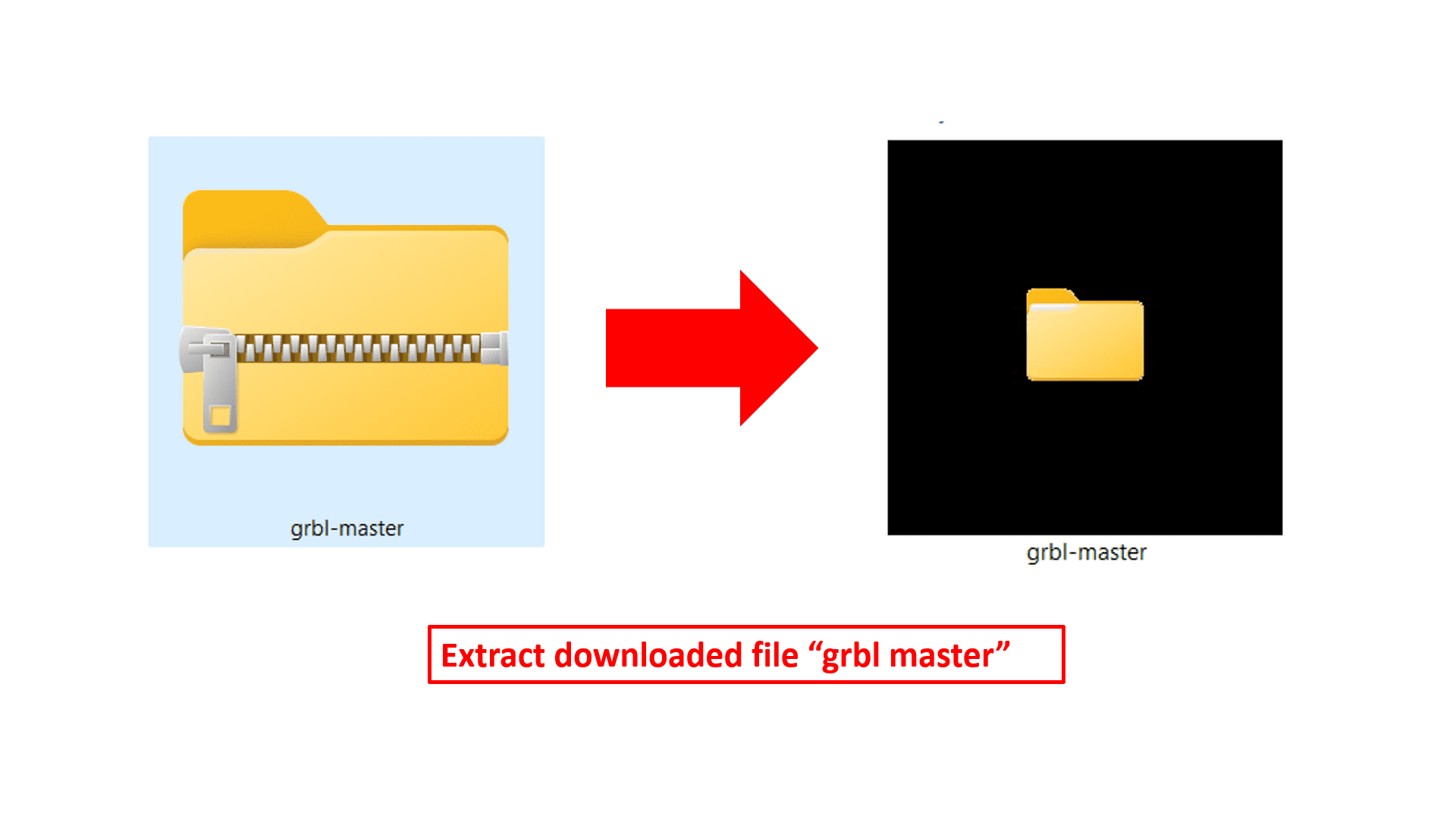
Extract the downloaded ZIP file by clicking on "Extract All" option by clicking on right click.
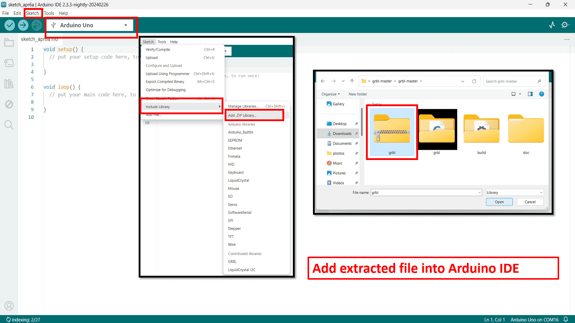
Open Arduino IDE and firstly select board type-Arduino UNO. Then, add "grbl" ZIP file which we have taken from extracted "grbl master" file by going to include library option situated in "Sketch" option.
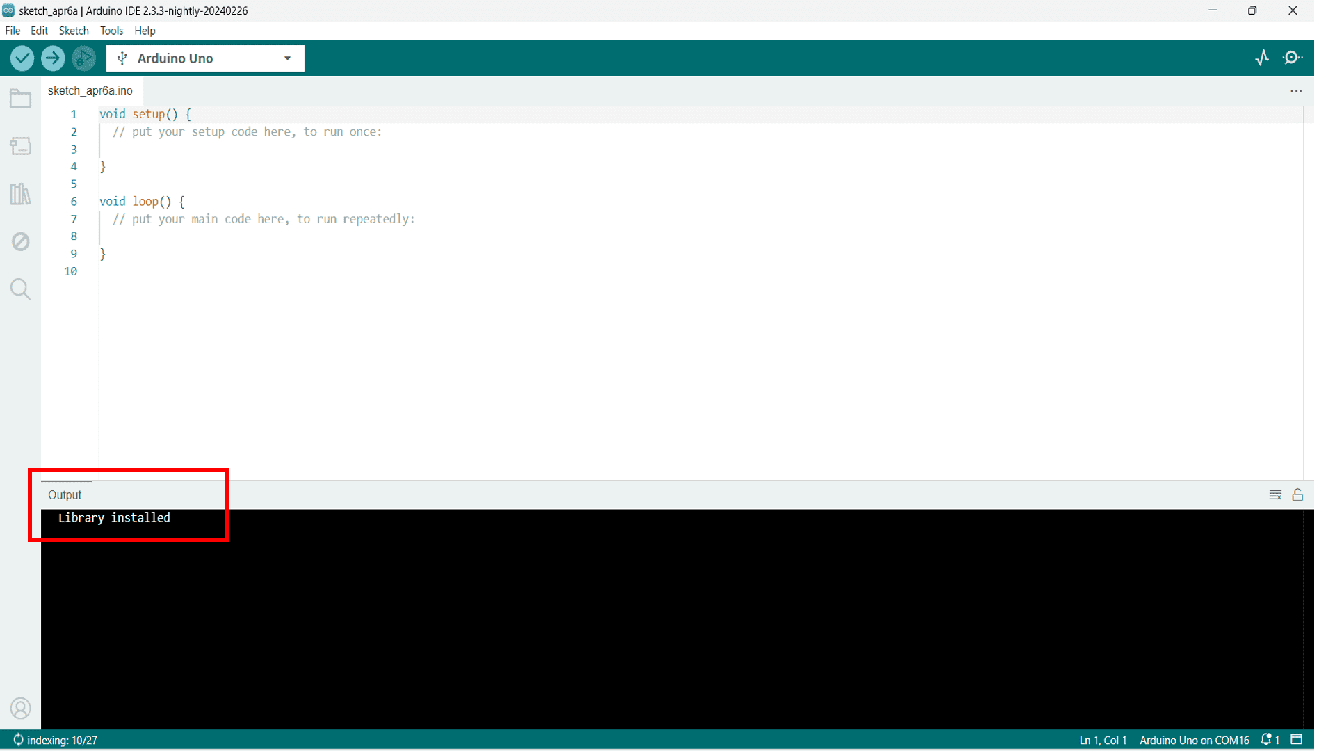
Now, the library is installed into Arduino IDE.
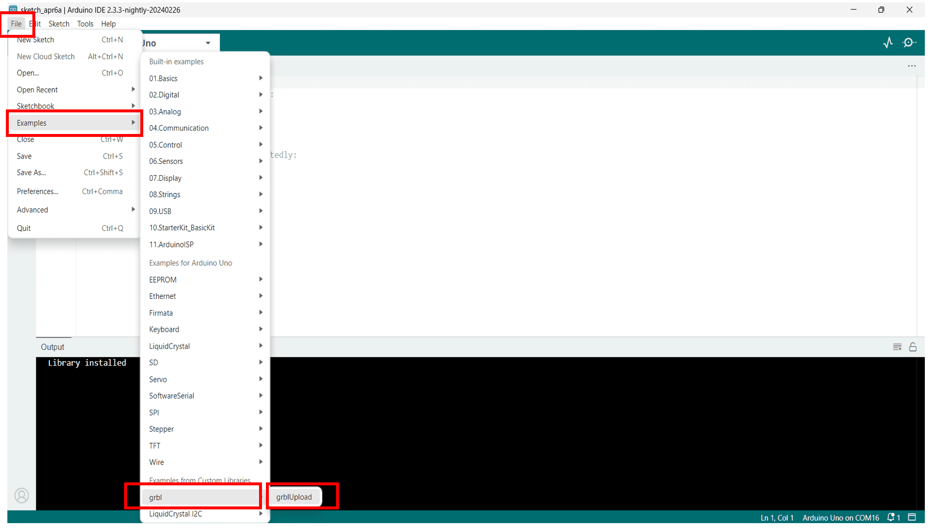
Go to "Examples" option located in the dropdown list of "File" option and upload installed library in IDE.
Here is the library of grbl firmware.
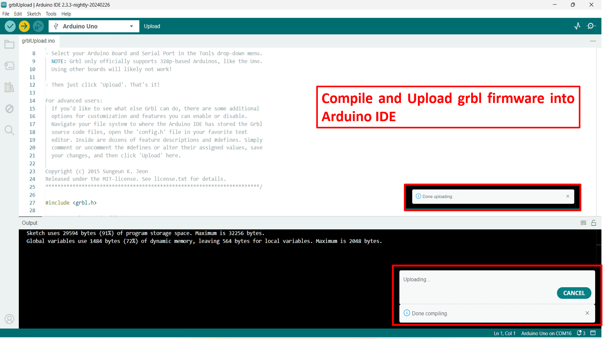
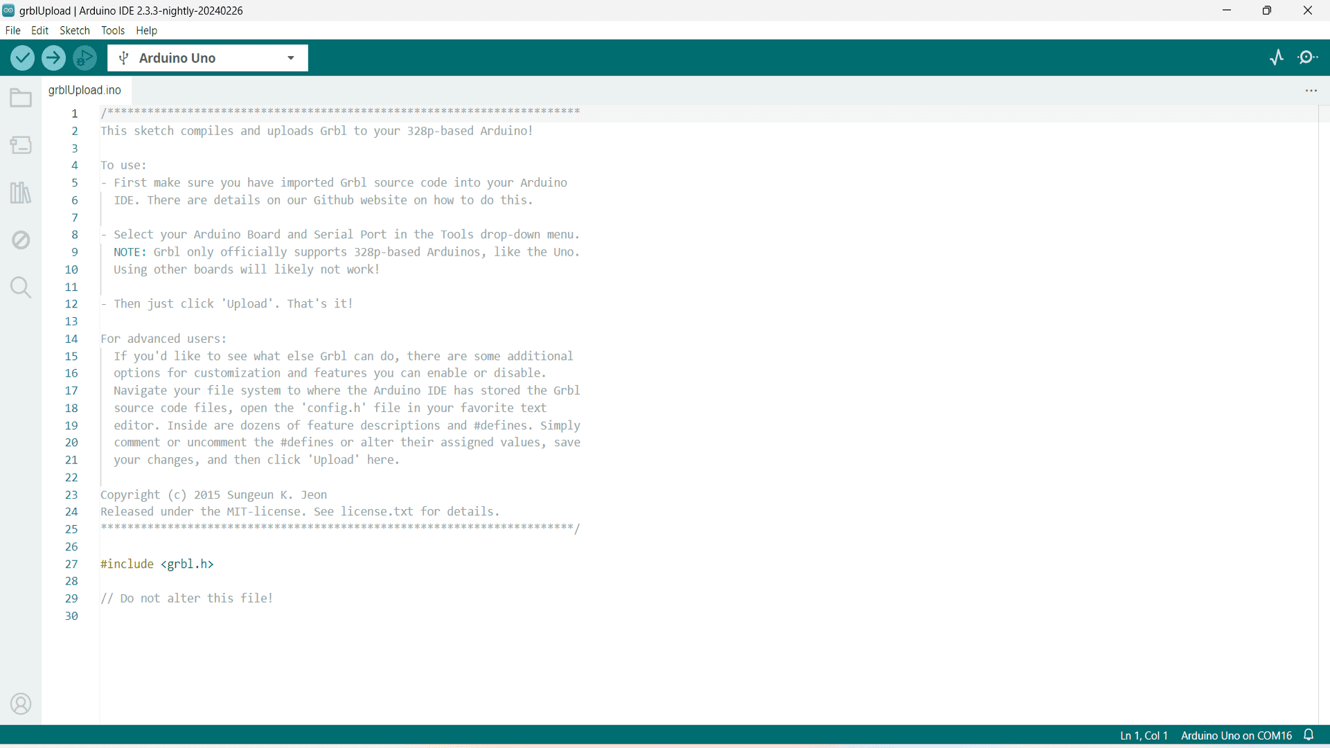
Now, Compile the code and upload it into Arduino board. Finally the firmware uploading is done.
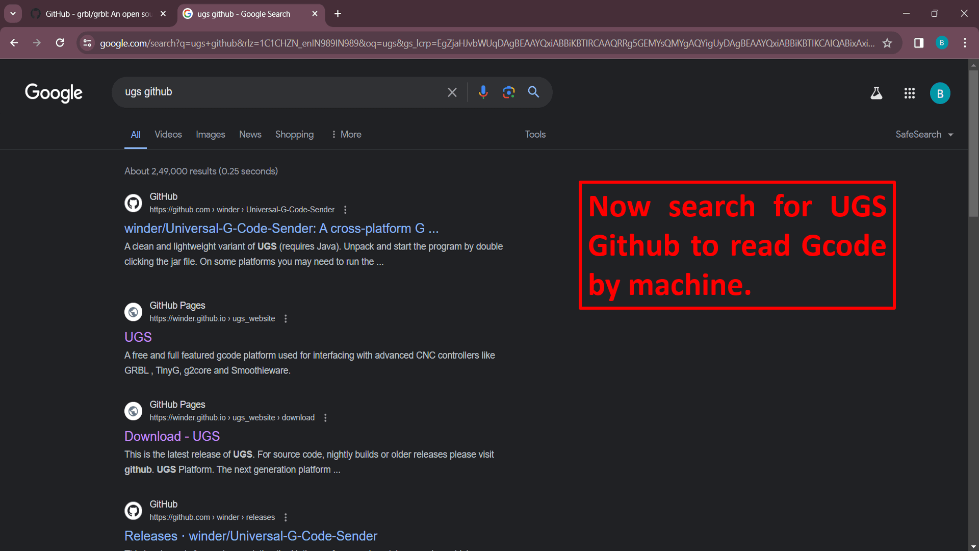
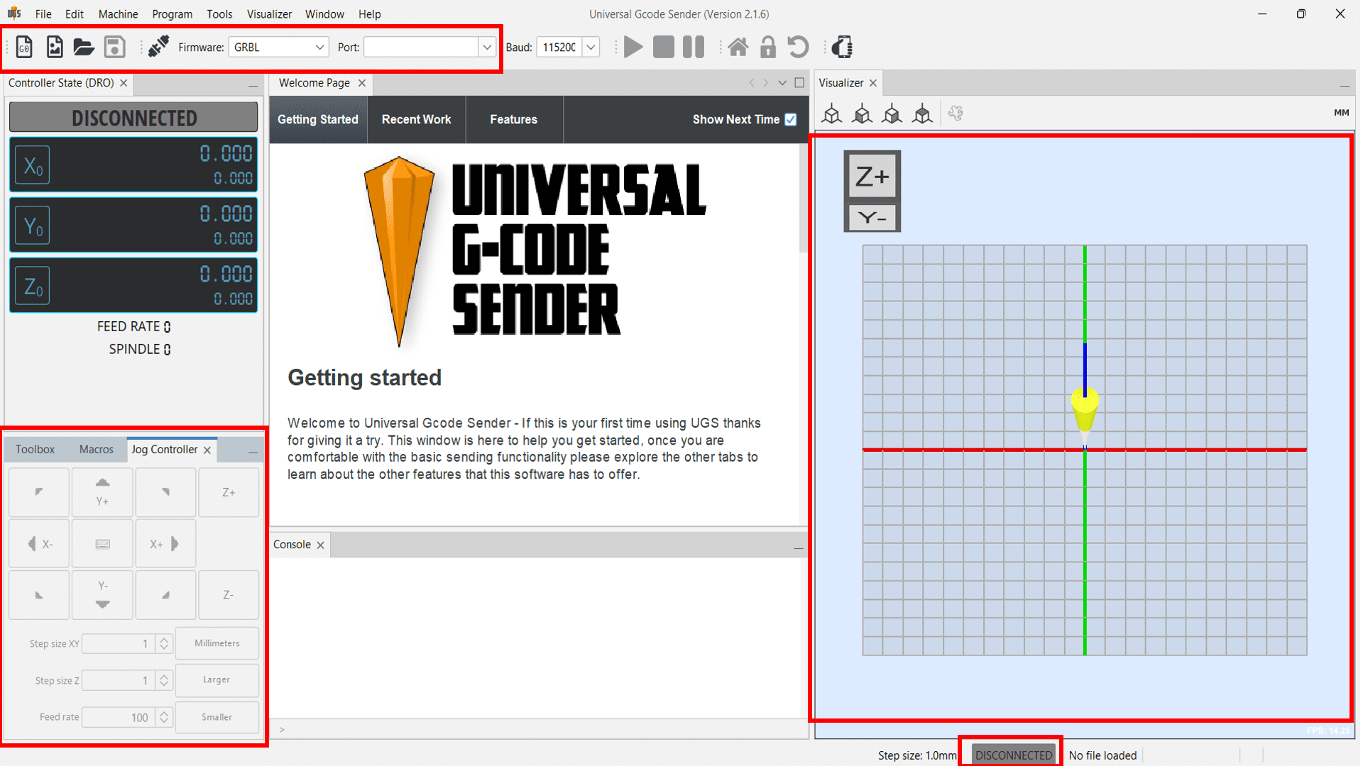
Now, to operate our machine we needed Graphical User Interface. So, we decided to use UGS-Universal GCode Sender. To download this open source GUI, again search "ugs github" on google.
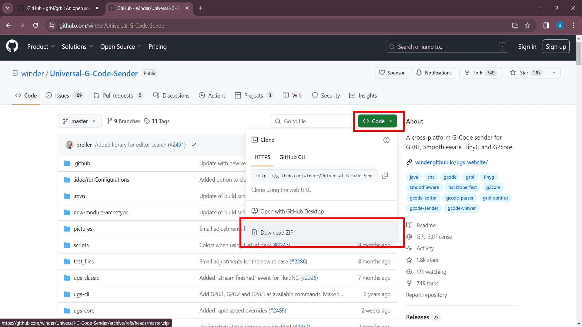
Download ZIP file by clicking on "Download ZIP" option.
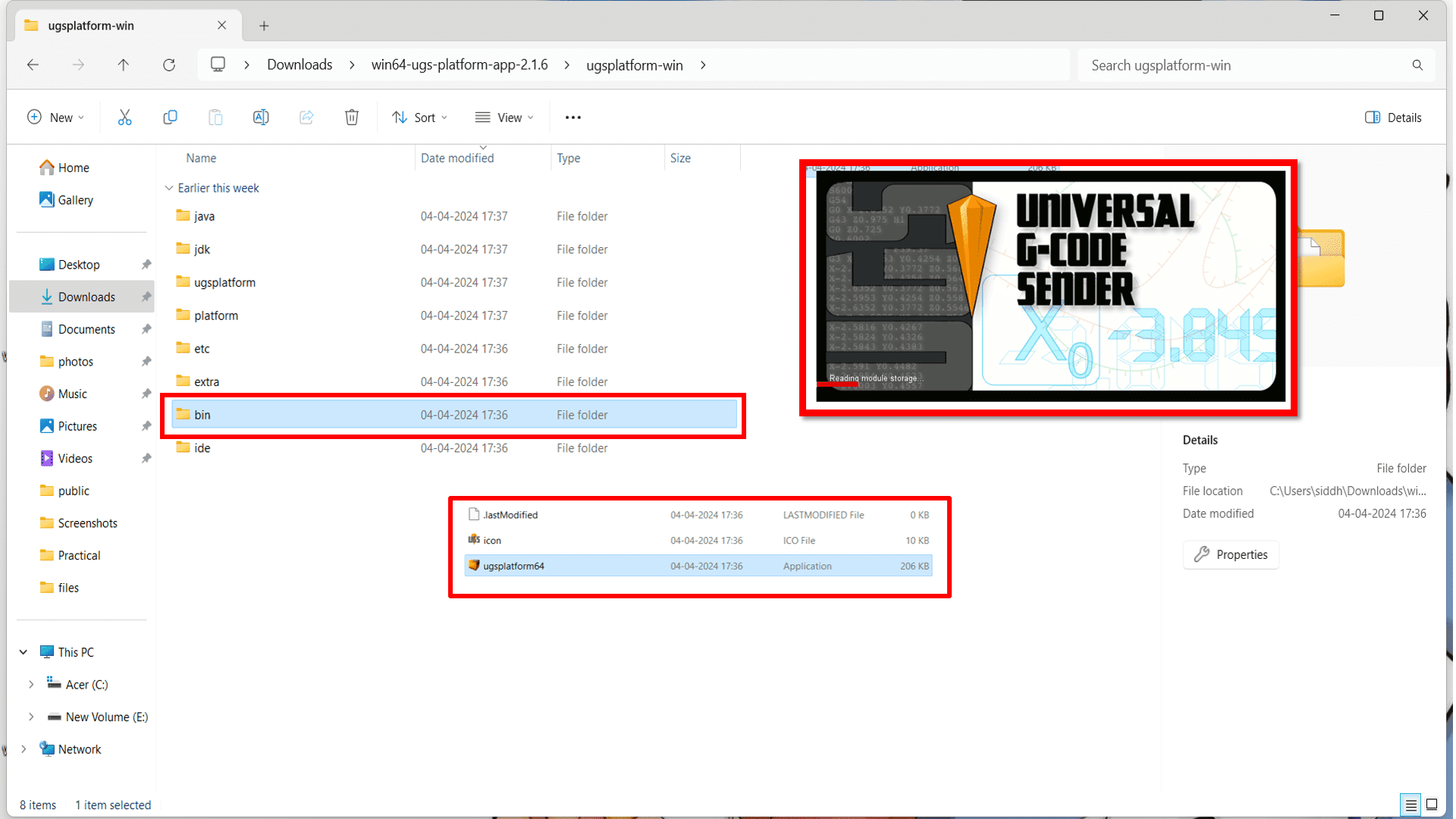
Now, extract the downloaded ZIP file and go to "bin" folder to open UGS GUI.
Final testing
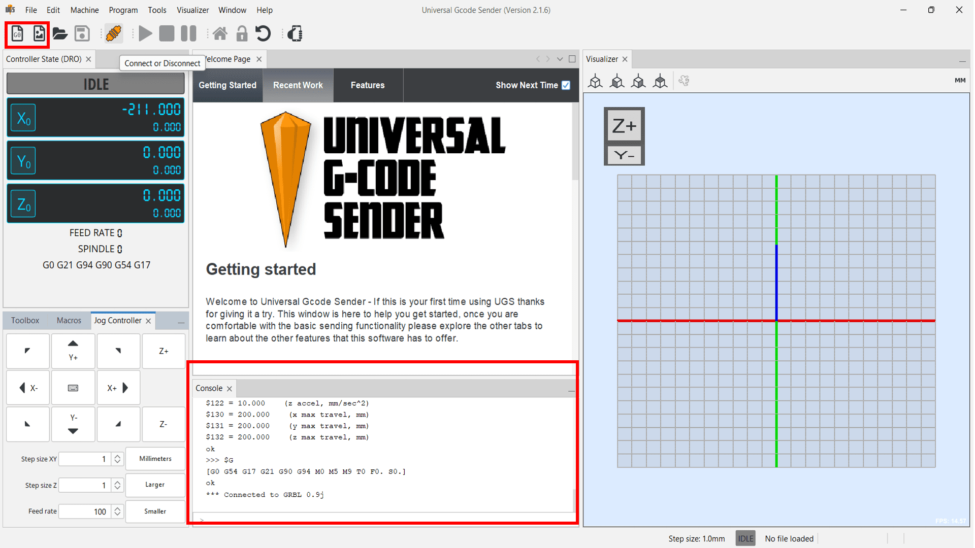
Firstly we have tested all the three stepper motors by inserting demo GCode to check whether it works or not. Here is the video of our first demo test-
Now, For final testing of machine, we assembled all electronic hardware components on the machine as shown in the image below. We then uploaded the GRBL code in Arduino UNO board. Important note: Remove the shield during uploading the code. And here is the ouput-
Code:
            #include < AccelStepper.h >

            #include < MultiStepper.h >


            // Define the stepper motor and the pins that are connected to

            AccelStepper stepper1(1, 54, 55); // (Typeof driver: with 2 pins, STEP, DIR)

            AccelStepper stepper2(1, 60, 61);

            AccelStepper stepper3(1, 46, 48);

            #define MOTOR_X_ENABLE_PIN 38

            #define MOTOR_Y_ENABLE_PIN 56

            #define MOTOR_Z_ENABLE_PIN 62


            MultiStepper steppersControl;  // Create an instance of MultiStepper


            long gotoposition[3]; // An array to store the target positions for each stepper motor


            void setup() {

              // Set up the enable pins as outputs

              pinMode(MOTOR_X_ENABLE_PIN, OUTPUT);

              pinMode(MOTOR_Y_ENABLE_PIN, OUTPUT);

              pinMode(MOTOR_Z_ENABLE_PIN, OUTPUT);


              // Enable all motors initially

              digitalWrite(MOTOR_X_ENABLE_PIN, LOW);

              digitalWrite(MOTOR_Y_ENABLE_PIN, LOW);

              digitalWrite(MOTOR_Z_ENABLE_PIN, LOW);


              // Set maximum speed and acceleration for each motor

              stepper1.setMaxSpeed(200); // Set maximum speed value for the stepper

              stepper1.setAcceleration(500); // Set acceleration value for the stepper


              stepper2.setMaxSpeed(200);

              stepper2.setAcceleration(500);


              stepper3.setMaxSpeed(200);

              stepper3.setAcceleration(500);


              // Adding the 3 steppers to the steppersControl instance for multi stepper control

              steppersControl.addStepper(stepper1);

              steppersControl.addStepper(stepper2);

              steppersControl.addStepper(stepper3);


            }


            void loop() {

              // Store the target positions in the "gotopostion" array


              /* Set new speed and acceleration for each motor

              stepper1.setSpeed(500); // Set a new speed value for the stepper

              stepper2.setSpeed(500);

              stepper3.setSpeed(500);*/


              gotoposition[0] = 700;  // 800 steps - full rotation with quater-step resolution

              gotoposition[1] = 700;

              gotoposition[2] = 700;


              steppersControl.moveTo(gotoposition);

              steppersControl.runSpeedToPosition();


              delay(500);

              // scan from 0 to 180 degrees

              gotoposition[0] = -500;  // 800 steps - full rotation with quater-step resolution

              gotoposition[1] = -500;

              gotoposition[2] = -500;


              steppersControl.moveTo(gotoposition);

              steppersControl.runSpeedToPosition();


              delay(500);


              // scan from 0 to 180 degrees

              gotoposition[0] = -300;  // 800 steps - full rotation with quater-step resolution

              gotoposition[1] = -300;

              gotoposition[2] = -300;


              steppersControl.moveTo(gotoposition);

              steppersControl.runSpeedToPosition();


              delay(500);


              // scan from 0 to 180 degrees

              gotoposition[0] = 300;  // 800 steps - full rotation with quater-step resolution

              gotoposition[1] = 300;

              gotoposition[2] = 300;


              steppersControl.moveTo(gotoposition);

              steppersControl.runSpeedToPosition();


              delay(500);

            }
Output:
We didn't get fine output at first time because misalignment of belts with pulleys. But later on we adjusted the tension of the belt. And finally we got the output.
Some Important G and M codes-
Machine codes like G code and M codes are used to control a cnc machine through a CLI. In pronterface we could individually send G code and M codes to setup the homming and perform other functionality.
1. G28 - Homing position
2. G90 - Absolute positioning
3. M1 - Sleep
4. M2 - Program End
5. M12 - Enable stepper motors
6. M30 - Program Stop
7. M84 - Motors Off
8. M114 - Get Current Values
9. M428 - Set an arbitary Value
10. M500 - Stores the set value
Some important points(learning) that we listed for electronics part-
1. Know the board that you are using in this case it is an Arduino UNO and Arduino CNC shield V3. Note:- Do check the support list on GRBL about the hardware that you are going to choose.
2. Compile and upload the code on to Arduino UNO board.
3. After uploading the firmware, check the movement of the motor. Check the stepping. Mount the motor to the assembly and check the XYZ movements.
Learning Outcomes from this assignment
1. Selection of electronic components based on application
2. Used firmware for machine operation.