Output Devices:-
What is output device? The name itself give an idea that the device which gives an output called as output device. An output device is a hardware component that takes information from a computer and presents it to the user in a way they can understand. This can be through a screen that shows images and text, speakers that play sounds, or a printer that makes physical copies of documents. Output devices are essential because they let us see, hear, and use the information that the computer processes.
Group Assignment
Click here to see group assignment in detail.
Individual Assignmment
In individual assignment, I designed PCB board which includes output devices - Buzzer, LCD and RGB led.
1) Buzzer
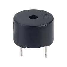
A buzzer is a small, simple output device that produces sound. It converts electrical signals into audible tones, making it an essential component in many electronic devices for alerting or signaling users. Buzzers are commonly used in alarms, timers, and various types of notification systems to provide audio feedback or warnings. They can emit different types of sounds, such as beeps, chirps, or continuous tones, depending on the design and application. Buzzers are valued for their simplicity, reliability, and effectiveness in drawing attention to a specific event or condition. Buzzer has 2 pins, one is digital and another is ground.
2) LCD
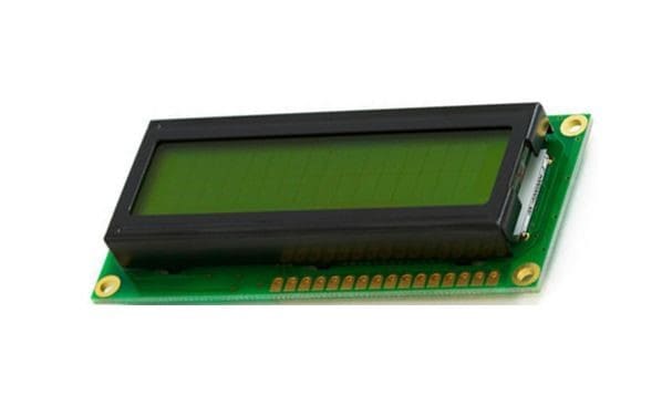
A 16 by 2 LCD (Liquid Crystal Display) is a small screen that shows text. It can display up to 16 characters across and has 2 rows of text, making a total of 32 characters visible at once. These displays are handy for projects where you need to show words or numbers clearly, like in digital clocks or small gadgets. They often have a backlight for easy viewing in different lighting. You can connect them to devices like Arduino or Raspberry Pi to control what shows up on the screen, making them useful for DIY electronics and learning projects.
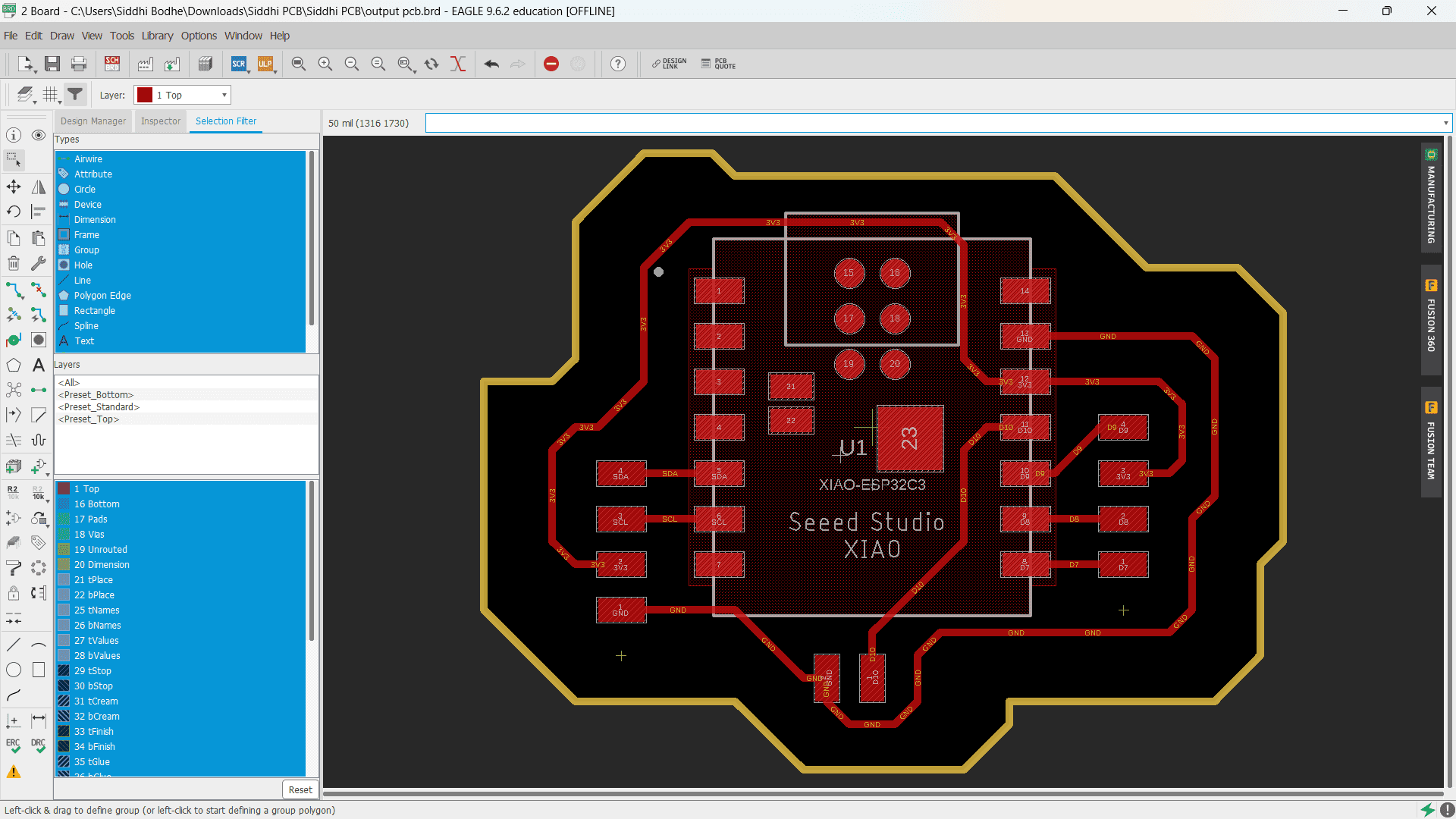
Here, I designed PCB Schematic in AutoDesk Eagle Software for PCB of output devices.
Here is the final design of PCB board for output devices.
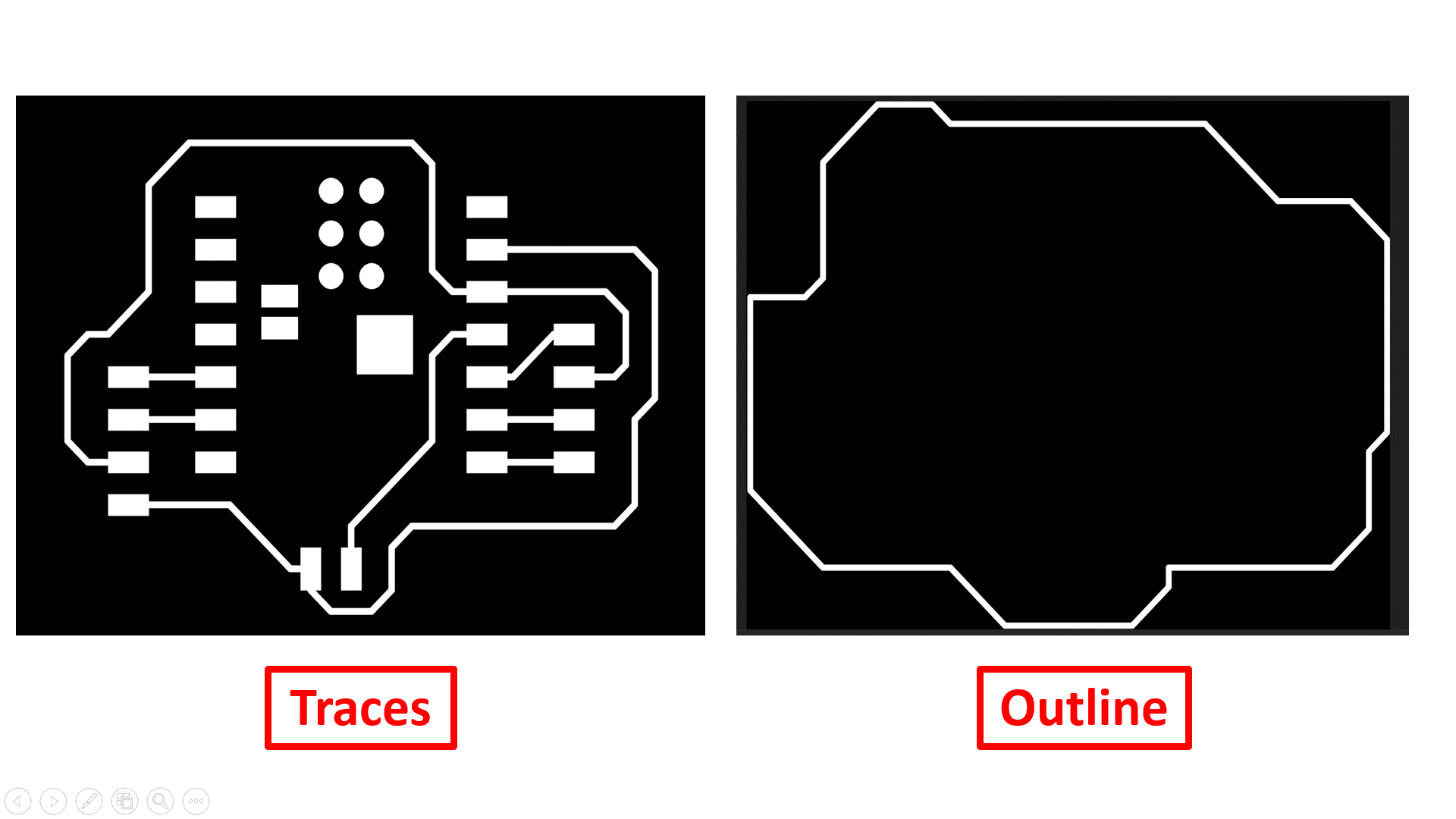
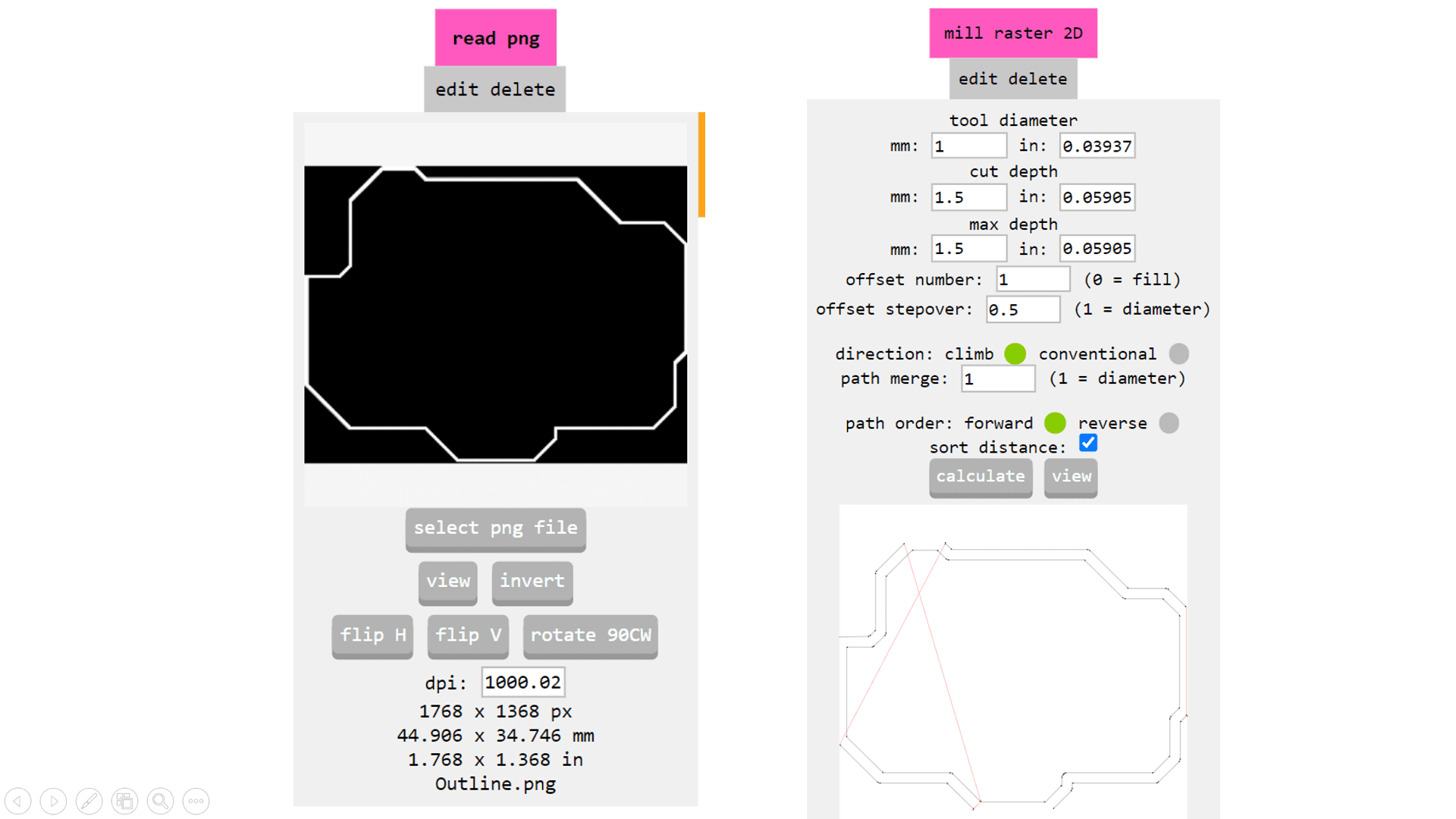
These are the PNG images of traces and outline exported for generating GCode for PCB Milling process.
Now, I used MIT Mods CE to generate GCode of image for PCB Milling process by inserting required parameters such as tool diameter, depth of cut and offset number.
Again, use same process to generate GCode of outline of PCB.
Here is the video of PCB Milling process of output devices PCB.
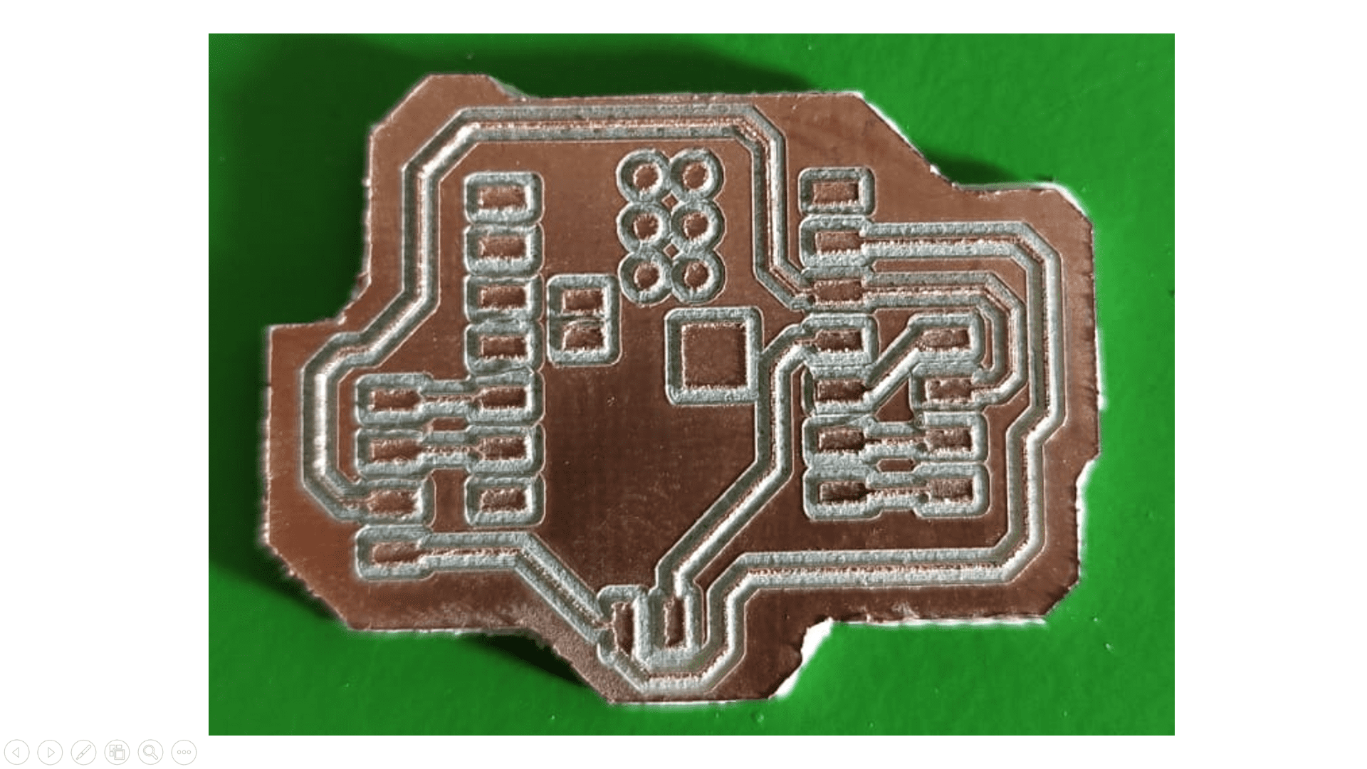
Here, I got the output.
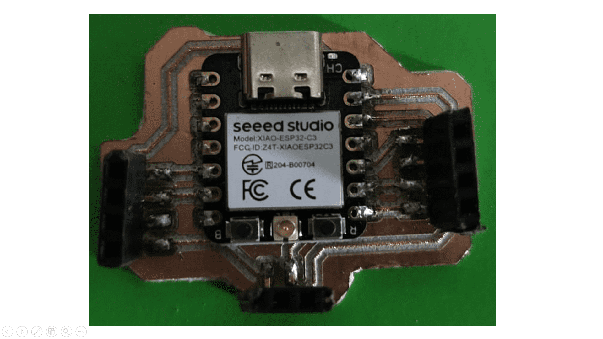
This is the glimpse after soldering the output deevice PCB. Finally, it is ready!
2) LCD


Now, its time for testing. Firstly, I tested all the devices separately with PCB board.
1) Buzzer
Code:-
    const int buzzerPin = 10; // D10 pin for buzzer


void setup() {

    pinMode(buzzerPin, OUTPUT); // Set buzzer pin as output

}


void loop() {

    // Turn buzzer on

    tone(buzzerPin, 1000); // Play a tone (optional, for audible indication)


    // Buzzer on time

    delay(1000); // Wait for 1 second (buzzer on)


    // Turn buzzer off

    noTone(buzzerPin);


    // Buzzer off time

    delay(2000); // Wait for 2 seconds (buzzer off)

}
Code Explaination:-
To connect the buzzer to the ESP32C3 microcontroller, I attached the positive terminal of the buzzer to pin D10 and the negative terminal to one of the ground (GND) pins on the microcontroller. In my code, I configured pin D10 as an output to control the buzzer. In the `setup` function, I initialized pin D10 as an output. In the `loop` function, I used the `tone` function to generate a 1000 Hz sound on the buzzer for 1 second, followed by a 2-second pause where the buzzer is turned off using the `noTone` function. This cycle repeats indefinitely, producing a sound for 1 second and remaining silent for 2 seconds.
Output:-
Code:-
#include < LiquidCrystal_I2C.h >
Code Explaination:-
#include < Wire.h >
// initialize the library by associating any needed LCD interface pin
// with the arduino pin number it is connected to
LiquidCrystal_I2C lcd(0x27, 16, 2);
void setup() {
// set up the LCD's number of columns and rows:
lcd.begin();
// Print a message to the LCD.
lcd.print("Siddhi :)");
}
void loop() {
// set the cursor to column 0, line 1
// (note: line 1 is the second row, since counting begins with 0):
lcd.setCursor(0, 1);
// print the number of seconds since reset:
lcd.print(millis() / 1000);
}
This code is designed to display a message and the elapsed time in seconds on a 16x2 LCD screen connected via I2C. The "LiquidCrystal_I2C" library is included to interface with the LCD. In the setup function, the LCD is initialized and the message "Siddhi :)" is printed on the first row. In the loop function, the cursor is set to the beginning of the second row, and the number of seconds since the microcontroller was reset is displayed, updating continuously. The LCD is connected to the I2C pins on the microcontroller, typically SDA and SCL.
Output:-