During Embedded Programming Week, we delved into various aspects crucial for understanding microcontrollers, analyzing their datasheets, and comparing performance and development workflows across different architectures. This documentation encapsulates our learnings from this intensive learning period.
- Understanding the data sheets of microcontrollers.
- Compare the performance and development workflows for other architectures.
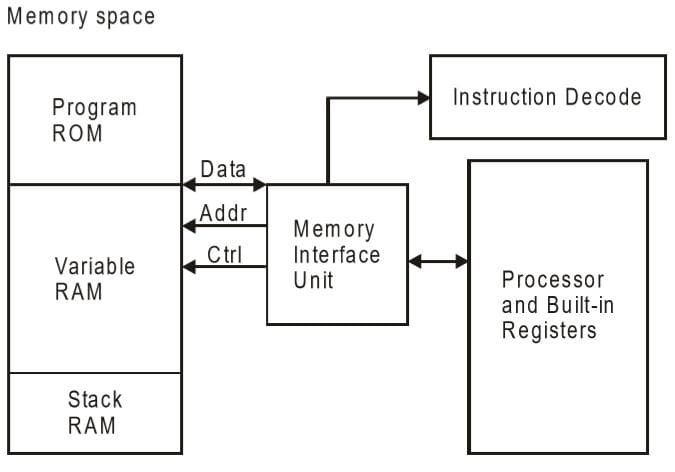
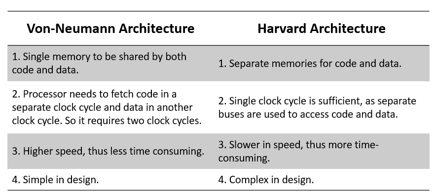
The Von Neumann architecture was first proposed by a computer scientist John von Neumann. In this architecture, one data path or bus exists for both instruction and data. As a result, the CPU does one operation at a time. It either fetches an instruction from memory, or performs read/write operation on data. So an instruction fetch and a data operation cannot occur simultaneously, sharing a common bus.
Von-Neumann architecture supports simple hardware. It allows the use of a single, sequential memory. Today's processing speeds vastly outpace memory access times, and we employ a very fast but small amount of memory (cache) local to the processor.
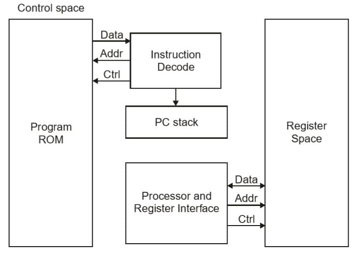
The Harvard architecture offers separate storage and signal buses for instructions and data. This architecture has data storage entirely contained within the CPU, and there is no access to the instruction storage as data. Computers have separate memory areas for program instructions and data using internal data buses, allowing simultaneous access to both instructions and data.
Programs needed to be loaded by an operator; the processor could not boot itself. In a Harvard architecture, there is no need to make the two memories share properties.
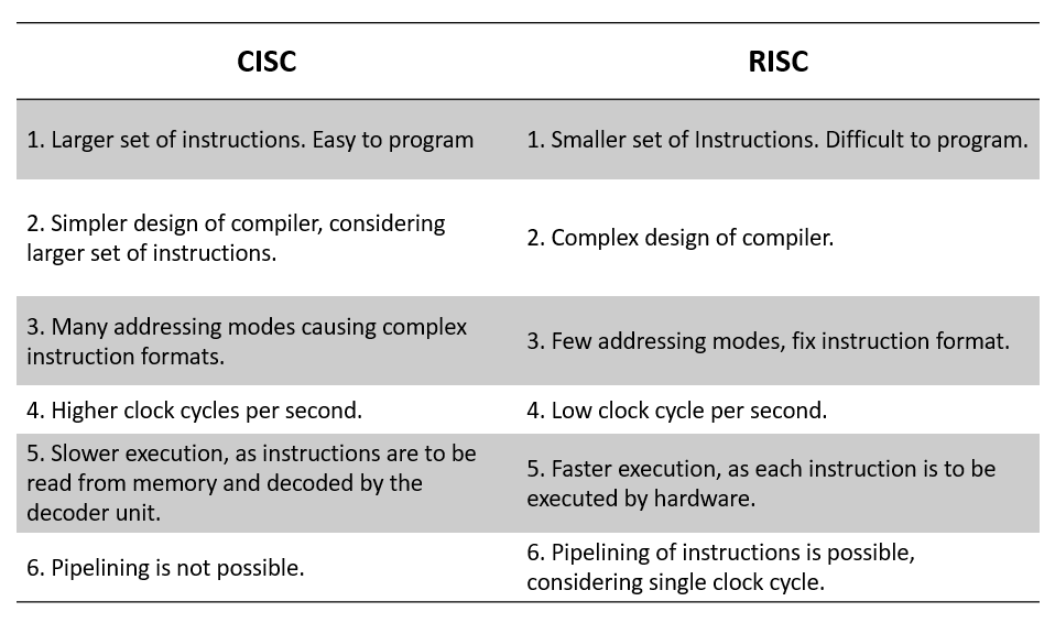
RISC and CISC are two different types of computer architectures that are used to design the microprocessors that are found in computers. The fundamental difference between RISC and CISC is that RISC (Reduced Instruction Set Computer) includes simple instructions and takes one cycle, while the CISC (Complex Instruction Set Computer) includes complex instructions and takes multiple cycles.
What is RISC?
In the RISC architecture, the instruction set of the computer system is simplified to reduce the execution time. RISC architecture has a small set of instructions that generally includes register-to-register operations.
The RISC architecture uses comparatively a simple instruction format that is easy to decode. The instruction length can be fixed and aligned to word boundaries. RISC processors can execute only one instruction per clock cycle.
What is CISC?
The CISC architecture comprises a complex instruction set. A CISC processor has a variable-length instruction format. In this processor architecture, the instructions that require register operands can take only two bytes.
In a CISC processor architecture, the instructions which require two memory addresses can take five bytes to comprise the complete instruction code. Therefore, in a CISC processor, the execution of instructions may take a varying number of clock cycles. The CISC processor also provides direct manipulation of operands that are stored in the memory.
The primary objective of the CISC processor architecture is to support a single machine instruction for each statement that is written in a high-level programming language.
CISC architectures have a large, complex instruction set and a less efficient execution pipeline. This allows CISC processors to perform a wider range of tasks, but they are not as fast as RISC processors when executing instructions.
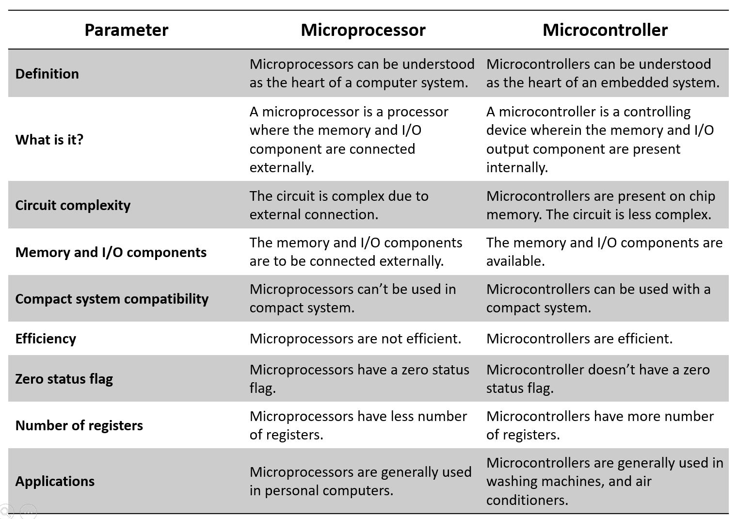
As its name implies, it is a processing device that converts data into information based on some sets of instructions. It is a very compact electronic chip due to which it is referred to as the microprocessor.
In other words, a processing device implemented on a single chip is called a microprocessor. A microprocessor is the most crucial component of a computer or any other computing device. Because, it is entirely responsible for processing data based on instructions to produce information.
In microcomputers, the microprocessor is used as the CPU (Central Processing Unit). A typical microprocessor consists of two major parts namely ALU (Arithmetic Logic Unit) and CU (Control Unit). Intel 8085 or 8086 processing chips are the examples of microprocessors.
Modern microprocessors consist of a small memory unit (cache memory) in addition to the ALU and CU. Now−a−days, microprocessors are being widely used in several applications such as desktop publishing, power plant control, multimeters, medical instruments, etc.
A microcontroller is an electronic system which consists of a processing element, a small memory (RAM, ROM, EPROM), I/O ports, etc. on a single chip. Therefore, a microcontroller is a tiny resemblance of a microcomputer. It is a quite small and low−cost electronic device which is used in several electronic appliances as the main functioning device.
In electronic systems such washing machines, air conditioners, refrigerators, etc., microcontrollers are used to automate the operation of the device based on user’s instructions. Hence, a microcontroller is the backbone of all embedded systems like microwave oven, washing machine, smart refrigerators, etc.
Microprocessors find their application in light sensing and controlling devices, temperature sensing and controlling devices, fire detection and other safety devices, smart measuring instruments, etc.
Arduino is a microcontroller-based platform that consists of open-source hardware, software, and programming tools. The concept of the Arduino ecosystem revolves around simplicity, making microcontrollers more accessible to the general public and great educational aids.
Arduino was created in 2003 by a group of academics at the Interaction Design Institute Ivrea in Italy. The platform was named after a bar in the same town where the academics met to discuss the project. One of the project's goals was to remove the barrier of entry for students who wanted to realize automation ideas but did not have enough resources to purchase expensive controllers or knowledge to build their printed circuit boards.
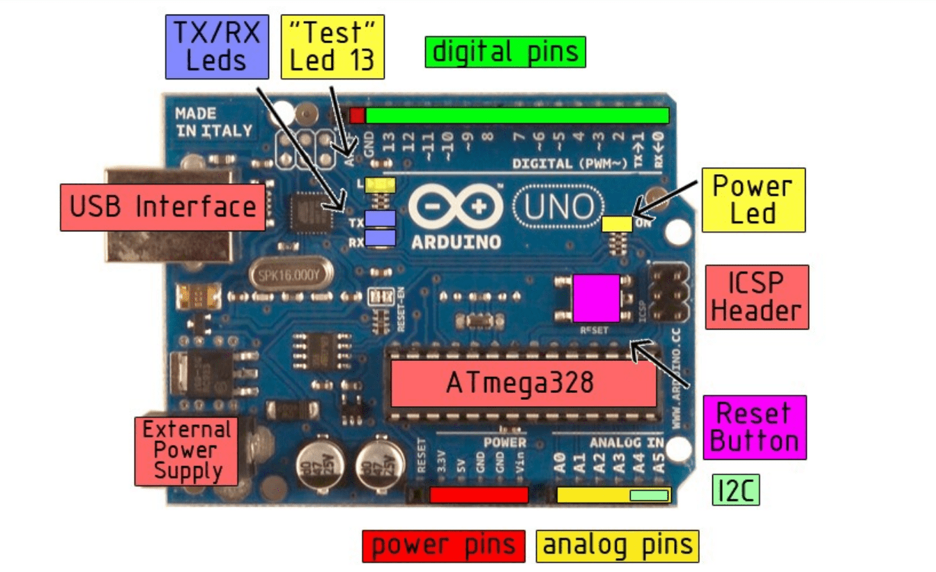
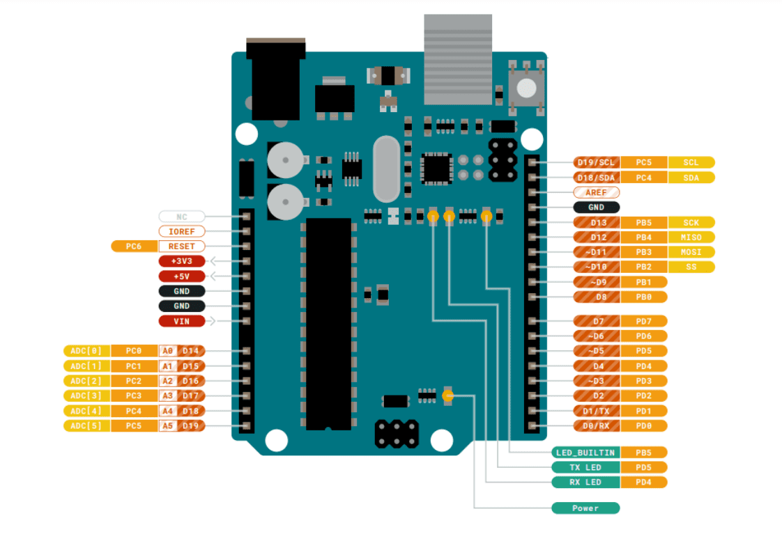
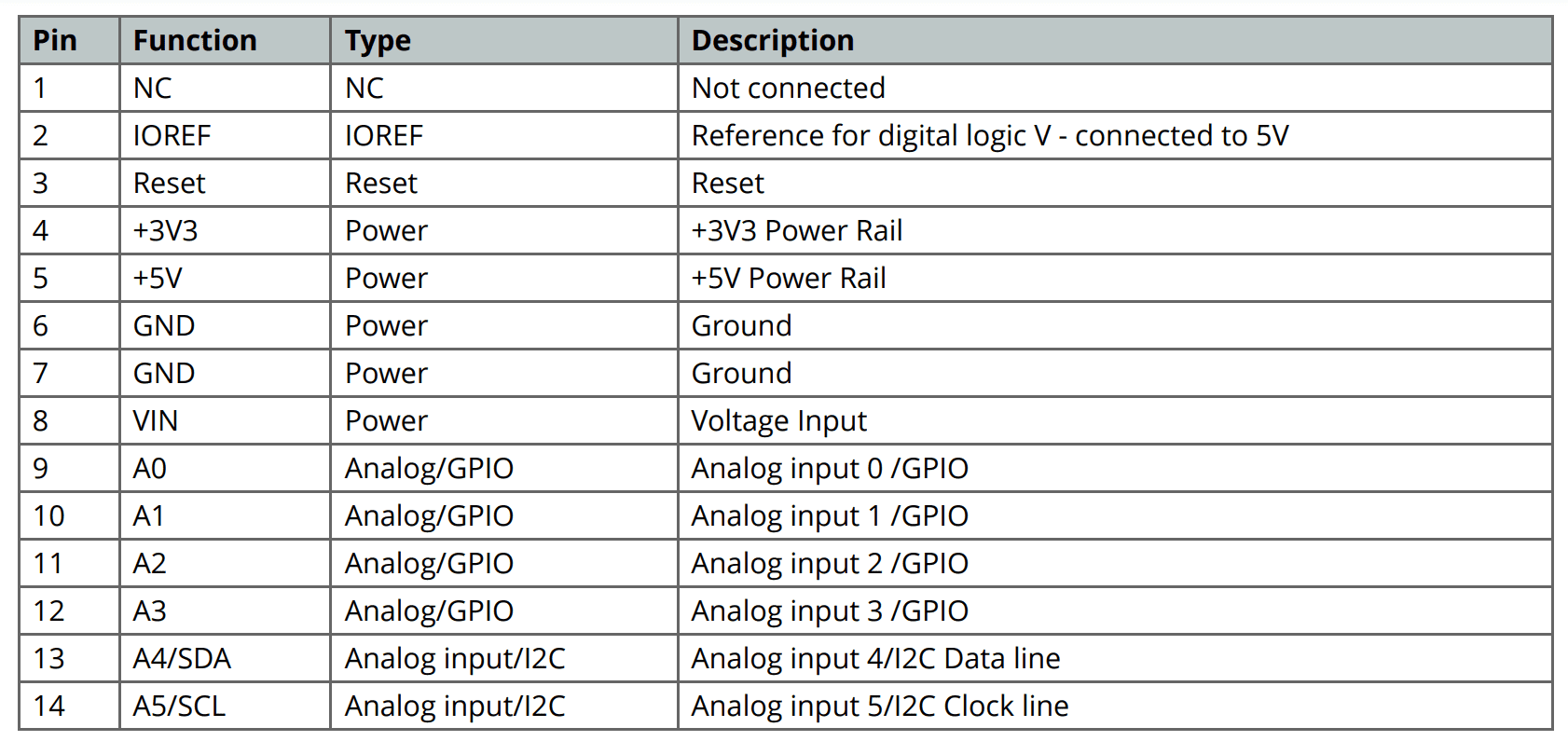
Microcontroller : ATmega328
Operating Voltage : 5V
Input Voltage (recommended) : 7-12V
Input Voltage (limits) : 6-20V
Digital I/O Pins : 14 (of which 6 provide PWM output)
Analog Input Pins : 6
DC Current per I/O Pin : 40 mA
DC Current for 3.3V Pin : 50 mA
Flash Memory : 32 KB of which 0.5 KB used by bootloader
SRAM : 2 KB
EEPROM : 1 KB
Clock Speed : 16 MHz
Length : 68.6 mm
Width : 53.4 mm
Weight : 25 g
Arduino Uno is open‐source hardware! You can build your own board using the
following files:
EAGLE FILES IN .ZIP
SCHEMATICS IN .PDF
BOARD SIZE IN .DXF
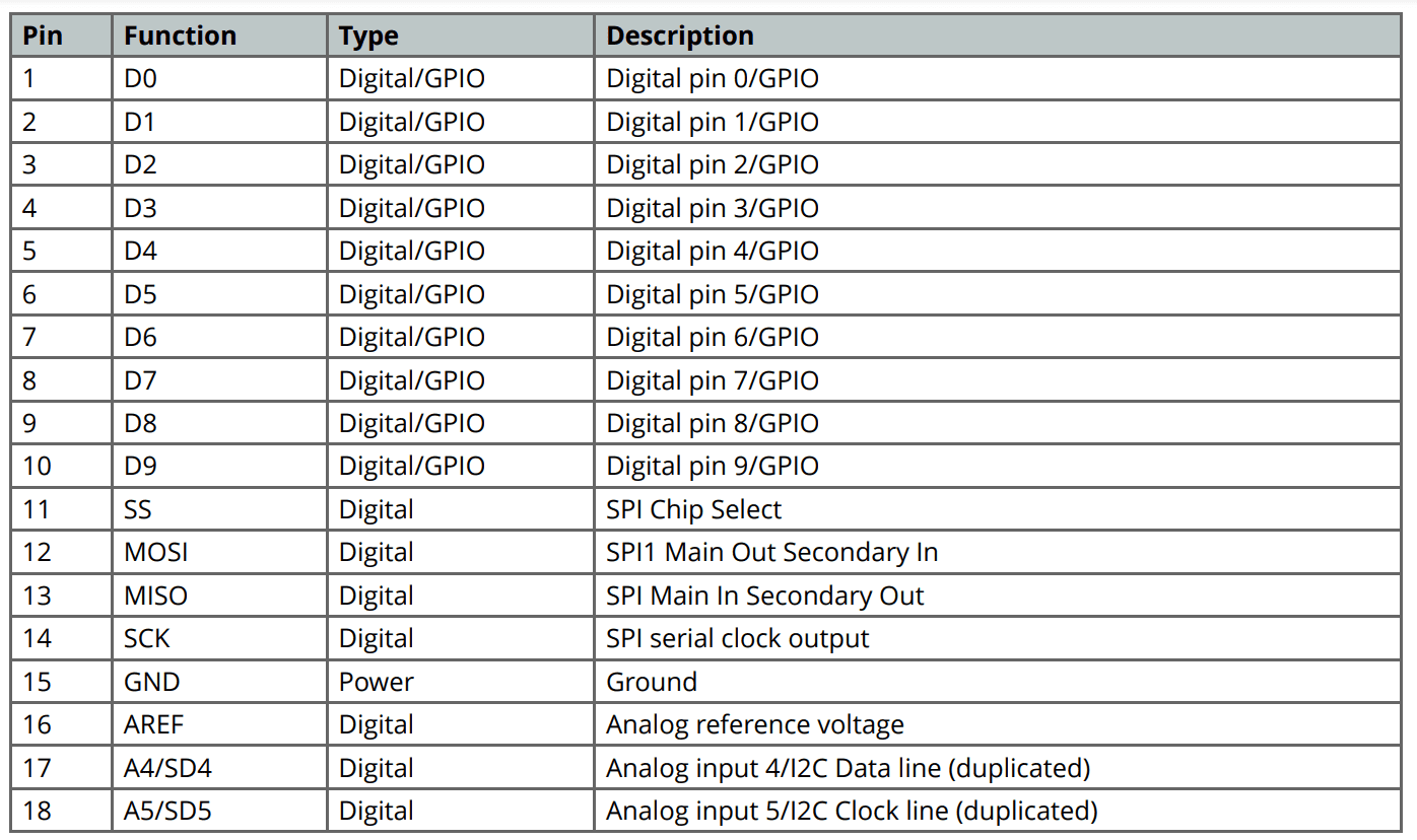
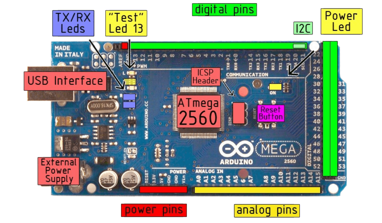
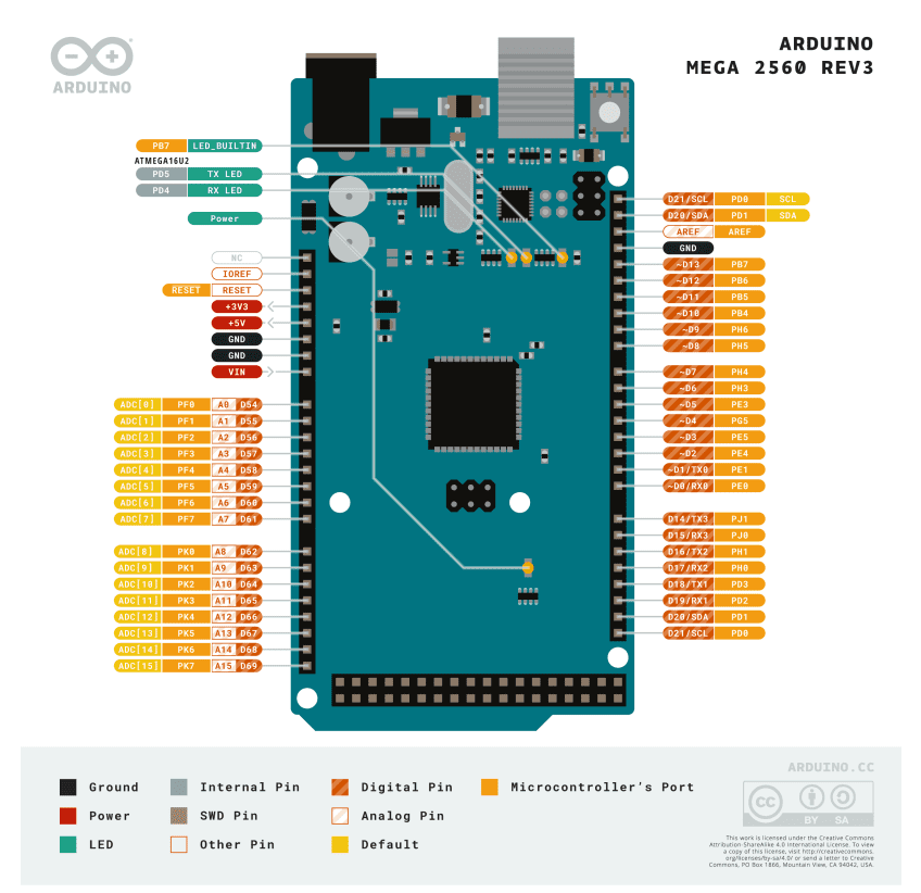
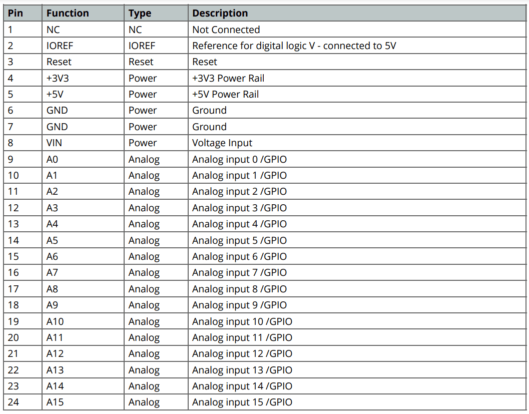
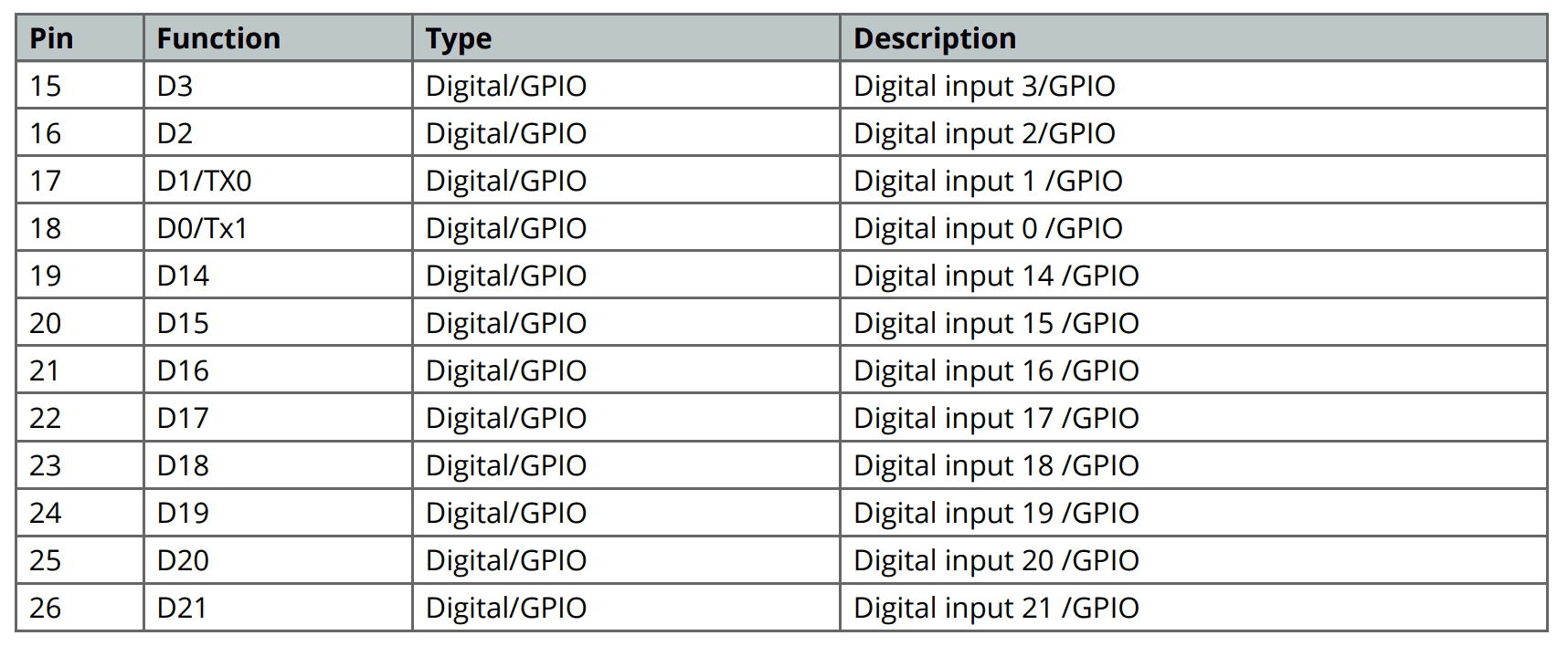
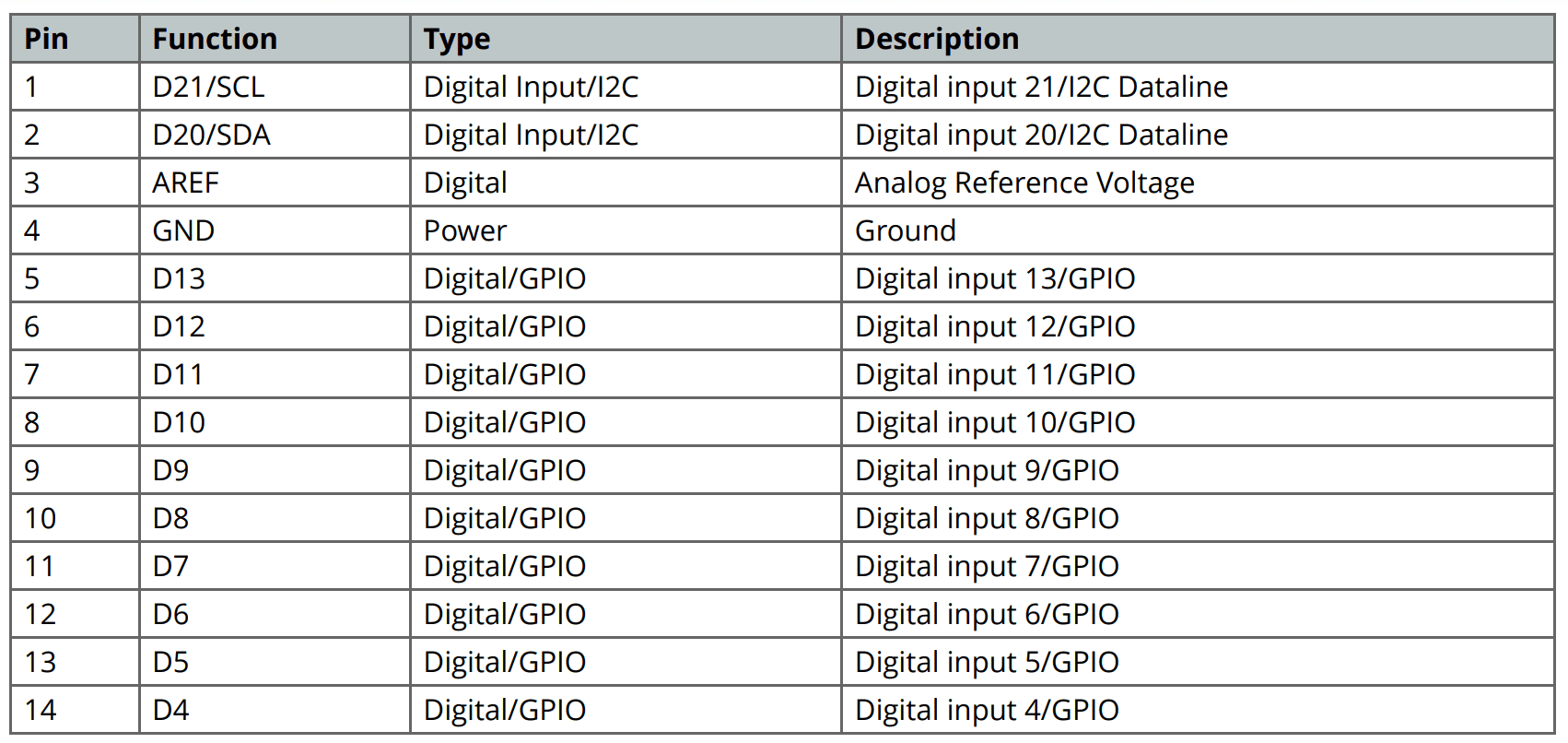
The Arduino Mega 2560 is a microcontroller board based on the ATmega2560 (datasheet). It has 54 digital input/output pins (of which 14 can be used as PWM outputs), 16 analog inputs, 4 UARTs (hardware serial ports), a 16 MHz crystal oscillator, a USB connection, a power jack, an ICSP header, and a reset button. It contains everything needed to support the microcontroller; simply connect it to a computer with a USB cable or power it with a AC-to-DC adapter or battery to get started. The Mega is compatible with most shields designed for the Arduino Duemilanove or Diecimila. The Mega 2560 is an update to the Arduino Mega, which it replaces.
Microcontroller : ATmega2560
Operating Voltage : 5V
Input Voltage (recommended) : 7-12V
Input Voltage (limits) : 6-20V
Digital I/O Pins : 54 (of which 14 provide PWM output)
Analog Input Pins : 16
DC Current per I/O Pin : 40 mA
DC Current for 3.3V Pin : 50 mA
Flash Memory : 256 KB of which 8 KB used by bootloader
SRAM : 8 KB
EEPROM : 4 KB
Clock Speed : 16 MHz
EAGLE FILES IN .ZIP
SCHEMATICS IN .PDF
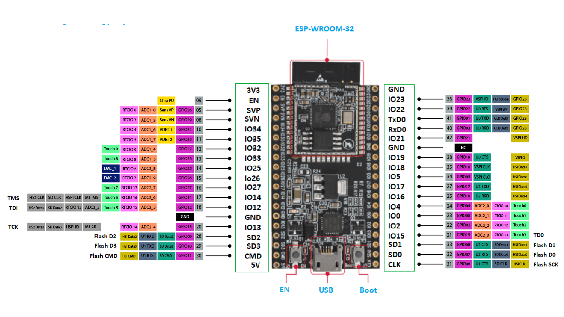
ESP32 is a series of low-cost, low-power system on a chip microcontrollers with integrated Wi-Fi and dual-mode Bluetooth. The ESP32 series employs either a Tensilica Xtensa LX6 microprocessor in both dual-core and single-core variations, Xtensa LX7 dual-core microprocessor or a single-core RISC-V microprocessor and includes built-in antenna switches, RF balun, power amplifier, low-noise receive amplifier, filters, and power-management modules. ESP32 is created and developed by Espressif Systems, a Chinese company based in Shanghai, and is manufactured by TSMC using their 40 nm process. It is a successor to the ESP8266 microcontroller.
Microcontroller : ESP32-WROOM-32
Clock Speed (MHz) : Up to 240
Operating Voltage (V) : 3.3 (2.2-3.6)
Analog Input Pins : 12
Digital I/O Pins : 32
DC Current per Pin (mA) : Varies (up to 6)
Flash Memory (KB) : 4096
SRAM Memory (KB) : 320
Wireless Connectivity : Wi-Fi & Bluetooth
USB Interface : Yes
Development Environment : Arduino IDE/ESP-IDF
Community Support : Moderate
Price (USD) : 10-15
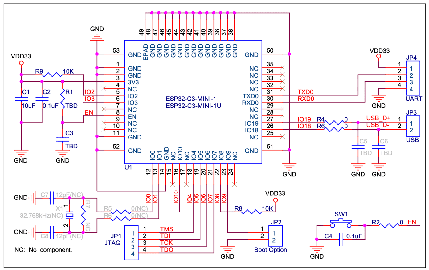
The ESP32-C3 is a relatively new addition to the Espressif Systems product line, with its development and initial launch happening in 2022. It's still evolving with new variants, suggesting continued efforts to establish its position in the microcontroller market.
Wi-Fi
• IEEE 802.11b/g/n-compliant
• Supports 20 MHz, 40 MHz bandwidth in 2.4 GHz band
• 1T1R mode with data rate up to 150 Mbps
• Wi-Fi Multimedia (WMM)
• TX/RX A-MPDU, TX/RX A-MSDU
• Immediate Block ACK
• Fragmentation and defragmentation
• Transmit opportunity (TXOP)
• Automatic Beacon monitoring (hardware TSF)
• 4 × virtual Wi-Fi interfaces
• Simultaneous support for Infrastructure BSS in Station mode, SoftAP mode, Station + SoftAP mode, and
promiscuous mode
Note that when ESP32-C3 scans in Station mode, the SoftAP channel will change along with the Station
channel
• Antenna diversity
• 802.11mc FTM
Bluetooth®
• Bluetooth LE: Bluetooth 5, Bluetooth mesh
• High power mode (20 dBm)
• Speed: 125 Kbps, 500 Kbps, 1 Mbps, 2 Mbps
• Advertising extensions
• Multiple advertisement sets
• Channel selection algorithm #2
• Internal co-existence mechanism between Wi-Fi and Bluetooth to share the same antenna
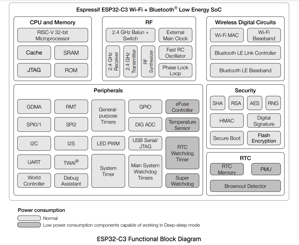
CPU and Memory
• 32-bit RISC-V single-core processor, up to 160 MHz
• CoreMark® score:
– 1 core at 160 MHz: 407.22 CoreMark; 2.55 CoreMark/MHz
• 384 KB ROM
• 400 KB SRAM (16 KB for cache)
• 8 KB SRAM in RTC
• In-package flash
• SPI, Dual SPI, Quad SPI, and QPI interfaces that allow connection to multiple off-package flash
• Access to flash accelerated by cache
• Supports flash in-Circuit Programming (ICP)
Advanced Peripheral Interfaces
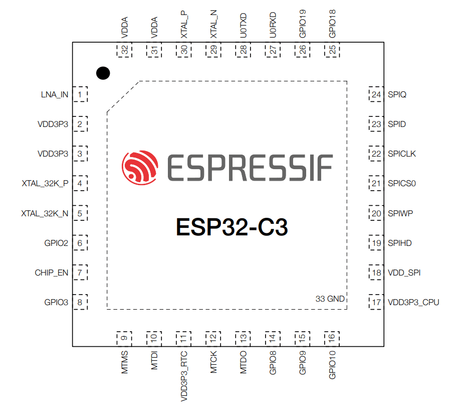
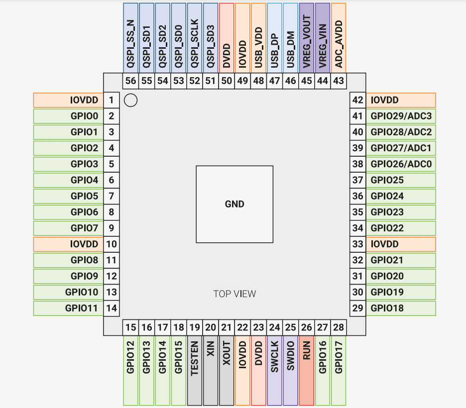
• 22 or 16 programmable GPIOs
• Digital interfaces:
– 3 × SPI
– 2 × UART
– 1 × I2C
– 1 × I2S
– Remote control peripheral, with 2 transmit channels and 2 receive channels
– LED PWM controller, with up to 6 channels
– Full-speed USB Serial/JTAG controller
– General DMA controller (GDMA), with 3 transmit channels and 3 receive channels
– 1 × TWAI® controller compatible with ISO 11898-1 (CAN Specification 2.0)
• Analog interfaces:
– 2 × 12-bit SAR ADCs, up to 6 channels
– 1 × temperature sensor
• Timers:
– 2 × 54-bit general-purpose timers
– 3 × digital watchdog timers
– 1 × analog watchdog timer
– 1 × 52-bit system timer
Power Management
• Fine-resolution power control through a selection of clock frequency, duty cycle, Wi-Fi operating modes,
and individual power control of internal components
• Four power modes designed for typical scenarios: Active, Modem-sleep, Light-sleep, Deep-sleep
• Power consumption in Deep-sleep mode is 5 µA
• RTC memory remains powered on in Deep-sleep mode
Security
• Secure boot - permission control on accessing internal and external memory
• Flash encryption - memory encryption and decryption
• 4096-bit OTP, up to 1792 bits for users
• Cryptographic hardware acceleration:
– AES-128/256 (FIPS PUB 197)
– SHA Accelerator (FIPS PUB 180-4)
– RSA Accelerator
– Random Number Generator (RNG)
– HMAC
– Digital signature
RF Module
• Antenna switches, RF balun, power amplifier, low-noise receive amplifier
• Up to +21 dBm of power for an 802.11b transmission
• Up to +20 dBm of power for an 802.11n transmission
• Up to -105 dBm of sensitivity for Bluetooth LE receiver (125 Kbps)
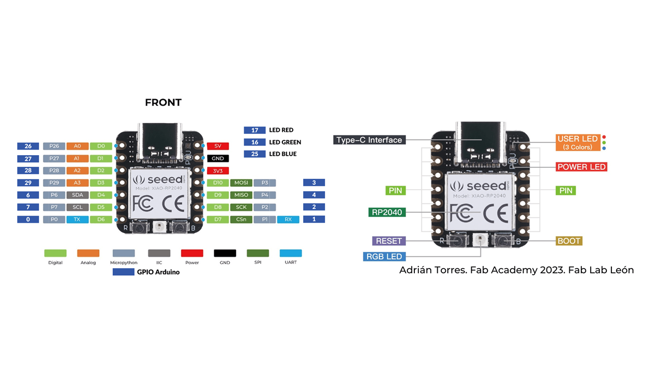
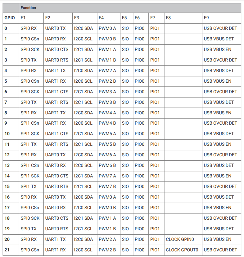
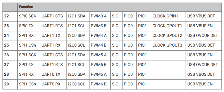
The Xiao RP2040 is a small and versatile microcontroller board that is well-suited for a variety of projects, from simple experiments to more complex applications.
Processor: Dual-core ARM Cortex M0+ processor, running up to 133 MHz
Memory: 264KB of SRAM, 2MB of flash memory
I/O:
- 11 digital pins (with 11 PWM pins)
- 4 analog pins
- 1 I2C interface
- 1 UART interface
- 1 SPI interface
Other features:
- USB Type-C for power and programming
- User-programmable RGB LED
- Onboard LEDs for power and status
- Breadboard-friendly design
- Supports Arduino, MicroPython, and CircuitPython

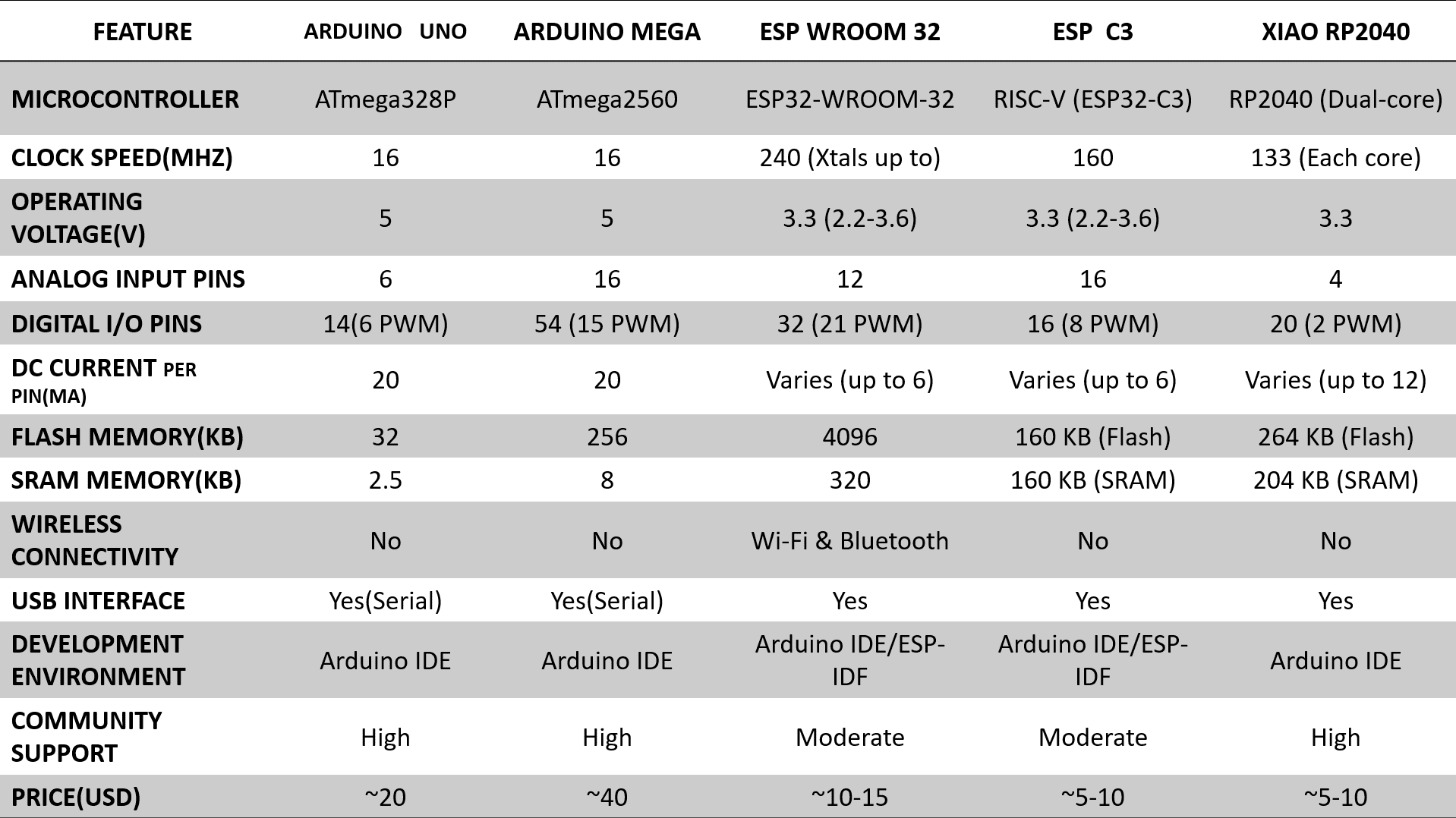
1. Arduino Uno and Mega are classic boards known for their ease of use and large user base.
2. ESP Wroom 32 offers built-in Wi-Fi and Bluetooth connectivity, making it ideal for IoT projects.
3. ESP C3 is a newer, low-power option from Espressif Systems with lower cost.
4. Xiao RP2040 is a compact and affordable board based on the powerful RP2040 dual-core microcontroller.
5. The choice between these boards depends on your specific project requirements, such as processing power, connectivity needs, budget, and familiarity with the development environment.
for more information about group assignment you can click here.
In the individual assignment, I will be programming the ESP Wroom 32, ESP C3, and Xiao RP 2040 using embedded programming on Arduino IDE and MicroPython on Thonny.
-write a program for a microcontroller development board that you made,
-interact (with local input &/or output devices) and communicate (with remote wired or wireless devices)
The Seeed Studio XIAO RP2040 is as small as the Seeed Studio XIAO SAMD21 but it's more powerful. On one hand, it carries the powerful Dual-core RP2040 processor that can flexible clock running up to 133 MHz which is a low-power microcontrollers. On the Seeed Studio XIAO RP2040 there is also 264KB of SRAM, and 2MB of on-board Flash memory which can provide more program to save and run. On the other hand, this little board has good performance in processing but needs less power.
All in all, it is designed in a tiny size as small as a thumb(20x17.5mm) and can be used for wearable devices and small projects.
There are 14 GPIO PINs on Seeed Studio XIAO RP2040, on which there are 11 digital pins, 4 analog pins, 11 PWM Pins,1 I2C interface, 1 UART interface, 1 SPI interface, 1 SWD Bonding pad interface.
1. Seeed Studio XIAO RP2040 x1
2. Type-C cable x1
3. PC or Laptop or Raspberry Pi 4 x1
1. Arduino IDE. (For C++)
2. Thonny editor. (For MicroPython)
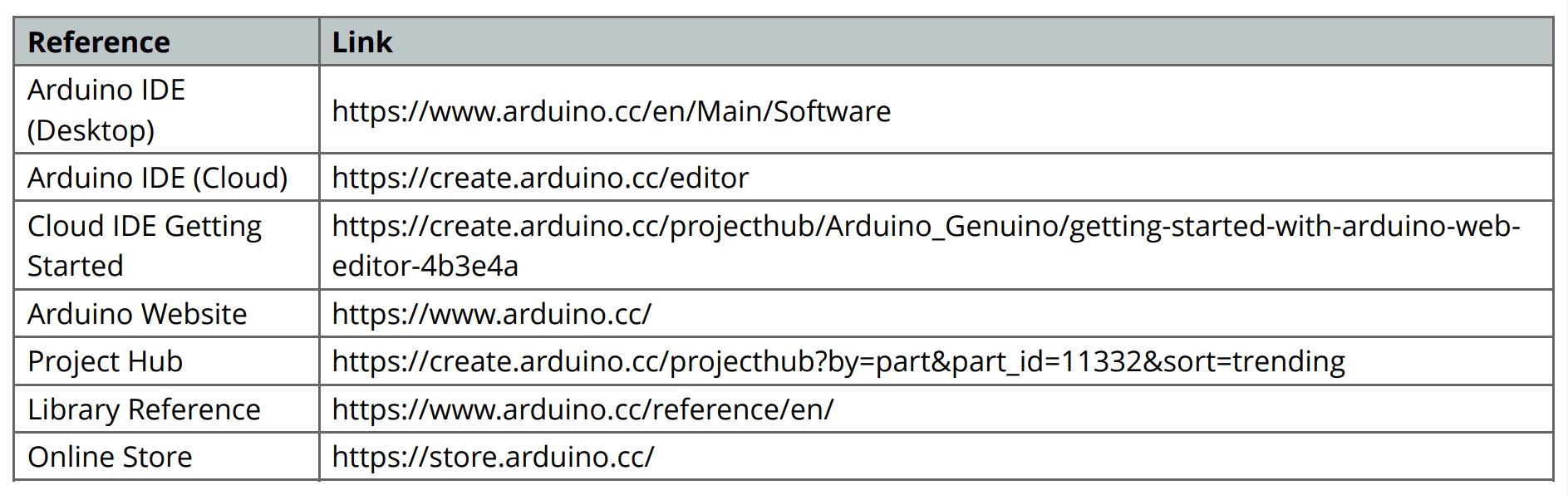
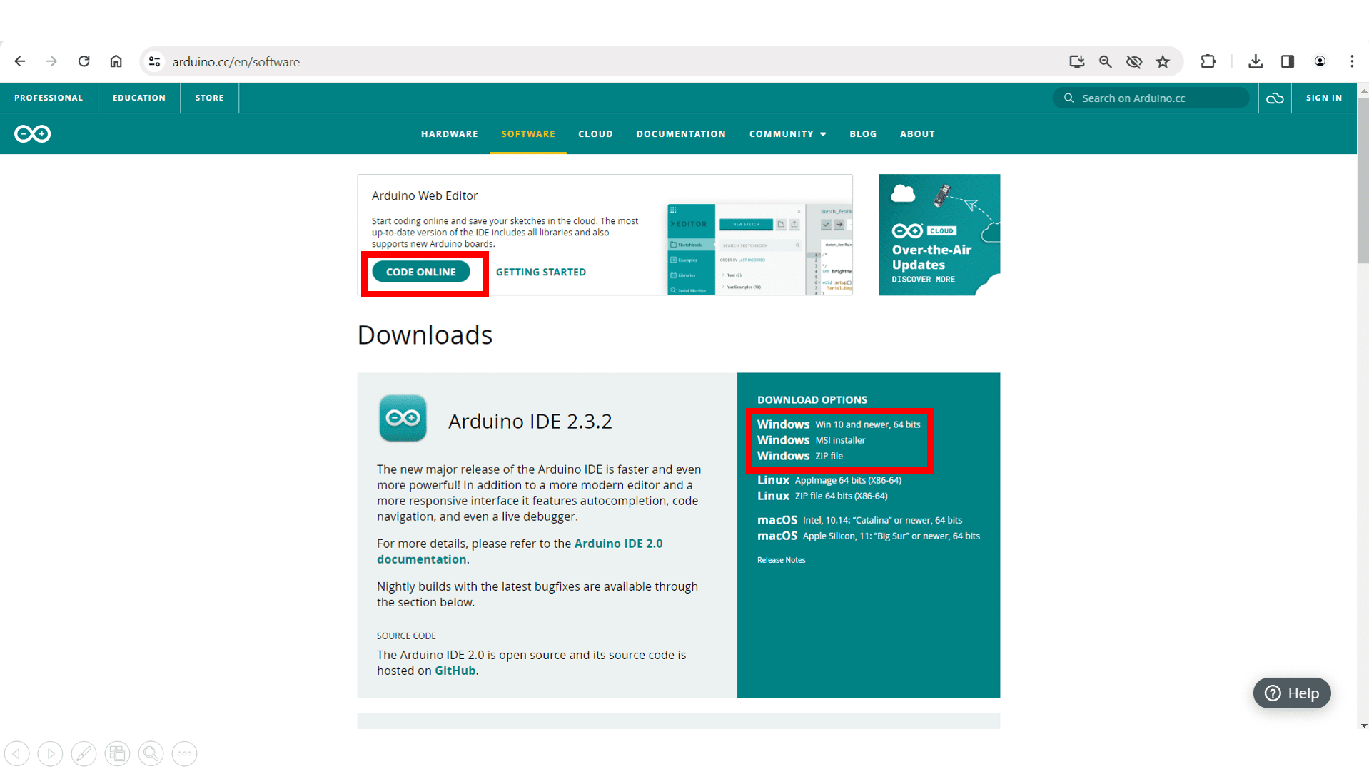
Download and Install the latest version of Arduino IDE according to your operating system or you can code online.
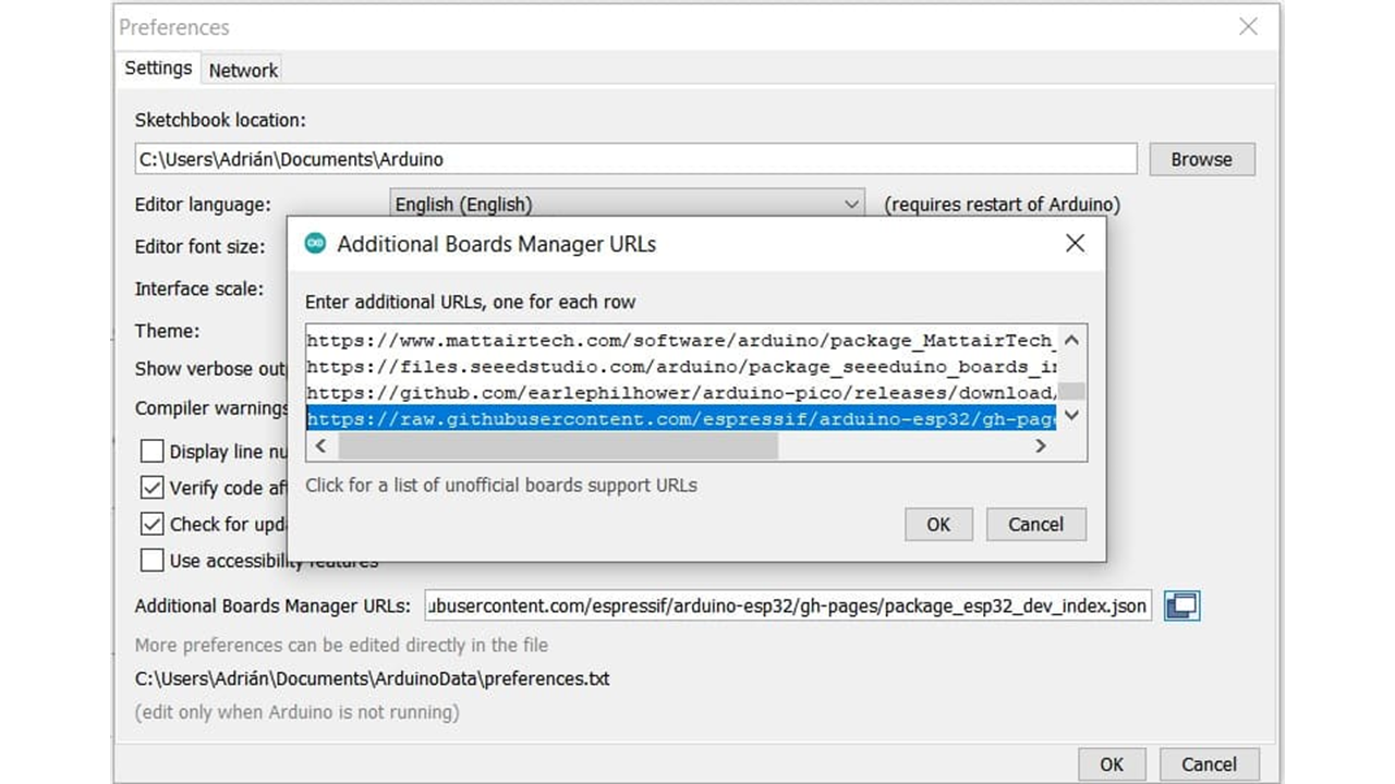
In File->Preferences, we will add the URL of the additional boards that you can find here. We need the Arduino-Pico by Earlephilhower.
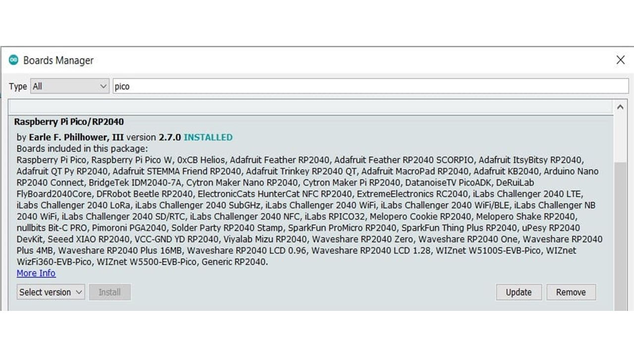
The next step is to download Pico in the boards manager. Tools->Board->Board manager
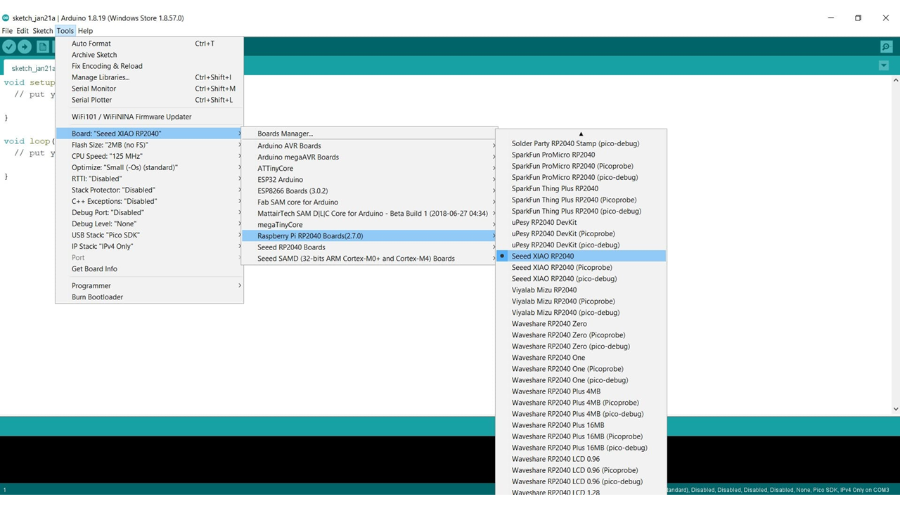
We configure the Arduino IDE for the Seeed Studio XIAO RP2040. The Seeed Studio XIAO RP2040 will appear in the COM port, in my case in COM 3.
I programmed the board to blink all the LEDs, and I also utilized the push button to toggle the LEDs on or off.
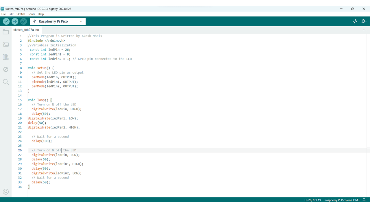
These are some programs that i have used on my board
//This Program is Written by Akash Mhais

        #include

        //Variables Initialization

         const int ledPin = 26;

         const int ledPin1 = 0;

         const int ledPin2 = 1; // GPIO pin connected to the LED


        void setup() {

          // Set the LED pin as output

          pinMode(ledPin, OUTPUT);

          pinMode(ledPin1, OUTPUT);

          pinMode(ledPin2, OUTPUT);

        }


        void loop() {

          // Turn on & off the LED

          digitalWrite(ledPin, HIGH);

          delay(50);

        digitalWrite(ledPin1, LOW);

        delay(50);

        digitalWrite(ledPin2, HIGH);


          // Wait for a second

          delay(100);


          // Turn on & off the LED

          digitalWrite(ledPin, LOW);

          delay(50);

          digitalWrite(ledPin1, HIGH);

          delay(50);

          digitalWrite(ledPin2, LOW);

          // Wait for a second

          delay(50);

        }
            //This Program is Written by Akash Mhais

            #include


            const int ledPin = 26;

            const int ledPin1 = 0;

            const int ledPin2 = 1; // GPIO pin connected to the LED


           void setup() {

             // Set the LED pin as output

             pinMode(ledPin, OUTPUT);

             pinMode(ledPin1, OUTPUT);

             pinMode(ledPin2, OUTPUT);

           }


           void loop() {

             // Turn on the LED

             digitalWrite(ledPin, HIGH);

           digitalWrite(ledPin1, HIGH);

           digitalWrite(ledPin2, HIGH);


             // Wait for a second

             delay(1000);


             // Turn off the LED

             digitalWrite(ledPin, LOW);

             digitalWrite(ledPin1, LOW);

             digitalWrite(ledPin2, LOW);

             // Wait for a second

             delay(1000);

           }
                //This Program is Written by Akash Mhais

                #include


                    const int redLedPin = 0;

                    const int greenLedPin = 1;

                    const int blueLedPin = 26;

                    const int buttonPin = 27; // Replace with the actual button pin if different


                    int buttonState = LOW; // Initial button state

                    bool ledOn = false;   // Flag to track LED state


                    void setup() {

                      // Set LED pins as outputs

                      pinMode(redLedPin, OUTPUT);

                      pinMode(greenLedPin, OUTPUT);

                      pinMode(blueLedPin, OUTPUT);


                      // Set button pin as input with internal pull-up resistor

                      pinMode(buttonPin, INPUT_PULLUP);


                      // Initially turn off LEDs

                      digitalWrite(redLedPin, LOW);

                      digitalWrite(greenLedPin, LOW);

                      digitalWrite(blueLedPin, LOW);

                    }


                    void loop() {

                      // Read the button state

                      buttonState = digitalRead(buttonPin);


                      // Toggle LED state on button press (rising edge)

                      if (buttonState == LOW && !ledOn) {

                        ledOn = true;

                        digitalWrite(redLedPin, HIGH);

                        digitalWrite(greenLedPin, HIGH);

                        digitalWrite(blueLedPin, HIGH);

                      } else if (buttonState == HIGH && ledOn) {

                        ledOn = false;

                        digitalWrite(redLedPin, LOW);

                        digitalWrite(greenLedPin, LOW);

                        digitalWrite(blueLedPin, LOW);

                      }

                    }
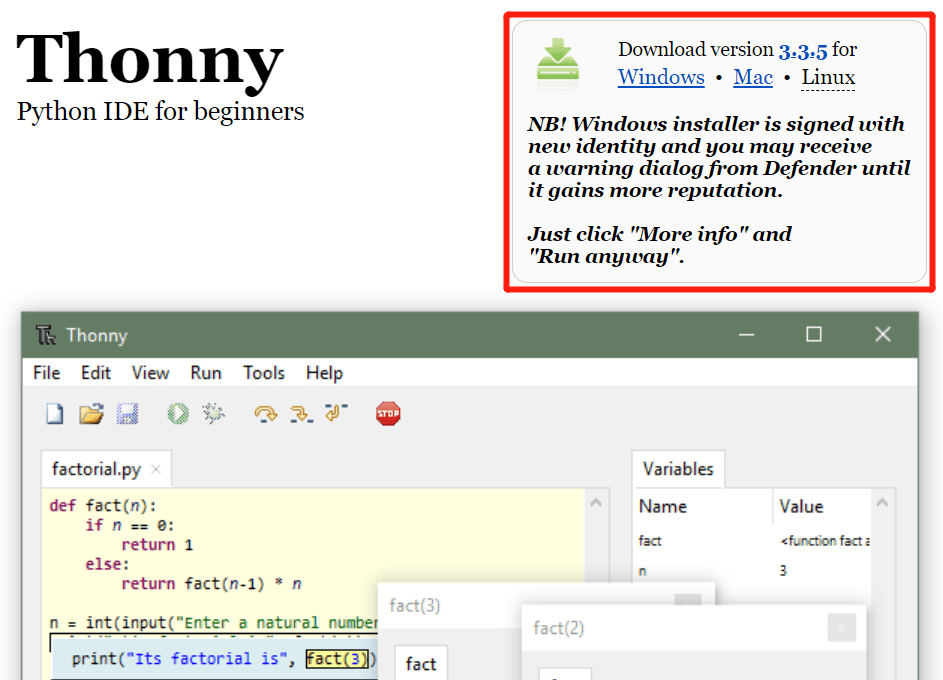
Step 1: Download and Install the latest version of Thonny editor according to your operating system.
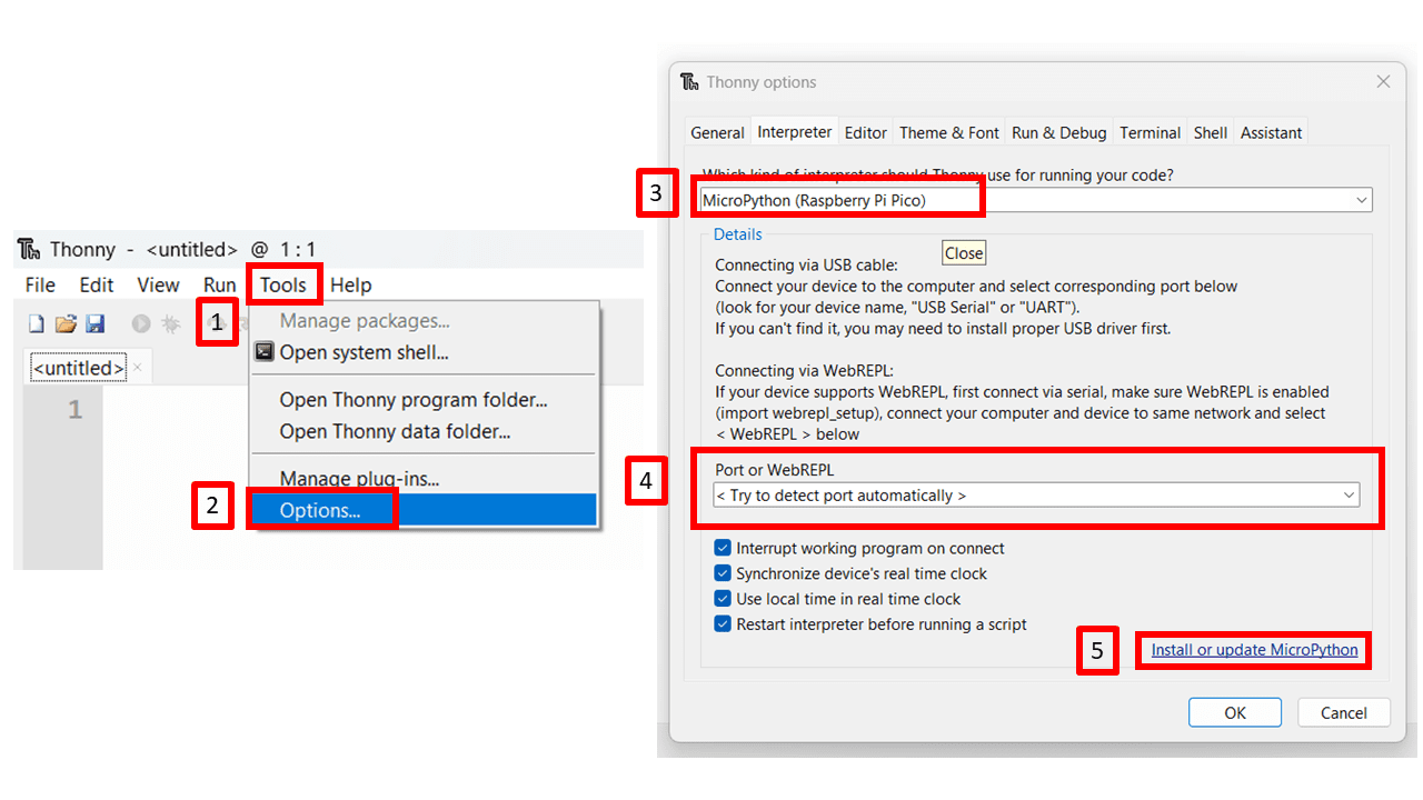
Step 2: Launch the Thonny. Step 3: Click "Tools-->Options" to open the settings. Step 4: Chose the "Interpreter" interface and select the device as "MicroPython(Raspberry Pi Pico)" and the port as "Try to detect prot automatically"
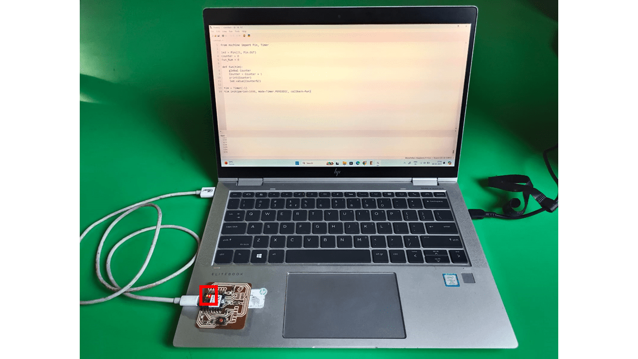
Connect Seeed Studio XIAO RP2040 to the PC and Light it up
Step 1. Press and hold the "BOOT" button and then connect the Seeed Studio XIAO RP2040 to the PC through the Type-C cable. If it works well, there is an "RPI-RP2" desk shown on the PC.
Step 2. Click Install or update MicroPython.
It will then automatically search for the device and display it on the Target Volume. In the version selection in Micropython below, we just leave the default.
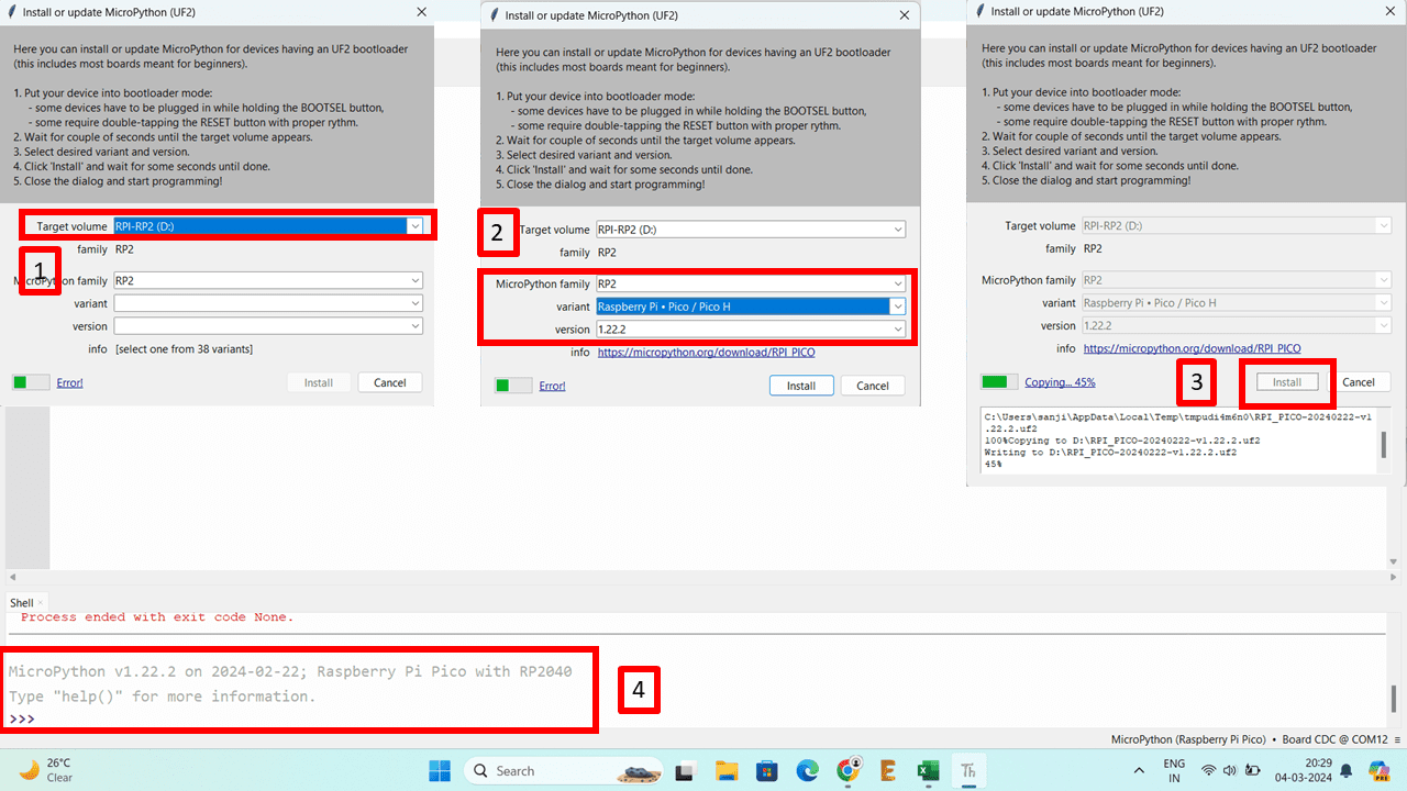
Click on the Install button and close this page when the installation status says Done. The following information will be shown on the interface once the firmware is complete.
Step 3. Copy the following codes to Thonny.
from machine import Pin, Timer


    led = Pin(25, Pin.OUT)

    Counter = 0

    Fun_Num = 0


    def fun(tim):

        global Counter

        Counter = Counter + 1

        print(Counter)

        led.value(Counter%2)


    tim = Timer(-1)

    tim.init(period=1000, mode=Timer.PERIODIC, callback=fun)
Step 4. Upload the codes by clicking the "Run current script" button. For the first time, Thonny will ask where you want to save your codes file. Both This Computer and Raspberry Pi Pico are fine.
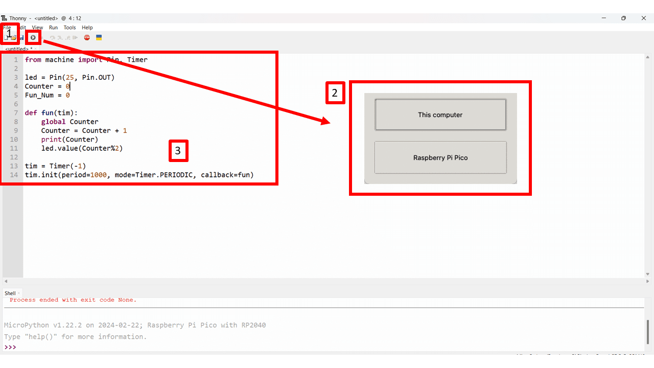
If it works well, you will see the LED light turn on and off once a second. And the output of the increasing number will as well be displayed in the Shell.
Light up RGB LED on the Seeed Studio XIAO RP2040
There is an RGB LED equipped in the Seeed Studio XIAO RP2040 and we are going to light it up by MicroPython. It is required a third-party library so we need to add an additional library first.
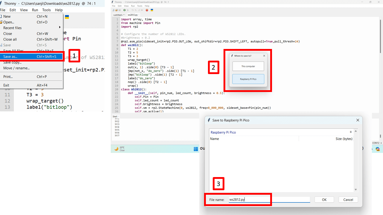
Step 1. Download the ws2812.py library and open it with Thonny.
Step 2. Click "File-->Save as" and save the library.
Chose the "Raspberry Pi Pico" as the location we save.
Make sure the saved file name is "ws2812.py", otherwise it will not work.
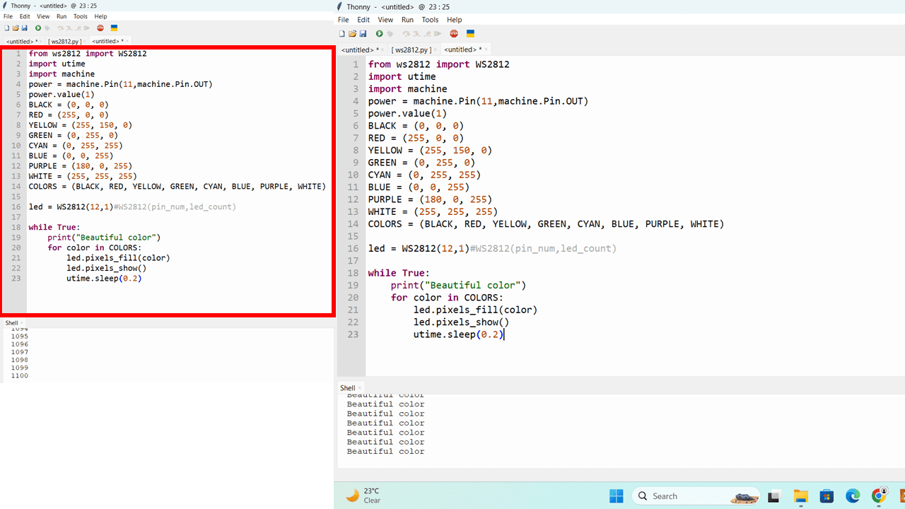
Step 3. Copy the following codes to Thonny.
from ws2812 import WS2812

    import utime

    import machine

    power = machine.Pin(11,machine.Pin.OUT)

    power.value(1)

    BLACK = (0, 0, 0)

    RED = (255, 0, 0)

    YELLOW = (255, 150, 0)

    GREEN = (0, 255, 0)

    CYAN = (0, 255, 255)

    BLUE = (0, 0, 255)

    PURPLE = (180, 0, 255)

    WHITE = (255, 255, 255)

    COLORS = (BLACK, RED, YELLOW, GREEN, CYAN, BLUE, PURPLE, WHITE)


    led = WS2812(12,1)#WS2812(pin_num,led_count)


    while True:

        print("Beautiful color")

        for color in COLORS:

            led.pixels_fill(color)

            led.pixels_show()

            utime.sleep(0.2)
Step 4. Upload the codes by clicking the "Run current script" button. For the first time, Thonny will ask where you want to save your codes file. Both This Computer and Raspberry Pi Pico are fine.
If it works well, you will see the RGB LED light convert and flash the lights. And the output of the text "Beautiful Color" will as well be displayed in the Shell.
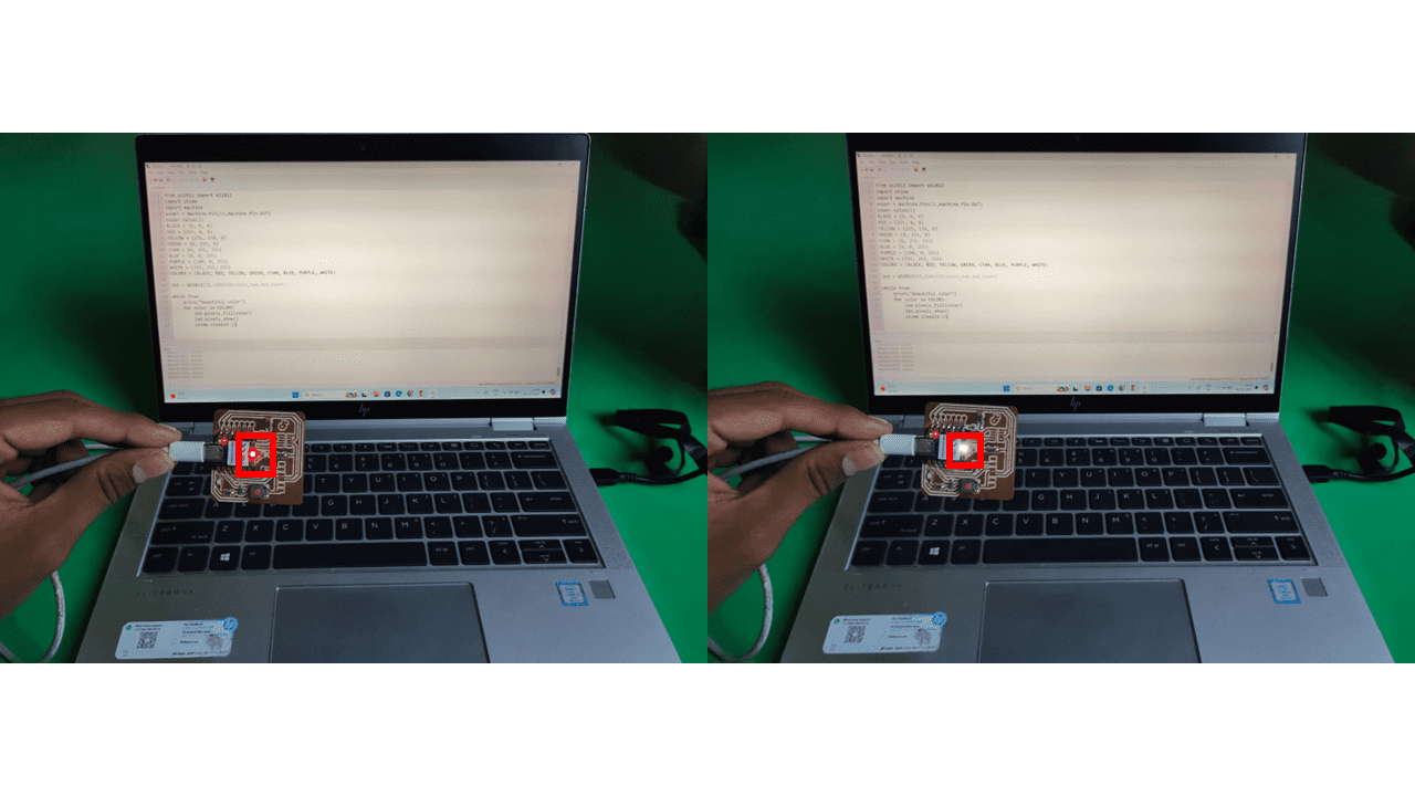
Similarly I programmed for the 3 LEDs Which I have soldered on the board and going to use micropython on thonny.
The steps are similar to the above one
1. Firstly, connect the RP2040 board to the laptop.
2. Open the Thonny Editor.
3. Go to Tools and select Options.
4. Switch to the Interpreter tab and select the device as "MicroPython (Raspberry Pi Pico)" and the port as "Try to detect port automatically."
5. Press and hold the "BOOT" button, then connect the Seeed Studio XIAO RP2040 to the PC. If it works correctly, an "RPI-RP2" desk will be shown on the PC.
6. Click Install or update MicroPython.
7. Copy the code below and click on "Run current script" or press F5.
        from machine import Pin


# LED pin definitions

led_pin = 26

led_pin1 = 0

led_pin2 = 1


# Initialize LED pins as outputs

led = Pin(led_pin, Pin.OUT)

led1 = Pin(led_pin1, Pin.OUT)

led2 = Pin(led_pin2, Pin.OUT)


# Function simulating delay behavior

def delay_ms(milliseconds):

    import time

    time.sleep_ms(milliseconds)


def main():

    while True:

        # Turn on LED, toggle others

        led.value(1)  # Equivalent to HIGH in MicroPython

        led1.value(0)  # Equivalent to LOW in MicroPython

        led2.value(1)

        delay_ms(50)


        # Turn off LED, toggle others

        led.value(0)

        led1.value(1)

        led2.value(0)

        delay_ms(50)


if _name_ == "_main_":

    main()  # Call the main function to start the program
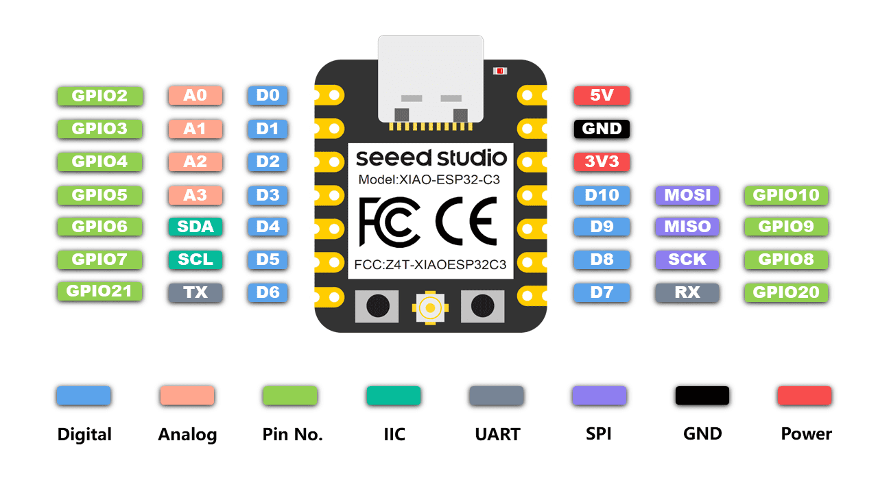
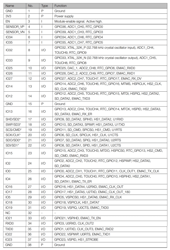
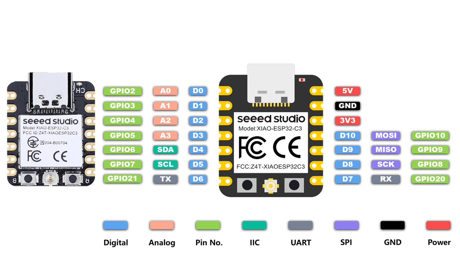
Seeed Studio XIAO ESP32C3 is an IoT mini development board based on the Espressif ESP32-C3 WiFi/Bluetooth dual-mode chip. ESP32-C3 is a 32-bit RISC-V CPU, which includes an FPU (Floating Point Unit) for 32-bit single-precision arithmetic with powerful computing power. It has excellent radio frequency performance, supporting IEEE 802.11 b/g/n WiFi, and Bluetooth 5 (LE) protocols. This board comes included with an external antenna to increase the signal strength for your wireless applications. It also has a small and exquisite form-factor combined with a single-sided surface-mountable design. It is equipped with rich interfaces and has 11 digital I/O that can be used as PWM pins and 4 analog I/O that can be used as ADC pins. It supports four serial interfaces such as UART, I2C and SPI. There is also a small reset button and a bootloader mode button on the board. XIAO ESP32C3 is fully compatible with the Grove Shield for Seeeduino XIAO and Seeeduino XIAO Expansion board except for the Seeeduino XIAO Expansion board, the SWD spring contacts on the board will not be compatible.
With regard to the features highlighted above, XIAO ESP32C3 is positioned as a high-performance, low-power, cost-effective IoT mini development board, suitable for low-power IoT applications and wireless wearable applications.
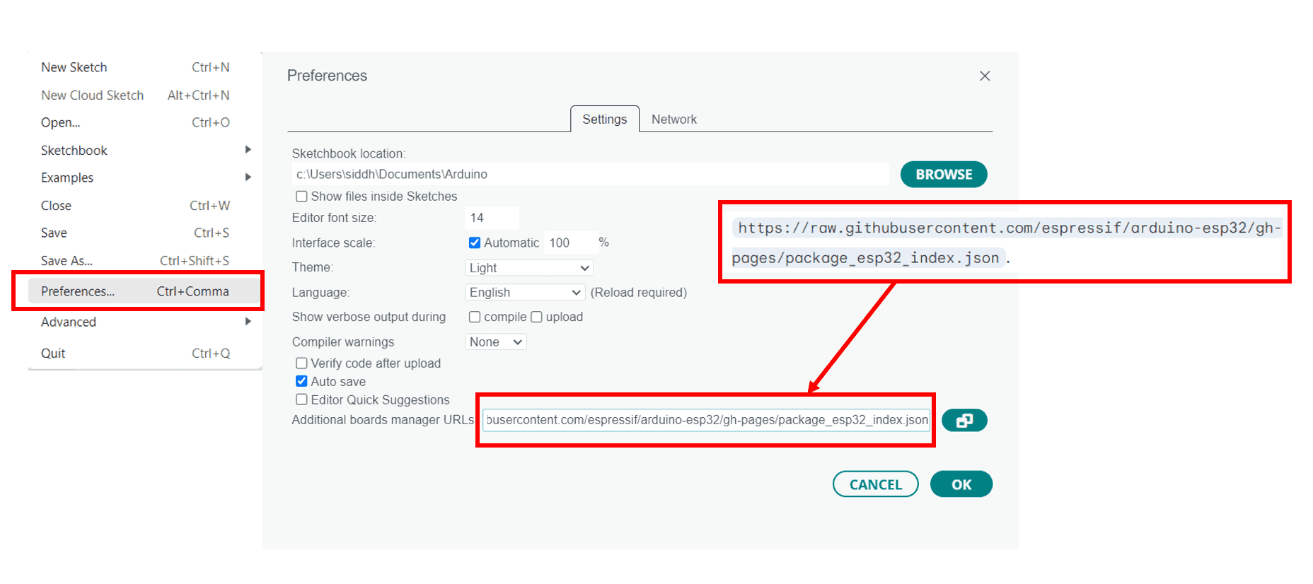
1. Open Arduino IDE --> Add ESP32 board package to Arduino IDE.
2. Navigate to File > Preferences, and fill "Additional Boards Manager URLs" with the url below:
https://raw.githubusercontent.com/espressif/arduino-esp32/gh-pages/package_esp32_index.json
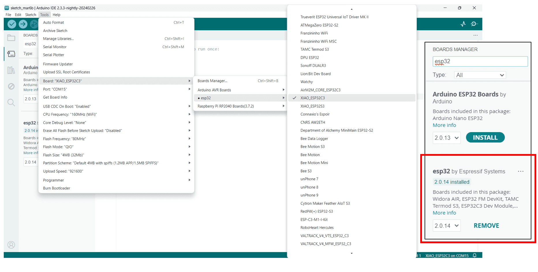
3. Go to Tools > Board > Boards Manager.
4. In Search Box Type ESP32 and by selecting the latest version install it.
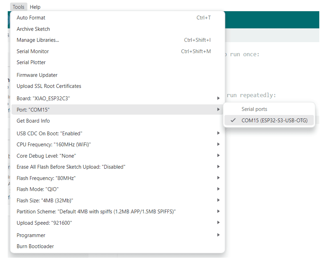
5. Select the Board and the Port(You can check the communication port from the Device Manager --> Ports)
6. Write the code --> Compile it --> Upload it in the board.
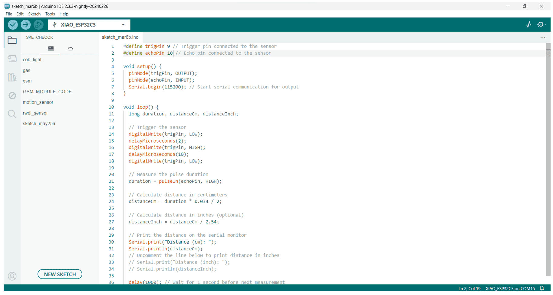

#define trigPin 2 // Trigger pin connected to the sensor
#define echoPin 4 // Echo pin connected to the sensor
void setup() {
pinMode(trigPin, OUTPUT);
pinMode(echoPin, INPUT);
Serial.begin(115200); // Start serial communication for output
}
void loop() {
long duration, distanceCm, distanceInch;
// Trigger the sensor
digitalWrite(trigPin, LOW);
delayMicroseconds(2);
digitalWrite(trigPin, HIGH);
delayMicroseconds(10);
digitalWrite(trigPin, LOW);
// Measure the pulse duration
duration = pulseIn(echoPin, HIGH);
// Calculate distance in centimeters
distanceCm = duration * 0.034 / 2;
// Calculate distance in inches
distanceInch = distanceCm / 2.54;
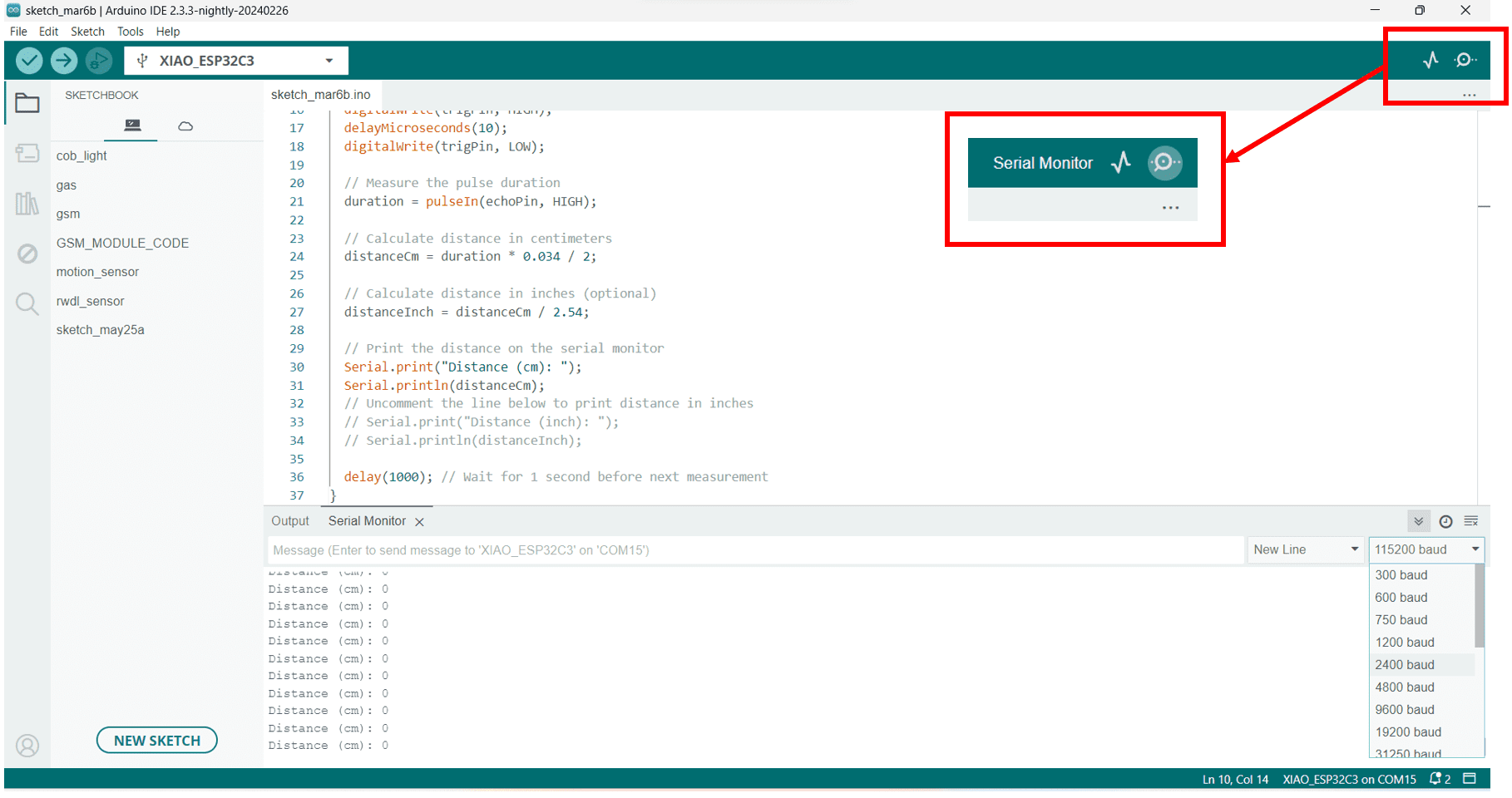
// Print the distance on the serial monitor
Serial.print("Distance (cm): ");
Serial.println(distanceCm);
// Uncomment the line below to print distance in inches
// Serial.print("Distance (inch): ");
// Serial.println(distanceInch);
delay(1000); // Wait for 1 second before next measurement
}