This week is going to be very interesting for me as it involves designing something, 3D printing it, and also characterizing the 3D printer we have in our lab. Additionally, I'll be scanning something on the 3D scanner and creating an STL file of that object to 3D print. It's going to be an exciting week for me, focusing on my area of interest.
This week, we focused on a group assignment centered around 3D scanning and printing. Our goal was to document our newfound knowledge about additive versus subtractive manufacturing, various 3D printing processes and materials, and the specifications of the 3D printer available in our Fab lab.
We detailed how we utilized the 3D printer for our group project, including the materials and tools we used, as well as the necessary precautions for safe operation. Additionally, we delved into the software required for generating G-code for the printer.
Our objectives for the assignment were as follows:
1. Gain a comprehensive understanding of additive manufacturing processes, including their types, materials, and tools.
2. Familiarize ourselves with the operation of the 3D printer.
3. Learn and implement safety precautions when using the machine.
4. Evaluate and test the design rules specific to our in-house 3D printer.
The Detailed information about the group assignment is on our Assignment Page.
1. Operate 3D Printing machine
2. Learn settings and safety precautions of the machine
3. Design and 3D print an object (small, few cm^3, limited by the printer time) that could not be made subtractively
4. 3D scan an object (and optionally print it)
3D printing or additive manufacturing is the construction of a three-dimensional object from a CAD model or a digital 3D model. It can be done in a variety of processes in which material is deposited, joined or solidified under computer control, with the material being added together (such as plastics, liquids or powder grains being fused), typically layer by layer.
3D printing is an additive technology used to manufacture parts. It is ‘additive’ in that it doesn’t require a block of material or a mold to manufacture physical objects, it simply stacks and fuses layers of material. It’s typically fast, with low fixed setup costs, and can create more complex geometries than ‘traditional’ technologies, with an ever-expanding list of materials. It is used extensively in the engineering industry, particularly for prototyping and creating lightweight geometries.
There are several types of 3D printing, which include:
Stereolithography (SLA)
Selective Laser Sintering (SLS)
Fused Deposition Modeling (FDM)
Digital Light Process (DLP)
Multi Jet Fusion (MJF)
PolyJet
Direct Metal Laser Sintering (DMLS)
Electron Beam Melting (EBM)
Selecting the right 3D printing process for your application requires an understanding of each process
strengths and weaknesses and mapping those attributes to your product development needs.
It’s safe to say 3D printing is most often used for prototyping. Its ability to quickly manufacture a single part enables product developers to validate and share ideas in a cost-effective manner. Determining the purpose of your prototype will inform which 3D printing technology will be the most beneficial. Additive manufacturing can be suitable for a range of prototypes that span from simple physical models to parts used for functional testing. Despite 3D printing being nearly synonymous with rapid prototyping, there are scenarios when it’s a viable production process. Typically these applications involve low-volumes and complex geometries. Often, components for aerospace and medical applications are ideal candidates for production 3D printing as they frequently match the criteria previously described.
Like most things in life, there’s rarely a simple answer when selecting a 3D printing process. When we assist customers evaluating their 3D printing options, we typically point to five key criteria to determine what technology will meet their needs:
1. Budget
2. Mechanical requirements
3. Cosmetic appearance
4. Material selection
5. Geometry
Stereolithography (SLA) is the original industrial 3D printing process. SLA printers excels at producing parts with high levels of detail, smooth surface finishes, and tight tolerances. The quality surface finishes on SLA parts, not only look nice, but can aid in the part’s function—testing the fit of an assembly, for example. It’s widely used in the medical industry and common applications include anatomical models and microfluidics. We use Vipers, ProJets, and iPros 3D printers manufactured by 3D Systems for SLA parts.
Selective laser sintering (SLS) melts together nylon-based powders into solid plastic. Since SLS parts are made from real thermoplastic material, they are durable, suitable for functional testing, and can support living hinges and snap-fits. In comparison to SL, parts are stronger, but have rougher surface finishes. SLS doesn’t require support structures so the whole build platform can be utilized to nest multiple parts into a single build—making it suitable for part quantities higher than other 3D printing processes. Many SLS parts are used to prototype designs that will one day be injection-molded. For our SLS printers, we use sPro140 machines developed by 3D systems.
PolyJet is another plastic 3D printing process, but there’s a twist. It can fabricate parts with multiple properties such as colors and materials. Designers can leverage the technology for prototyping elastomeric or overmolded parts. If your design is a single, rigid plastic, we recommend sticking with SL or SLS—it’s more economical. But if you’re prototyping an overmolding or silicone rubber design, PolyJet can save you from the need to invest in tooling early in the development cycle. This can help you iterate and validate your design faster and save you money.
Digital light processing is similar to SLA in that it cures liquid resin using light. The primary difference between the two technologies is that DLP uses a digital light projector screen whereas SLA uses a UV laser. This means DLP 3D printers can image an entire layer of the build all at once, resulting in faster build speeds. While frequently used for rapid prototyping, the higher throughput of DLP printing makes it suitable for low-volume production runs of plastic parts.
Similar to SLS, Multi Jet Fusion also builds functional parts from nylon powder. Rather than using a laser to sinter the powder, MJF uses an inkjet array to apply fusing agents to the bed of nylon powder. Then a heating element passes over the bed to fuse each layer. This results in more consistent mechanical properties compared to SLS as well as improved surface finish. Another benefit of the MJF process is the accelerated build time, which leads to lower production costs.
Fused deposition modeling (FDM) is a common desktop 3D printing technology for plastic parts. An FDM printer functions by extruding a plastic filament layer-by-layer onto the build platform. It’s a cost-effective and quick method for producing physical models. There are some instances when FDM can be used for functional testing but the technology is limited due to parts having relatively rough surface finishes and lacking strength.
Metal 3D printing opens up new possibilities for metal part design. The process we use at Protolabs to 3D print metal parts is direct metal laser sintering (DMLS). It’s often used to reduce metal, multi-part assemblies into a single component or lightweight parts with internal channels or hollowed out features. DMLS is viable for both prototyping and production since parts are as dense as those produced with traditional metal manufacturing methods like machining or casting. Creating metal components with complex geometries also makes it suitable for medical applications where a part design must mimic an organic structure.
Electron beam melting is another metal 3D printing technology that uses an electron beam that's controlled by electromagnetic coils to melt the metal powder. The printing bed is heated up and in vacuum conditions during the build. The temperature that the material is heated to is determined by the material in use.
As stated earlier, there are a couple common denominators among 3D printing applications. If your part quantities are relatively low, 3D printing can be optimal—the guidance we give our 3D printing service customers is usually 1 to 50 parts. As volumes start to near the hundreds, it’s worth exploring other manufacturing processes. If your design features complex geometry that is critical to your part’s function, like an aluminum component with an internal cooling channel, 3D printing might be your only option. Selecting the right process comes down to aligning the advantages and limitations of each technology to your application’s most important requirements. In the early stages when ideas are being thrown around and all you need is a model to share with a colleague, those stair-stepping surface finishes on your part aren’t of much concern. But once you hit the point where you need to conduct user testing, factors like cosmetics and durability start to matter. Although there is no one-size-fits-all solution, properly utilizing 3D printing technology throughout product development will reduce design risk and, ultimately, result in better products.
Sanjivani Fab Lab owns Creality CR5PRO 3D printing machine. I wanted to print 3D printed fabric. Basically, 3D printing fabric is a technology that can create designs and optical effects on garments, footwear and accessories. 3D printed fabric has a positive environmental impact because it generates minimal waste and uses only the neccessary amount of material. Specially, flexible materials or biodegradable, recyclable polymers such as TPU-Thermoplastic Polyurethane, which is a type of plastic that has properties of both rubber and plastic. But I have used PLA material which was the only available material.
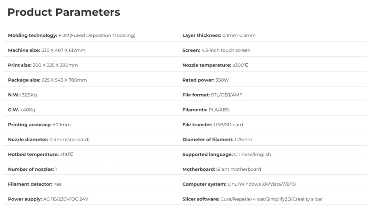
Here are some specifications of Creality CR5PRO 3D printing machine based on its architecture, usage, storage and communication.
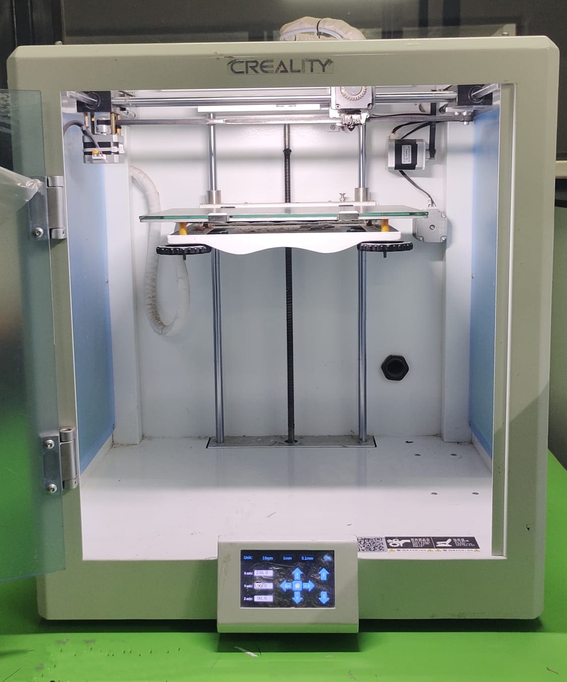
Here is the picture of Creality CR5PRO 3d printer situated at Sanjivani Fab Lab. Basically, 3D printer consist of sections such as bed, nozzle, control monitor, SD Card Port, on-off switch, material section, etc. Bed is used to place the object to be printed and nozzle is used to extract melted material to print coded object. Chip port is used to insert chip which has converted GCode file.
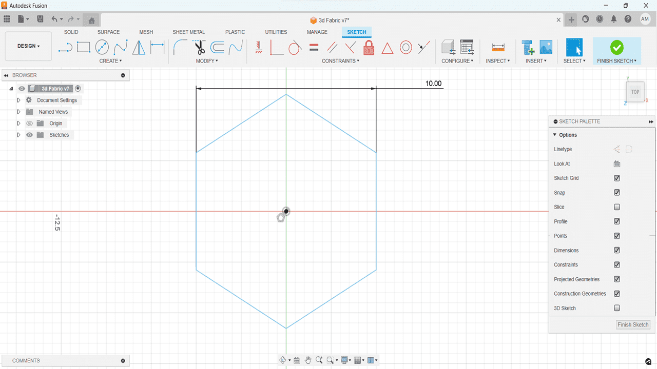
Firstly, to draw rough geometric design of a fabric, I have selected Top plane. Then I used "Polygon-Circumscribed polygon" command to draw Hexagonal fabric shape. It creates polygon using the center point and the midpoint of one edges.Resize the hexagon by going to sketch, Sketch dimension and click on two opposite sides of the hexagon and drag the measuring tool out. Now, go to "Extrude" feature and click on the hexagon to extrude it. Extrude is basically used to adds depth to a closed sketch profile or planar face.
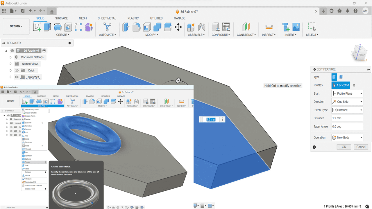
Now, go to "Torus" feature to create a solid body sphere.
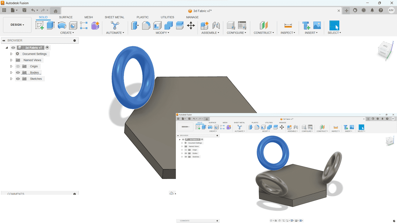
Click on the Torus and go to Modify, click on Move/Copy command to rotate wheel in -90 degrees. Place the torus on the exact position as per our need using rotation feature. Now we have got one Torus, we can create a pattern to draw the rest of the entities automatically.
To create respective circular pattern along respective plane, go to circular pattern feature available in pattern option. Draw circle with specified diameter and again used circullar pattern feature.
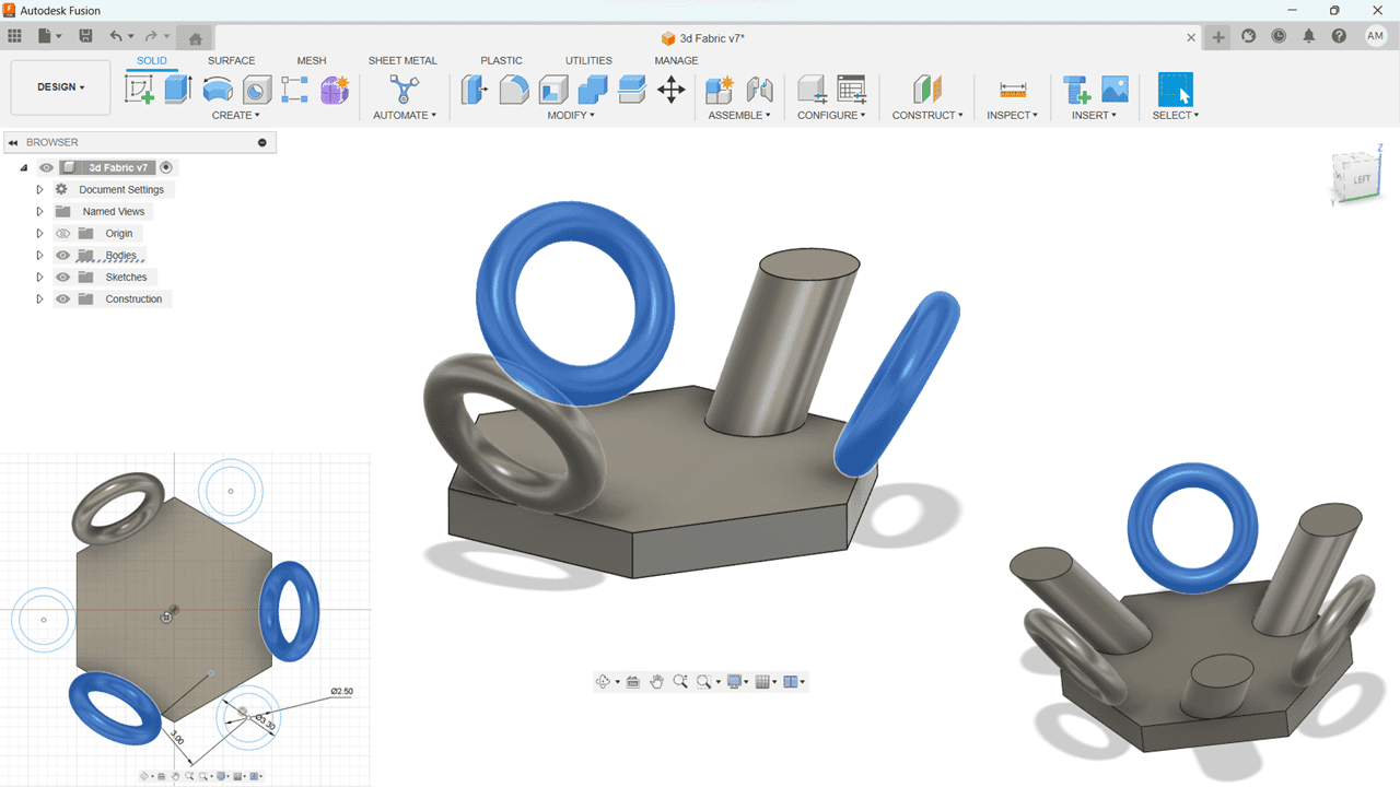
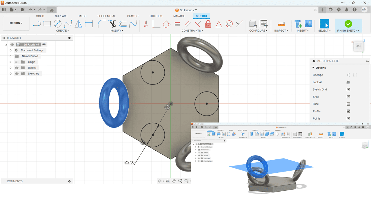
Now, add offset plane using construct offset plane feature. Construct a center circle along the constructed offset plane which is parallel with existing constructed plane.
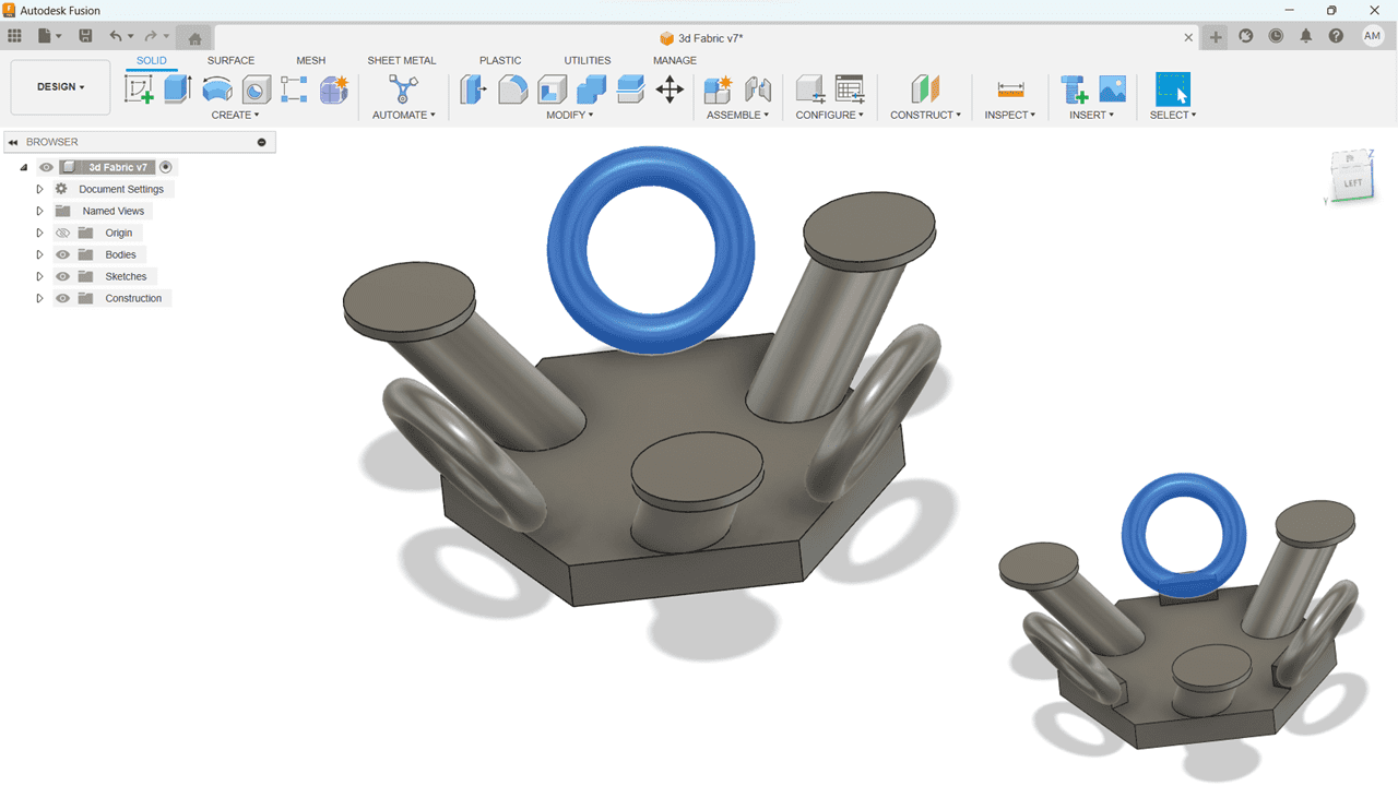
To make the poles along both the plane, I have used "Loft" feature on two selected circles from existing as well as constructed offset plane. Now, create a new sketch on the surface of one of the poles and draw center diameter circle. Finally, the sketch of one part is ready.
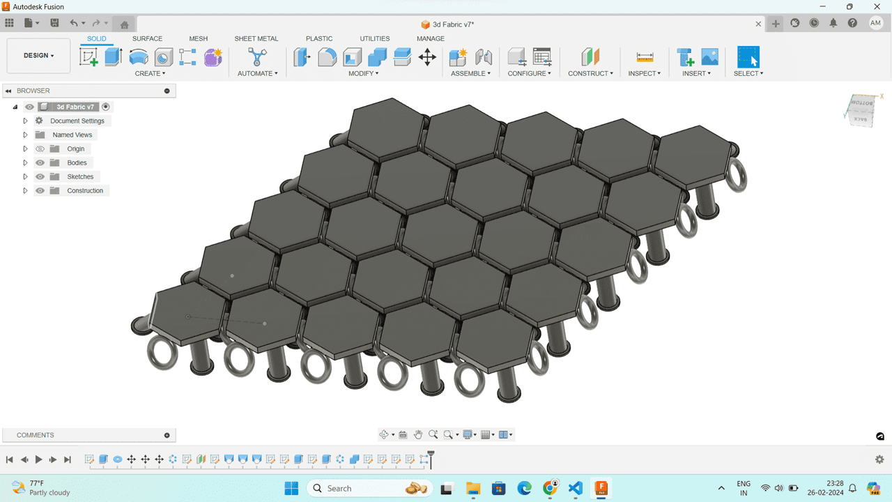
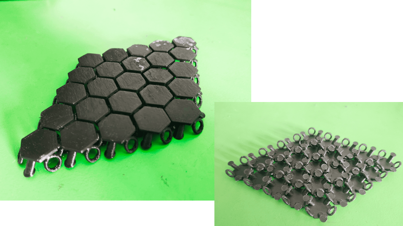
Now, I wanted to make a complete piece of fabric using "Pattern" command.
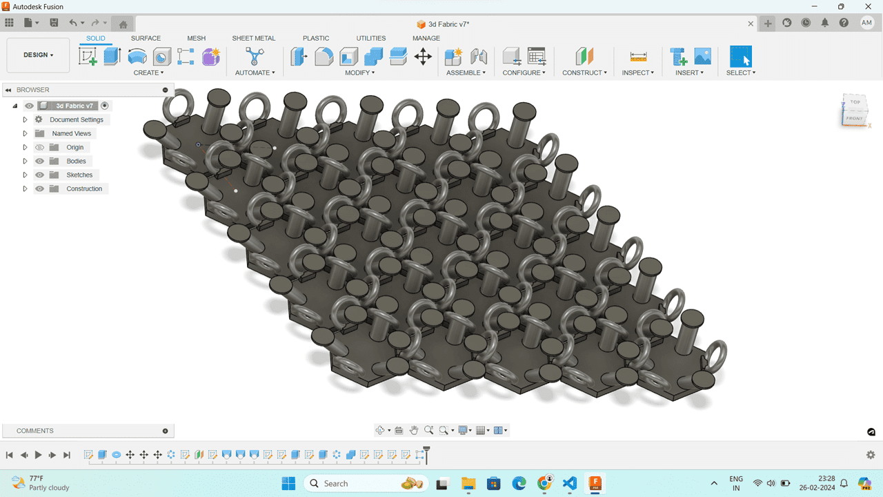
Here is the final picture of complete assembled 3D printed fabric.
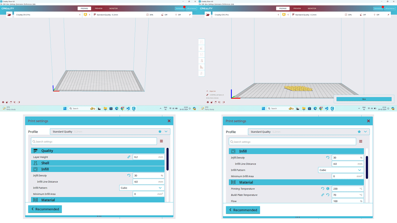
After that, I exported the model in .stl format and used the Creality slicer for generating the G-code. Here's the interface of the Creality software: I set the infill for this model at 25% and used PLA material. So, I adjusted the bed temperature to 70 degrees Celsius and the nozzle temperature to 230 degrees Celsius for proper material melting and smooth 3D printing.
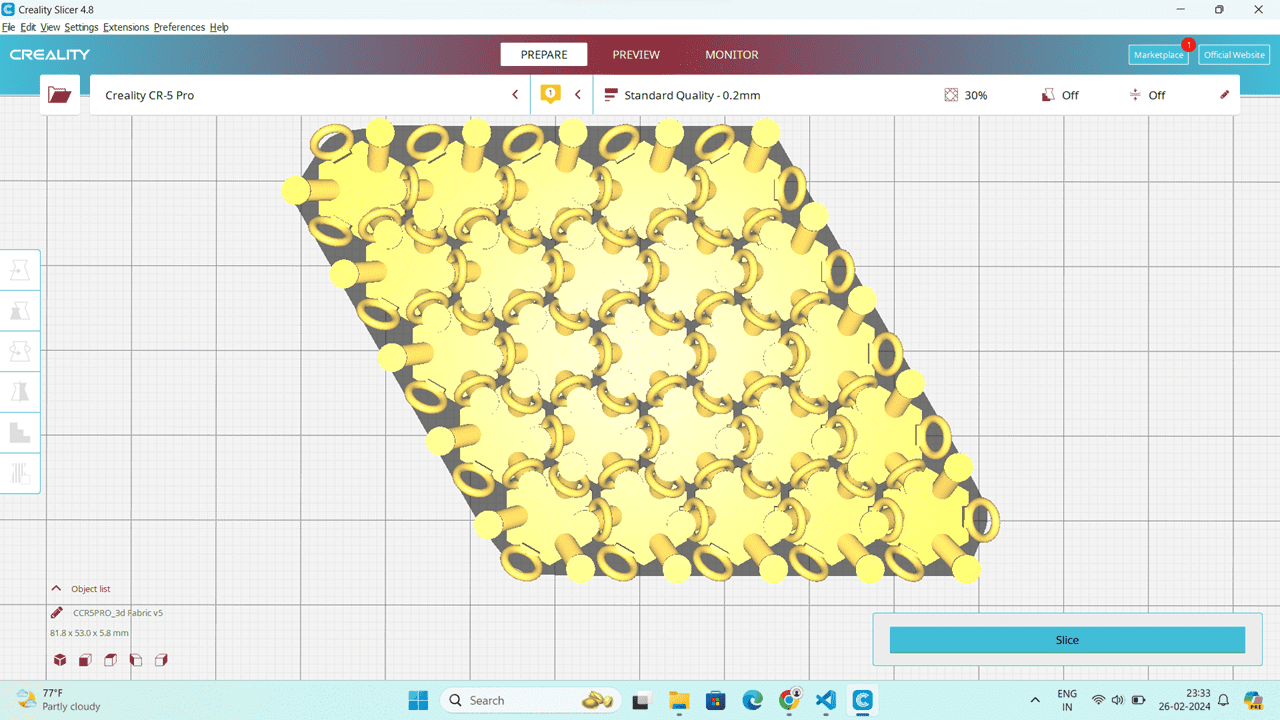
Then, I imported the model using the CTRL + O option and clicked on "slice" for generating the G-code. After the completion of the process, I copied the file to the SD card to insert it into the machine.
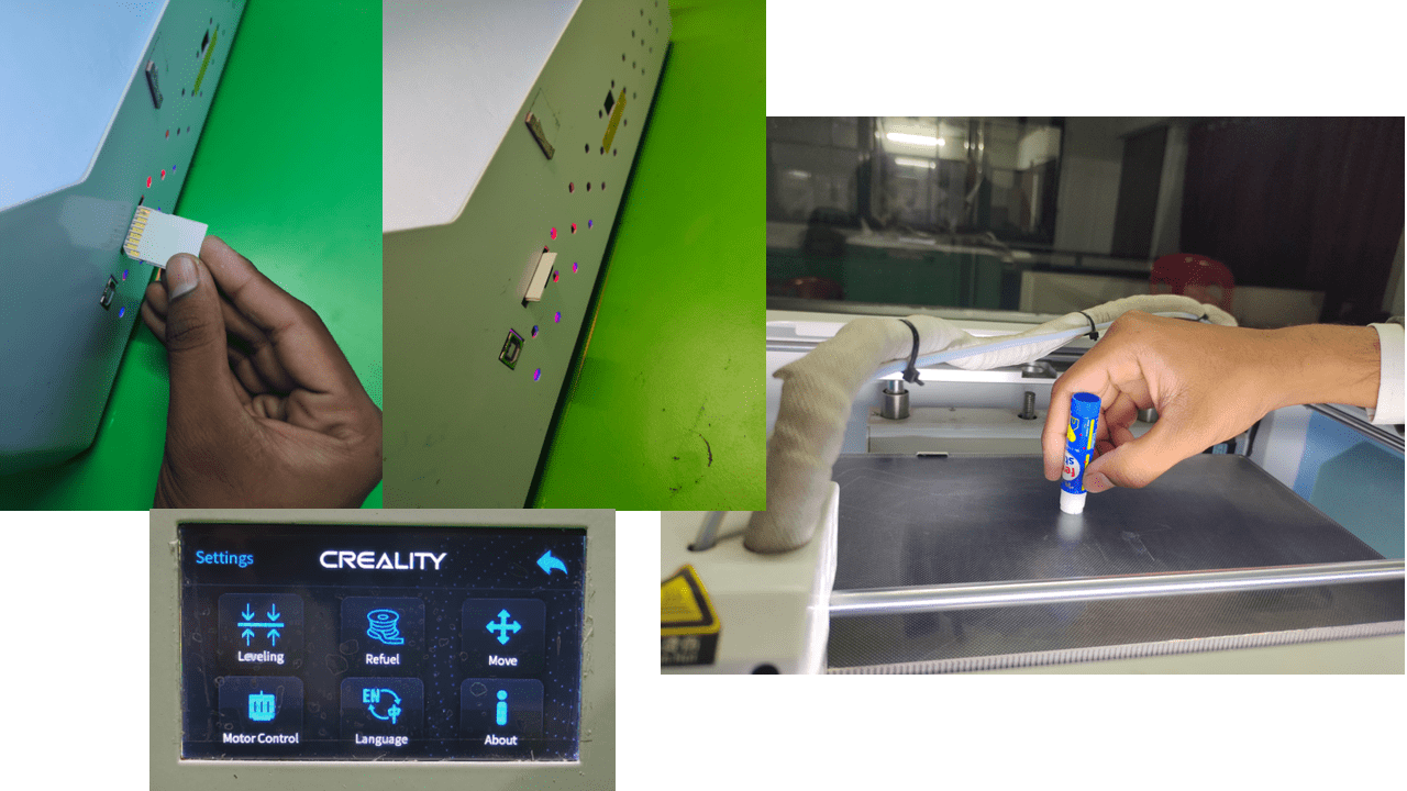
I inserted the SD card into the machine and leveled the bed using the auto bed leveling option. After that, I applied some glue to the surface of the 3D printer bed. This helps in easily removing or separating the object from the bed after printing is completed.
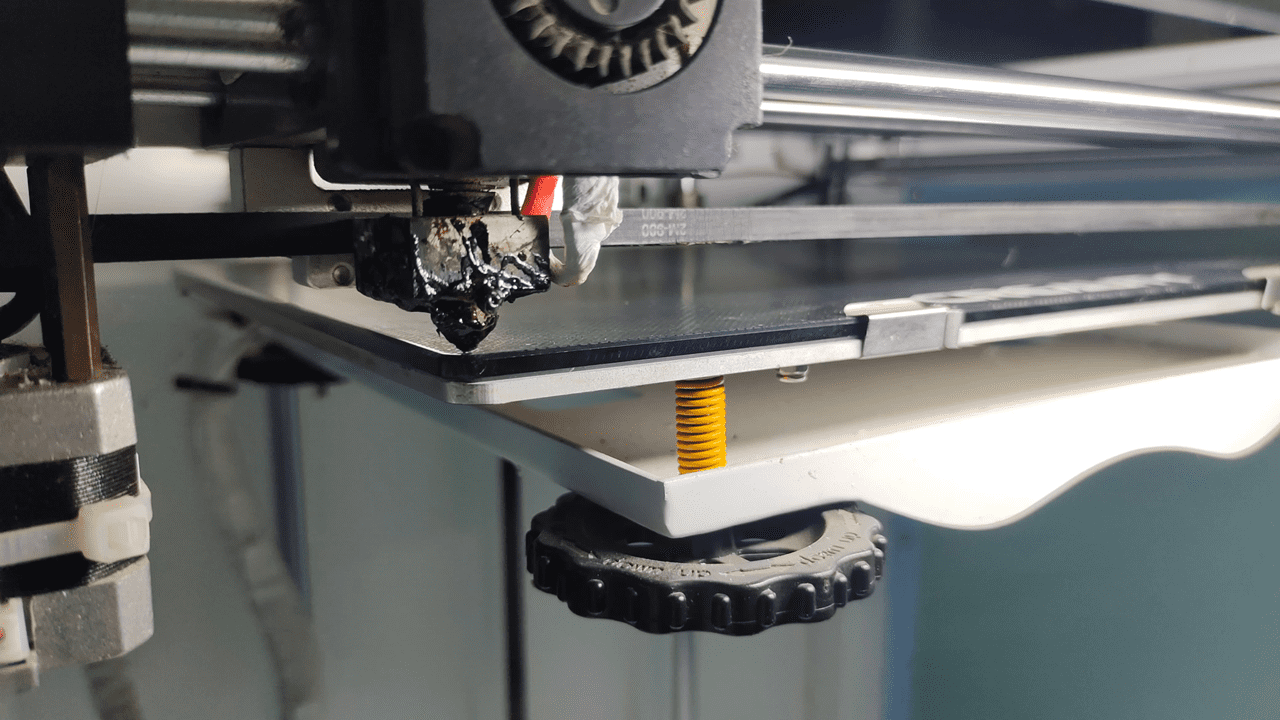
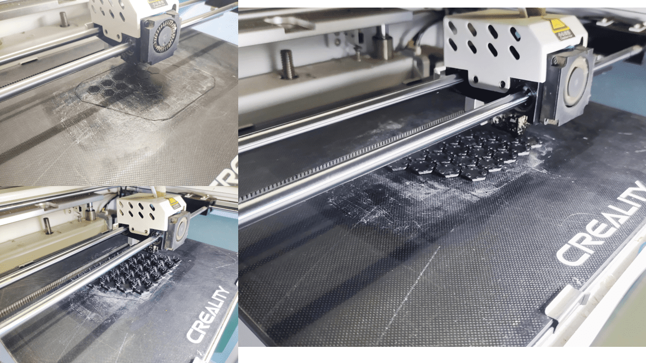
These are the photos of the first layer of the 3D printing process, showing how it looks at the beginning.
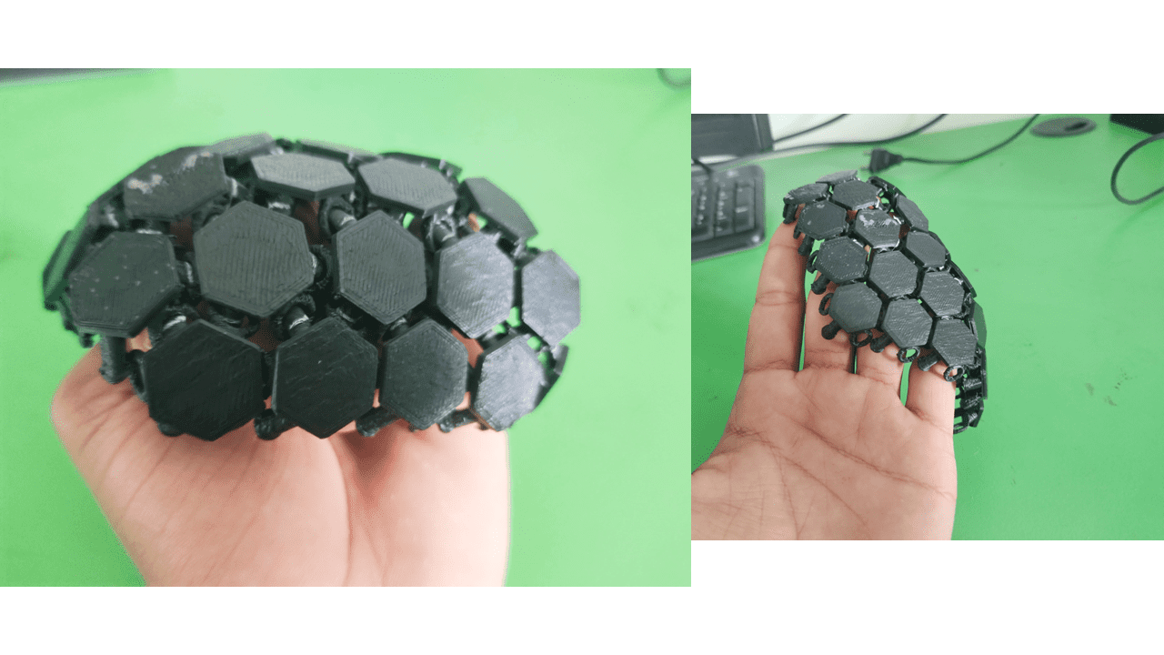
This is my final output, and it is working properly as needed. It behaves like a fabric, capable of bending on uneven surfaces.
3D Scanning is the process by which we can make the digital 3D models of the real world objects. It involves the Analysis of object that is it's shape and size and appearence to generate the 3D model or the Digital Replica of the object.
3D Scanning Process: a. Projecting a light source onto a material. b. Digitizing the millions of points of photographic processing from the reflected light. c. Fusing the multiple snapshots of an object into a 3D model.
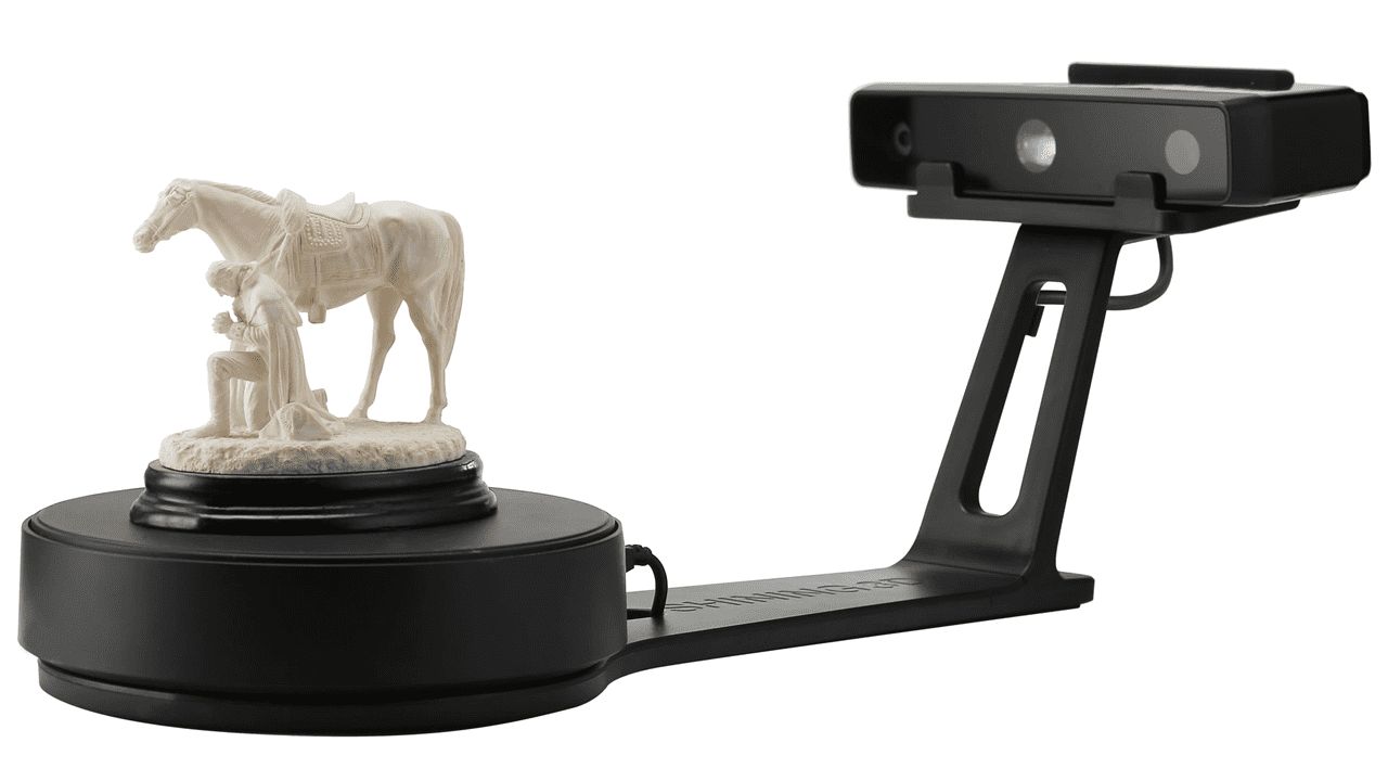
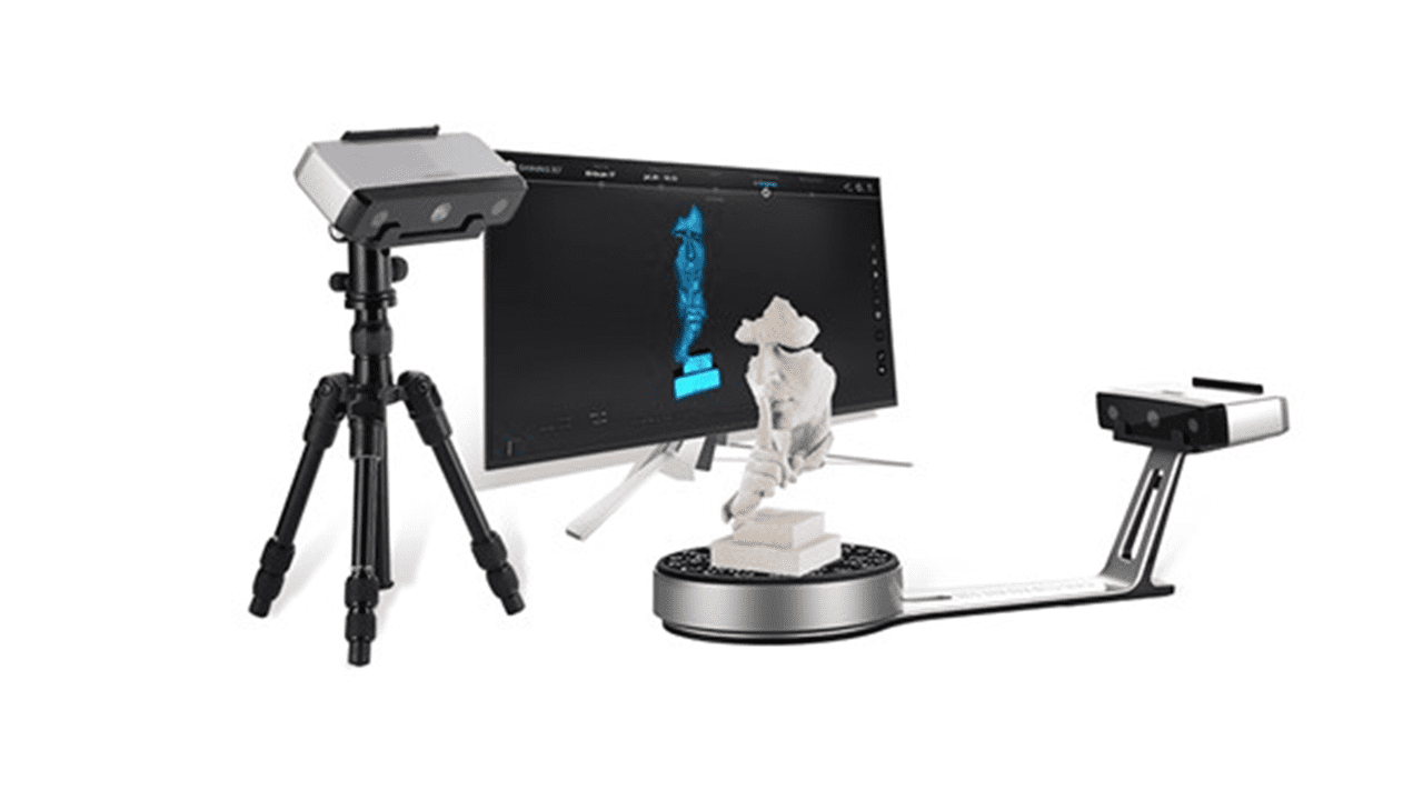
I am going to use the EinScan-SP 3D Scanner for this task.
KEY features of EinScan-SP
-Capturing 3D Data Easier and Faster.
-Easy Operation & Fast Scanning Speed.
-Certified Accuracy.
-Compatible with 3D Printers.
-Enables Reverse Engineering & Design in the Office.
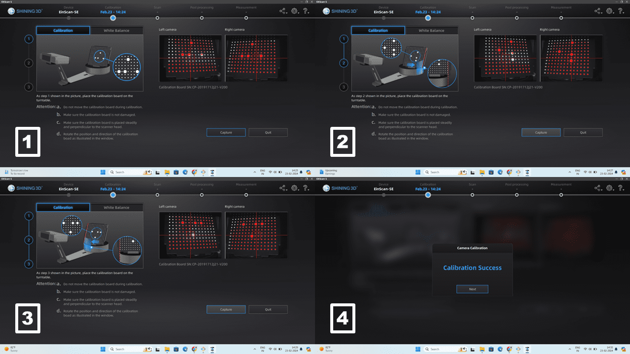
Firstly, I completed the calibration of the scanner using the calibration board.
calibration:
Step 1: As seen in the photo, you need to place the calibration board on the support with the 3 large points on the board facing down. Then click on "Capture".
Step 2: In this step, turn the calibration board so that the 3 large dots are facing to the right. Then bring them closer together so that the end of the dotted area and the end of the rotating table are aligned.
Step 3: The last step is like the second step, do the same to the left side. The 3 large dots should be set facing up at this step.
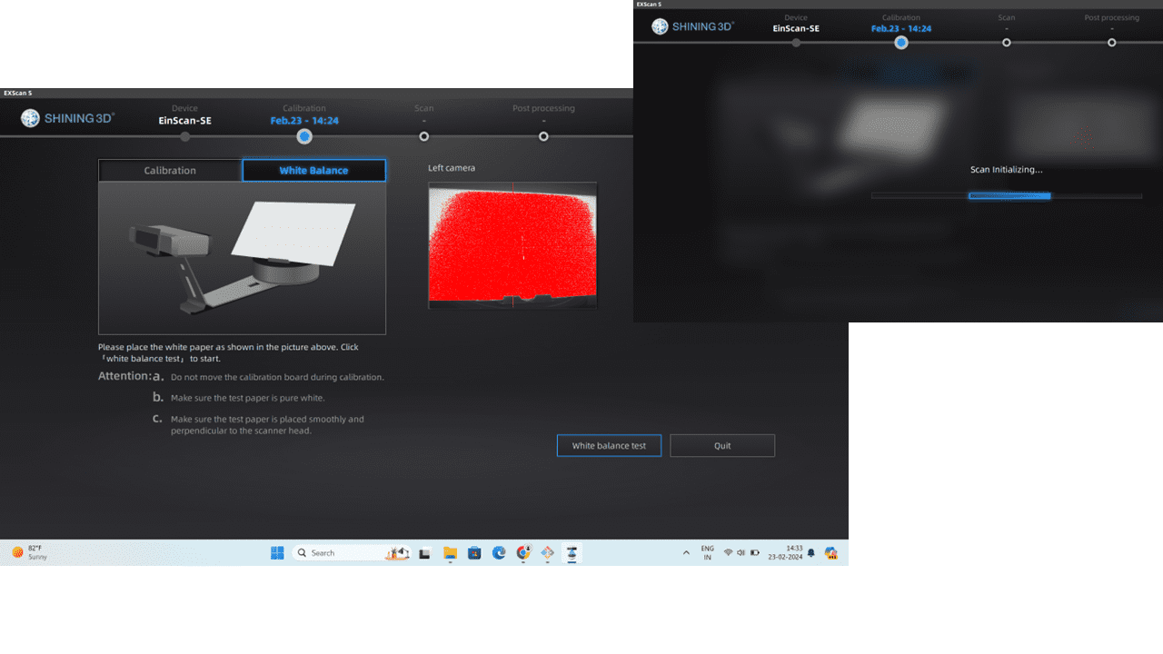
Step 4: After a successful calibration, white balancing should also be done. You need to completely turn the calibration board and capture over the white surface.
Now we are ready to go and start your scans.
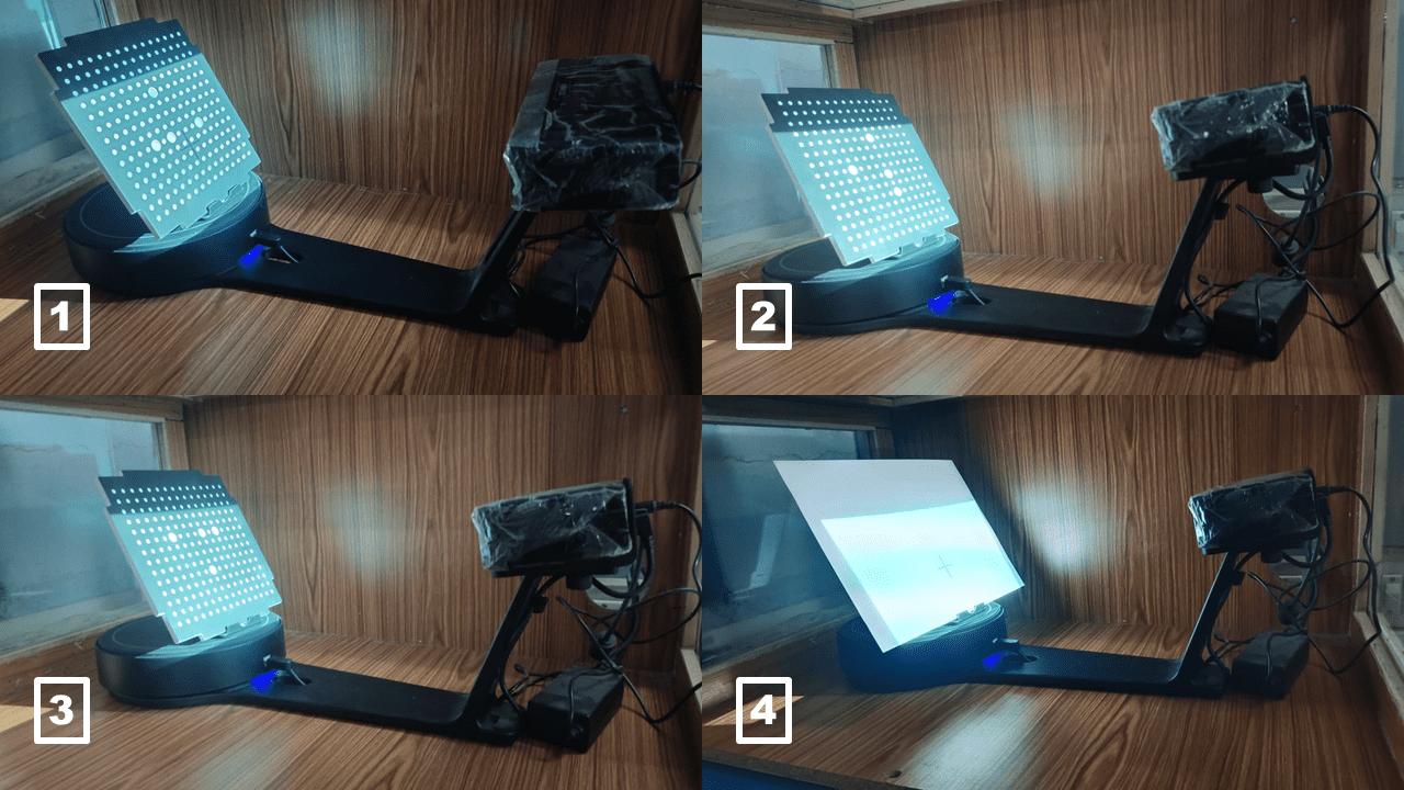
These are some real and live photographs of the calibration test that I conducted before the scanning.
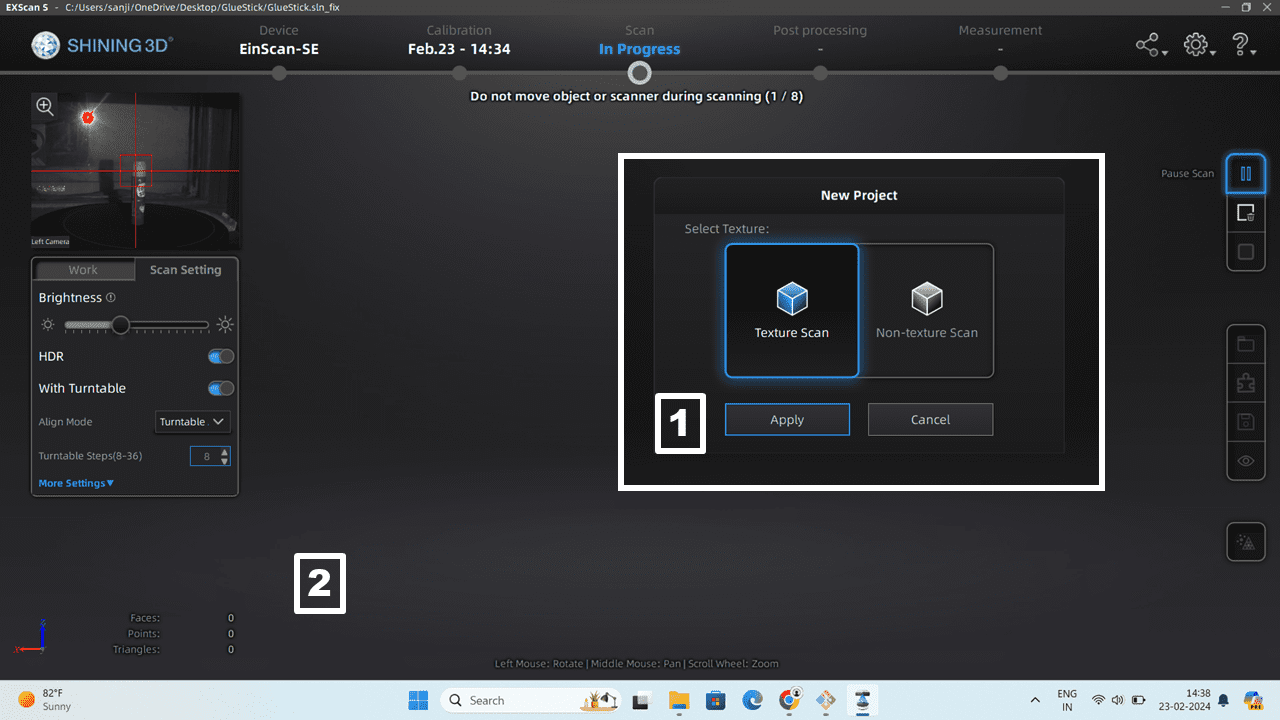
After the calibration test, we will be redirected to the next window where we have to select the "New Project." In it, two options are available: 1. Texture Scan & 2. Non-Texture Scan.
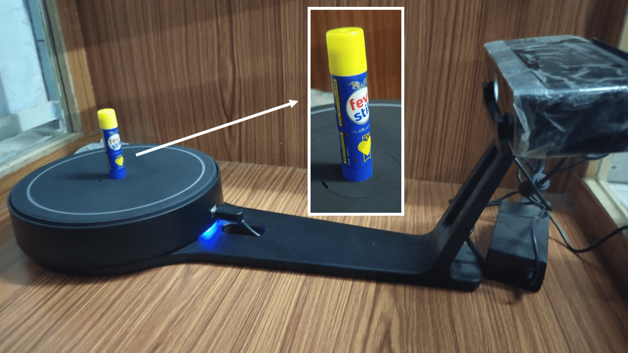
I placed a glue stick as an object in the scanner for 3D scanning.
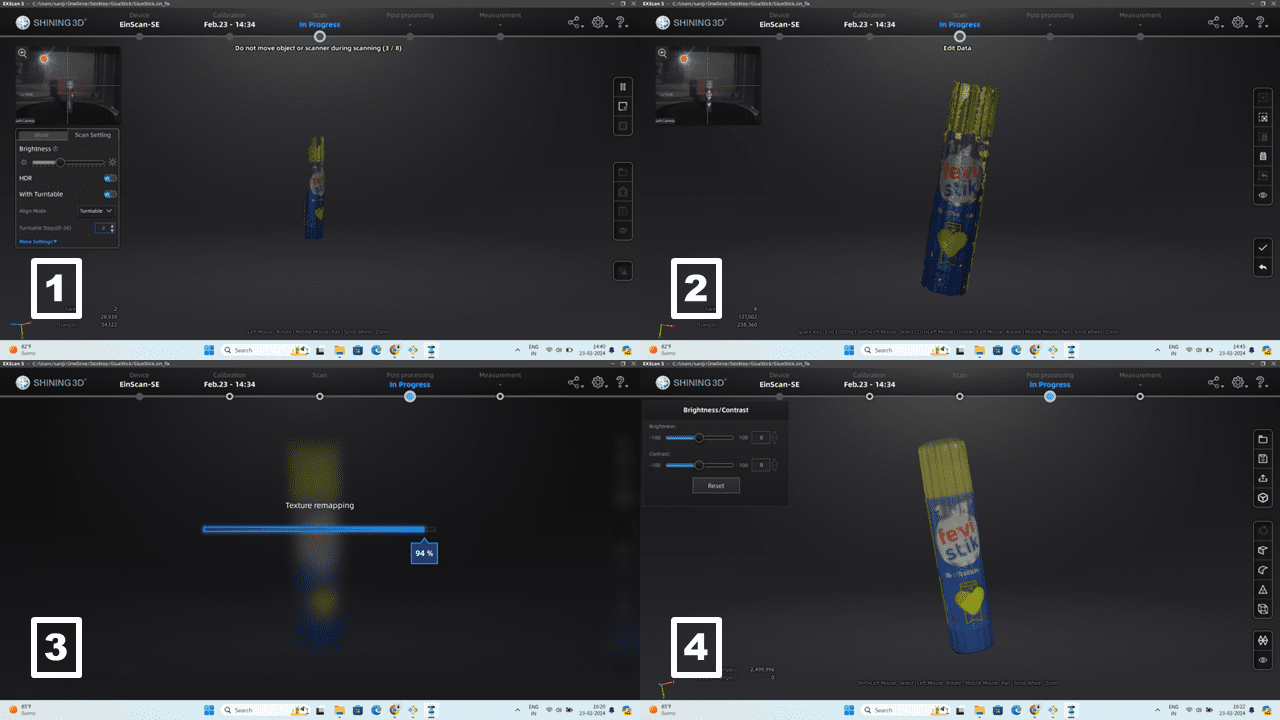
These are some results I obtained from the scanning. It takes time to scan the object, and we can set the number of rotations for the precision of the 3D model. I have taken 32 steps for the scanning, so it will take more time, but we will get more details. After that, we have to save the file as .obj or .stl for 3D printing. I have saved the file as an .stl file.
Additionally i scan my own face on the 3D Scanner app and maked the 3D model of it using i pad
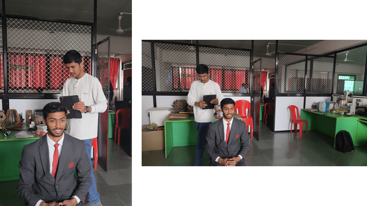
I scanned myself using the iPad as part of my assignment.
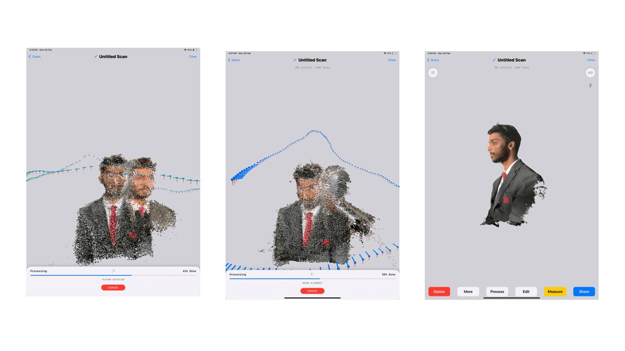
These are rendering screenshots on the iPad for creating a 3D model, which we can export in various formats such as .obj or .stl. Additionally, we can directly upload it to Sketchfab using the app.
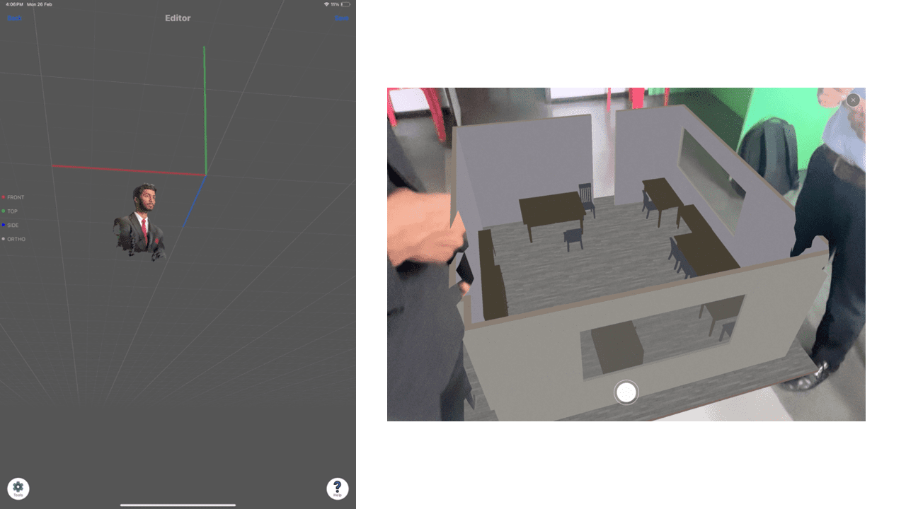
Along with my model, I also attempted to scan our Fab Lab, and you can see the result above. The software only detected the large square or rectangular objects. We can measure the actual length of the object, which is not extremely precise but is close to accurate.
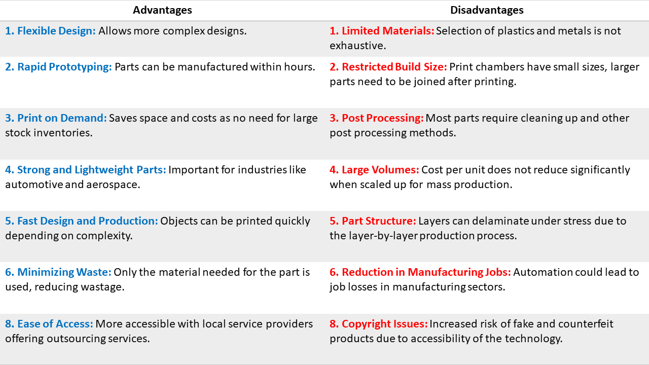
Types of 3D Printing Technology
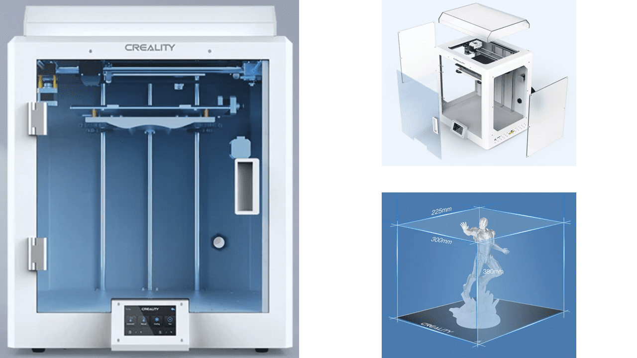
3D Printer - CR5 Pro
3D Scanner - EinScan-SP
EinScan-SP Calibration Tutorial