This week presented a series of challenges and complexities. I'm finding it difficult to articulate the specifics.
1. Individual assignment:
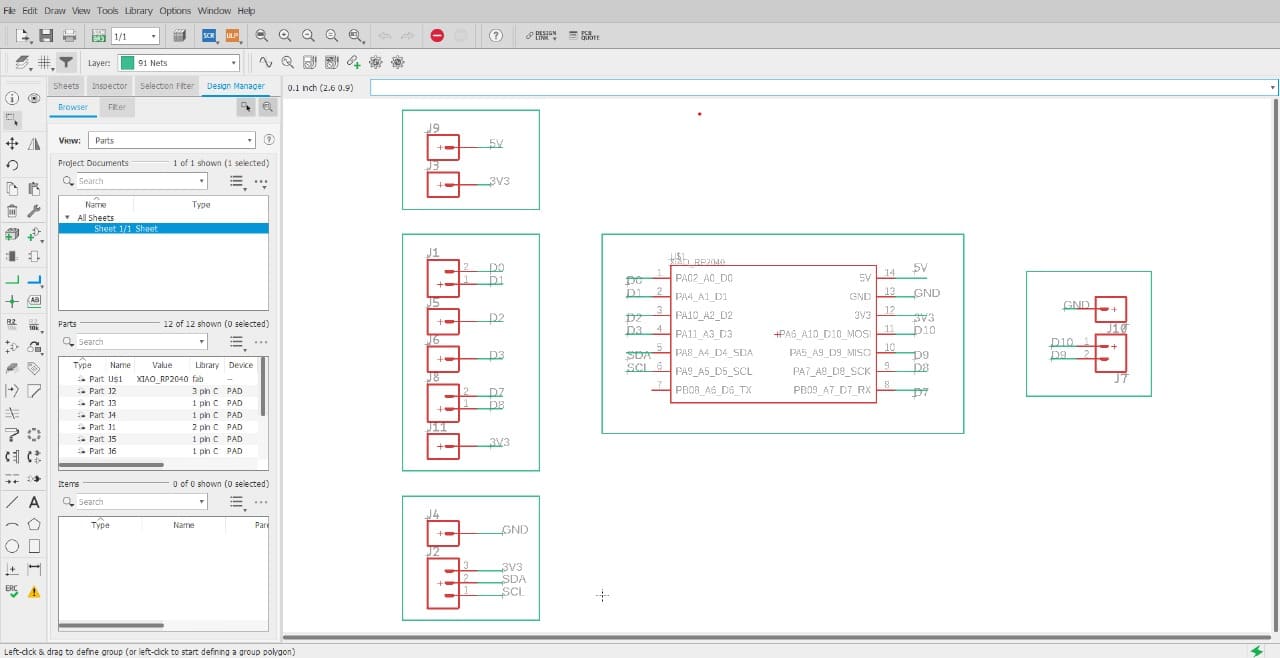
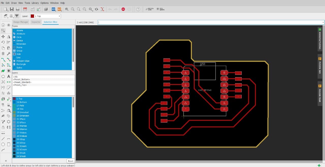
Design and document the system integration for your final project
        #define button1 D0

        #define button2 D1

        #define button3 D2

        #define button4 D3

        #define led D10


        #define input1 D7

        #define input2 D8

        int mode = 0;


        bool state1;

        bool state2;

        bool state3;

        bool state4;


        bool input1_state ;

        bool input2_state ;


        void setup() {

          pinMode(led,OUTPUT);

          pinMode(button1,INPUT_PULLDOWN);

          pinMode(button2,INPUT_PULLDOWN);

          pinMode(button3,INPUT_PULLDOWN);

          pinMode(button4,INPUT_PULLDOWN);

          pinMode(input1,INPUT_PULLDOWN);

          pinMode(input2,INPUT_PULLDOWN);

          Serial.begin(9600);

        }


        void loop() {


        state1 = digitalRead(button1);

        state2 = digitalRead(button2);

        state3 = digitalRead(button3);

        state4 = digitalRead(button4);

        input1_state = digitalRead(input1);

        input2_state = digitalRead(input2);

          if(state1 == HIGH)

          {

            mode = 1;

            Serial.println("mode1");

          } else if ( state3 == HIGH)

          {

            mode = 3;

            Serial.println("mode3");

          } else if ( state2 == HIGH)

          {

            Serial.println("mode2");

            mode = 2;

          } else if ( state4 == HIGH)

          {

            Serial.println("mode4");

            mode = 4;

          }

        Serial.println(mode);

        switch(mode) {

          case(1):

          digitalWrite(led,(input1_state && input2_state));

          Serial.println("and");

          break;

          case(2):

          digitalWrite(led,(input1_state || input2_state));

          Serial.println("or");

          break;

          case(3):

          digitalWrite(led,!(input1_state && input2_state));

          Serial.println("nand");

          break;

          case(4):

          digitalWrite(led,!(input1_state || input2_state));

          Serial.println("nor");

          break;

          default :

          Serial.println("press input buttons");

          break;

          Serial.println(mode);

        }


        }
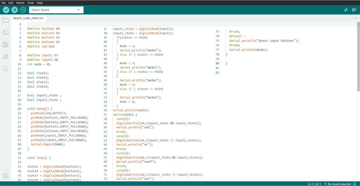
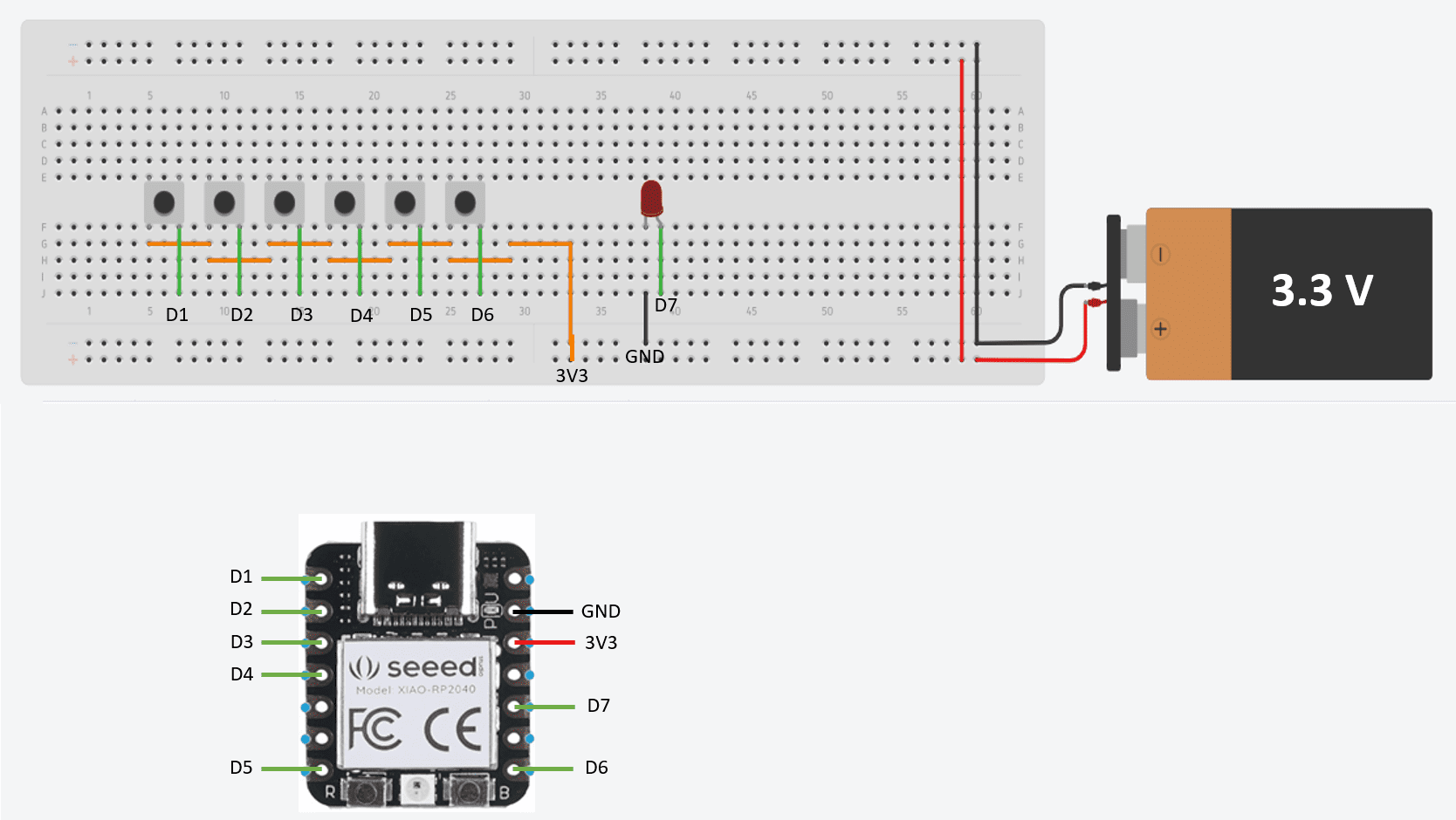
I was facing difficulties while interfacing tatile push buttons with Xiao RP2040, When I just touch the Button then it automatically shows high signal, I didn't used the pull up or pull down resistors because of this reason this was happned and I didn't got the proper output for logic gates.
I made changes in my code in such a way that,
void setup() {
pinMode(led,OUTPUT);
pinMode(button1,INPUT_PULLDOWN);
pinMode(button2,INPUT_PULLDOWN);
pinMode(button3,INPUT_PULLDOWN);
pinMode(button4,INPUT_PULLDOWN);
pinMode(input1,INPUT_PULLDOWN);
pinMode(input2,INPUT_PULLDOWN);
Serial.begin(9600);
}
I Pulldown the input in code and then again uploded the code in RP2040, Then I worked properly.
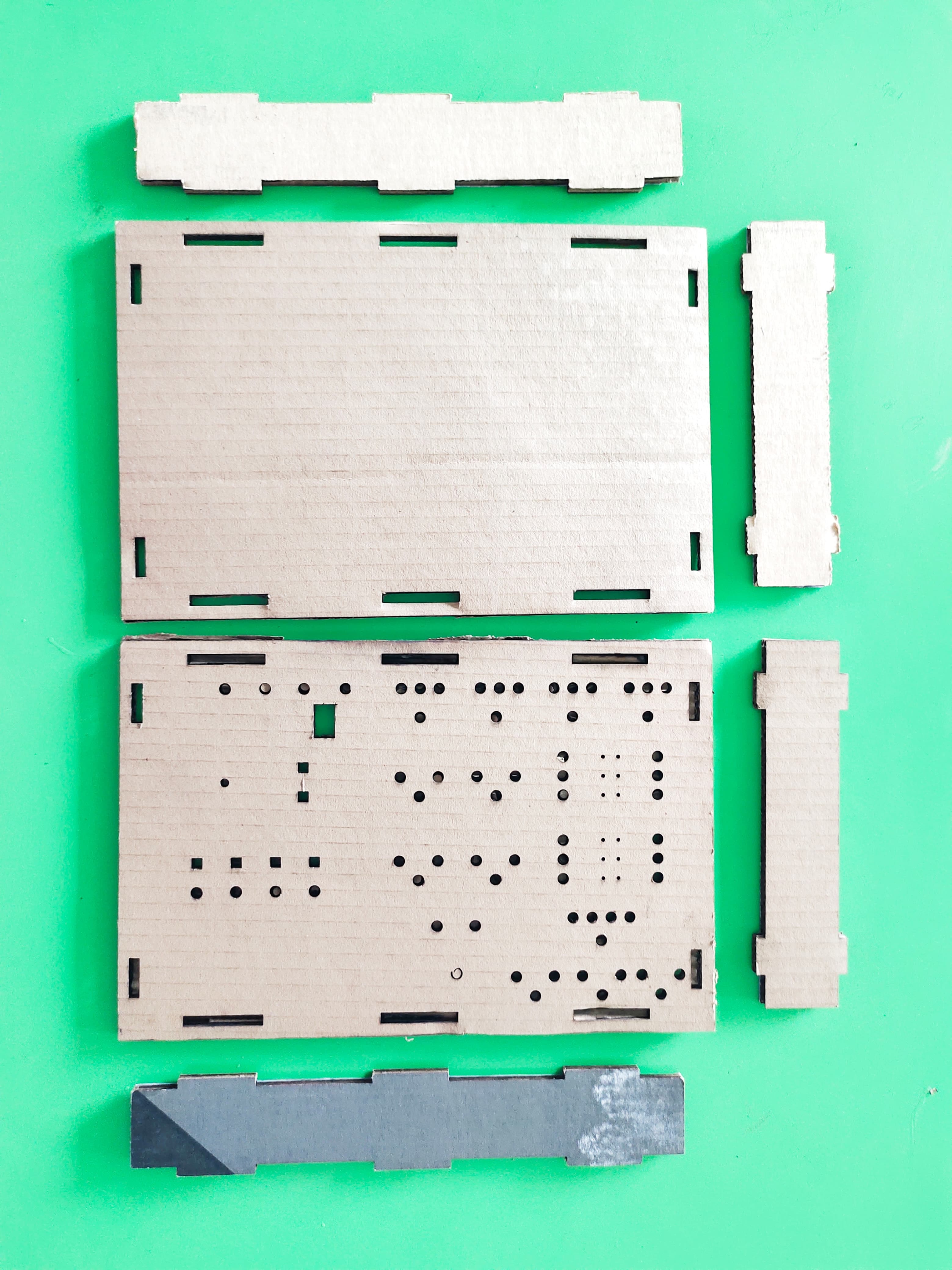
After that I Designed the Electronics Learning Kit Box using SolidWorks
This is the Casing of my Electronics Learning kit.
After that I Laser Cutted the Parts of Box, in which I exported the DXF Files of Box into the LaserCAD software, and I cutted all the parts.
After Laser Cutting I got this Output
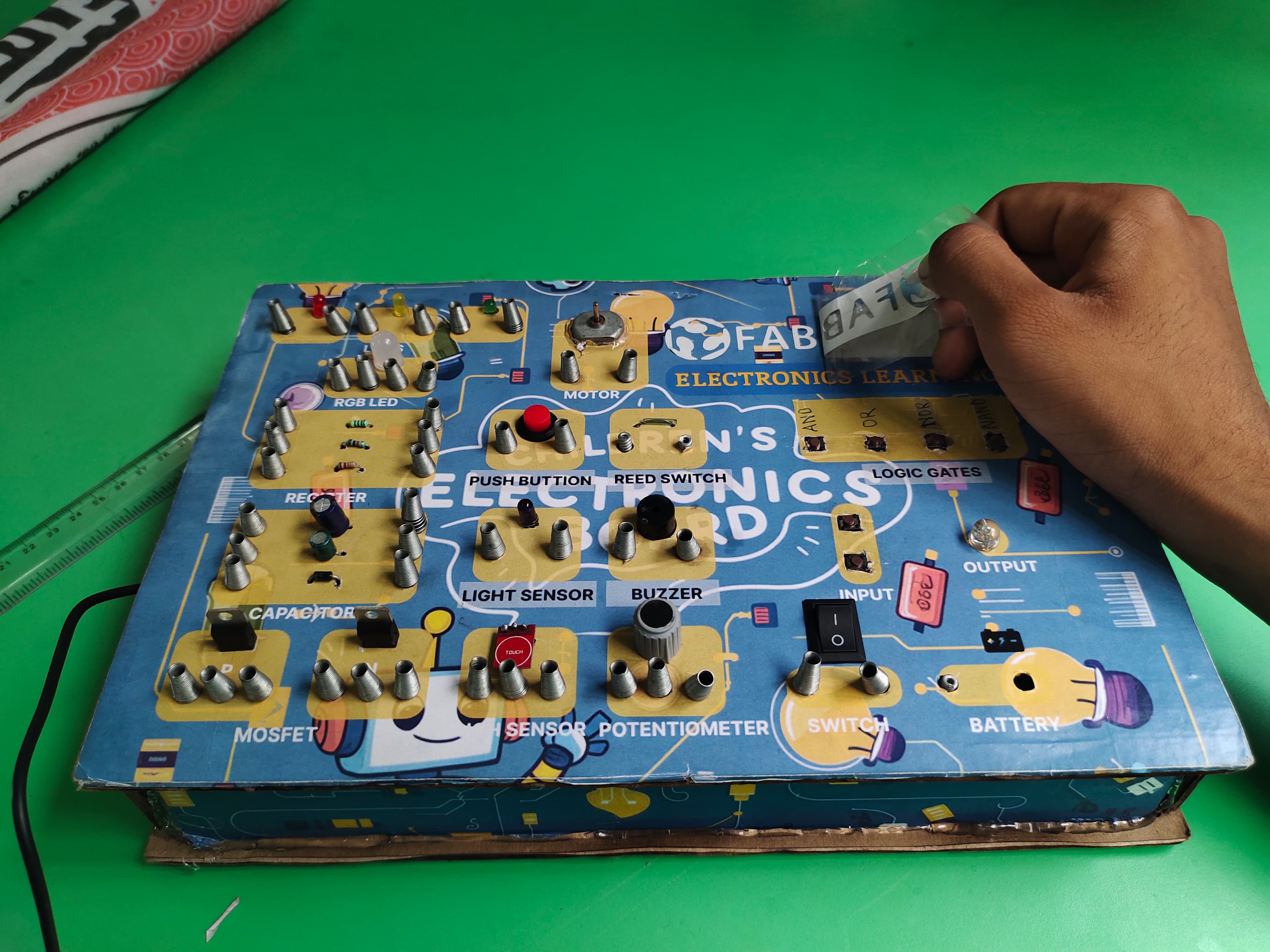
This is the poster that I have designed using Figma, I used Multiple layers option, Different shapes and the background image which is generated by Ideogram by chatgpt.
I sticked that poster onto my final kit box.
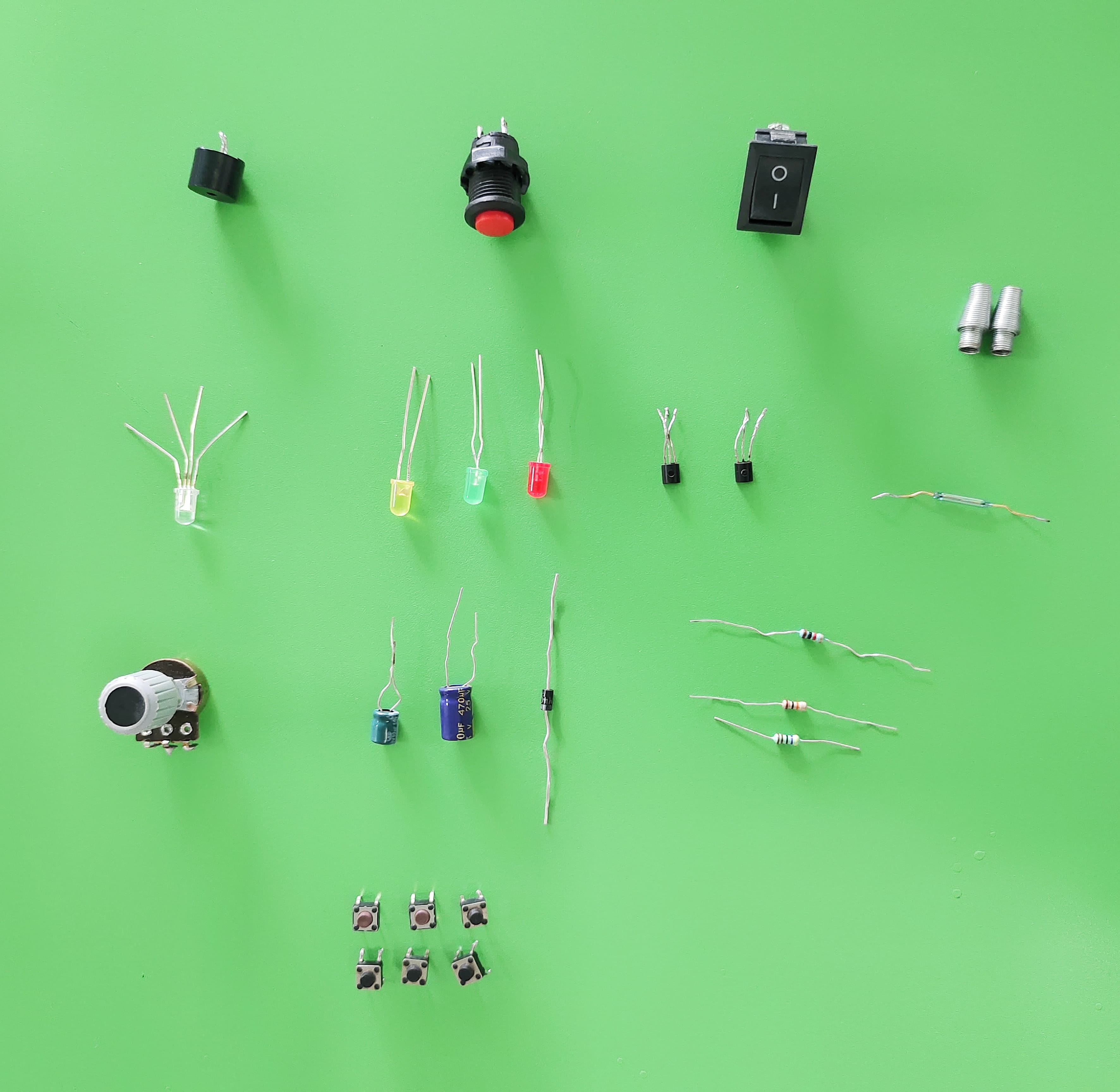
Components
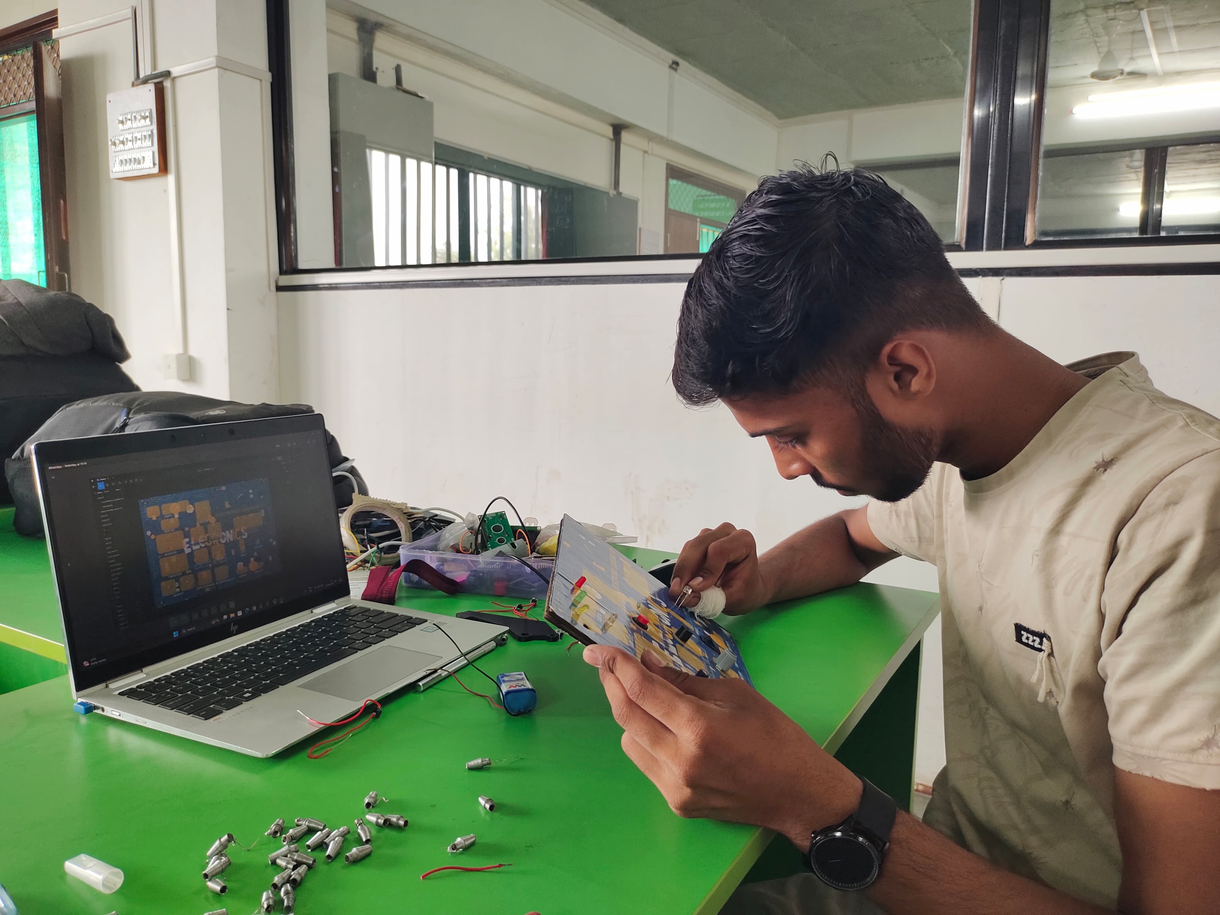
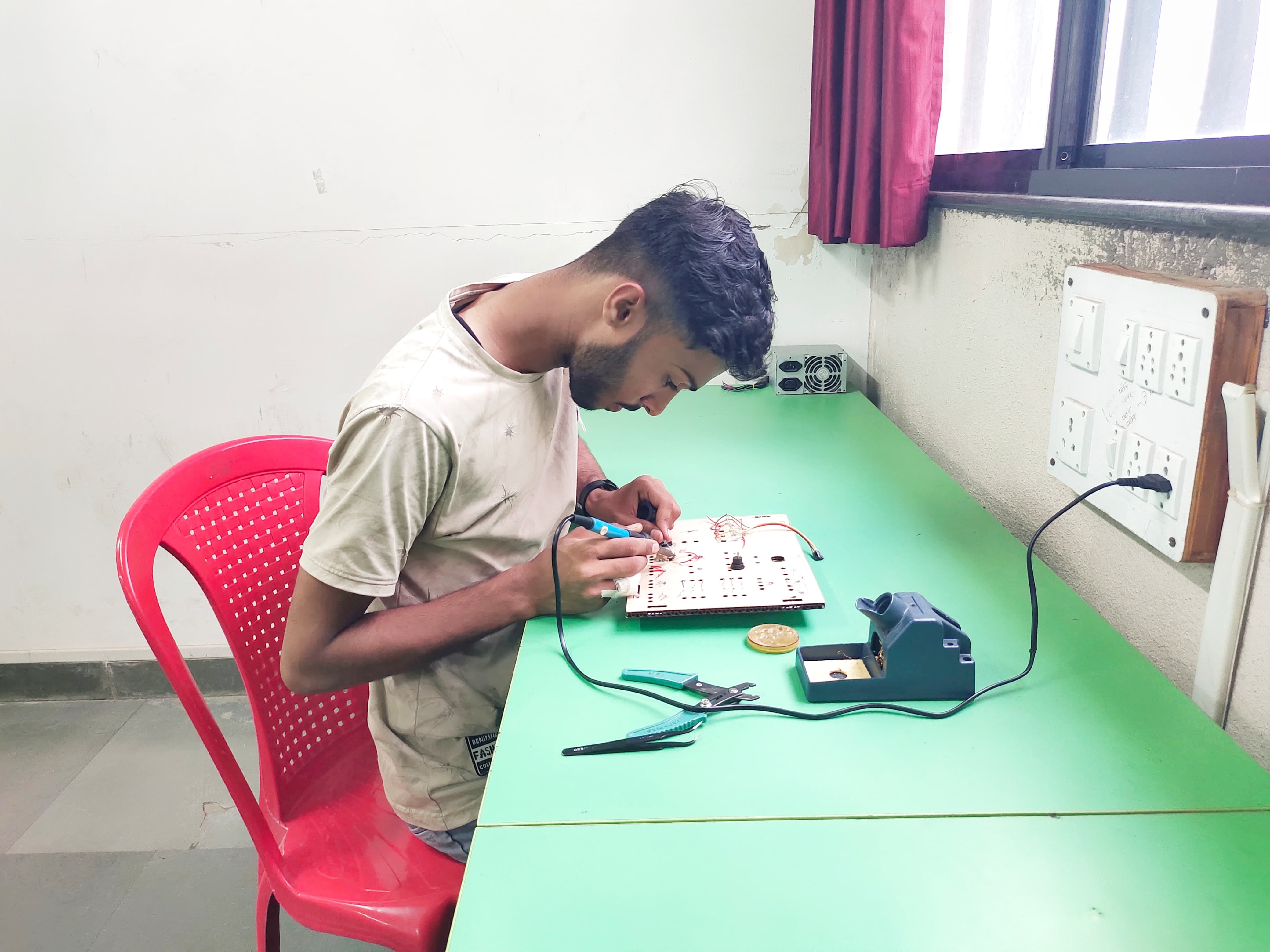
I starded fixing all the components on the board
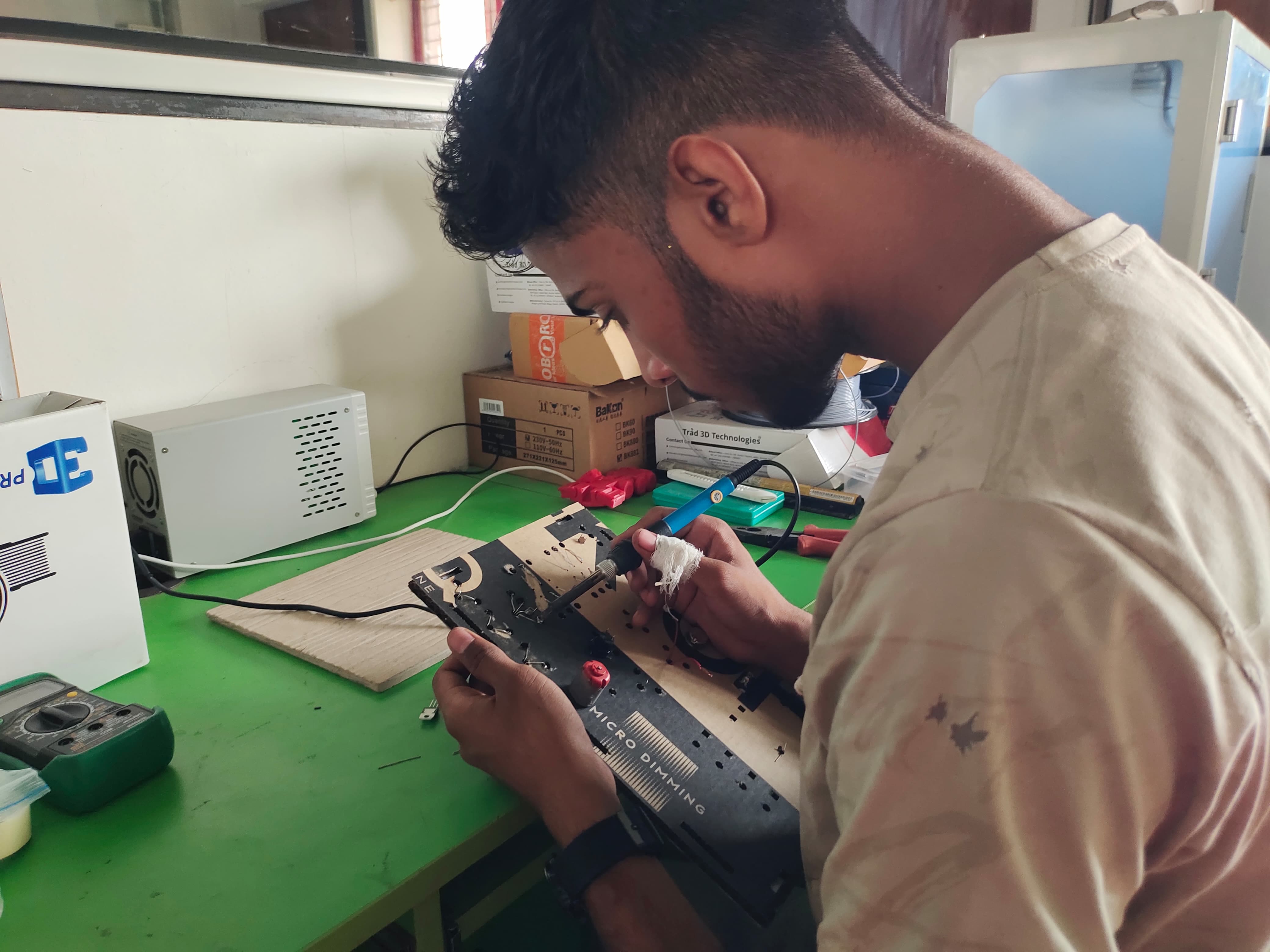
I started soldering the components.
All the components are soldered with the springs by which the students can able to make the connections.
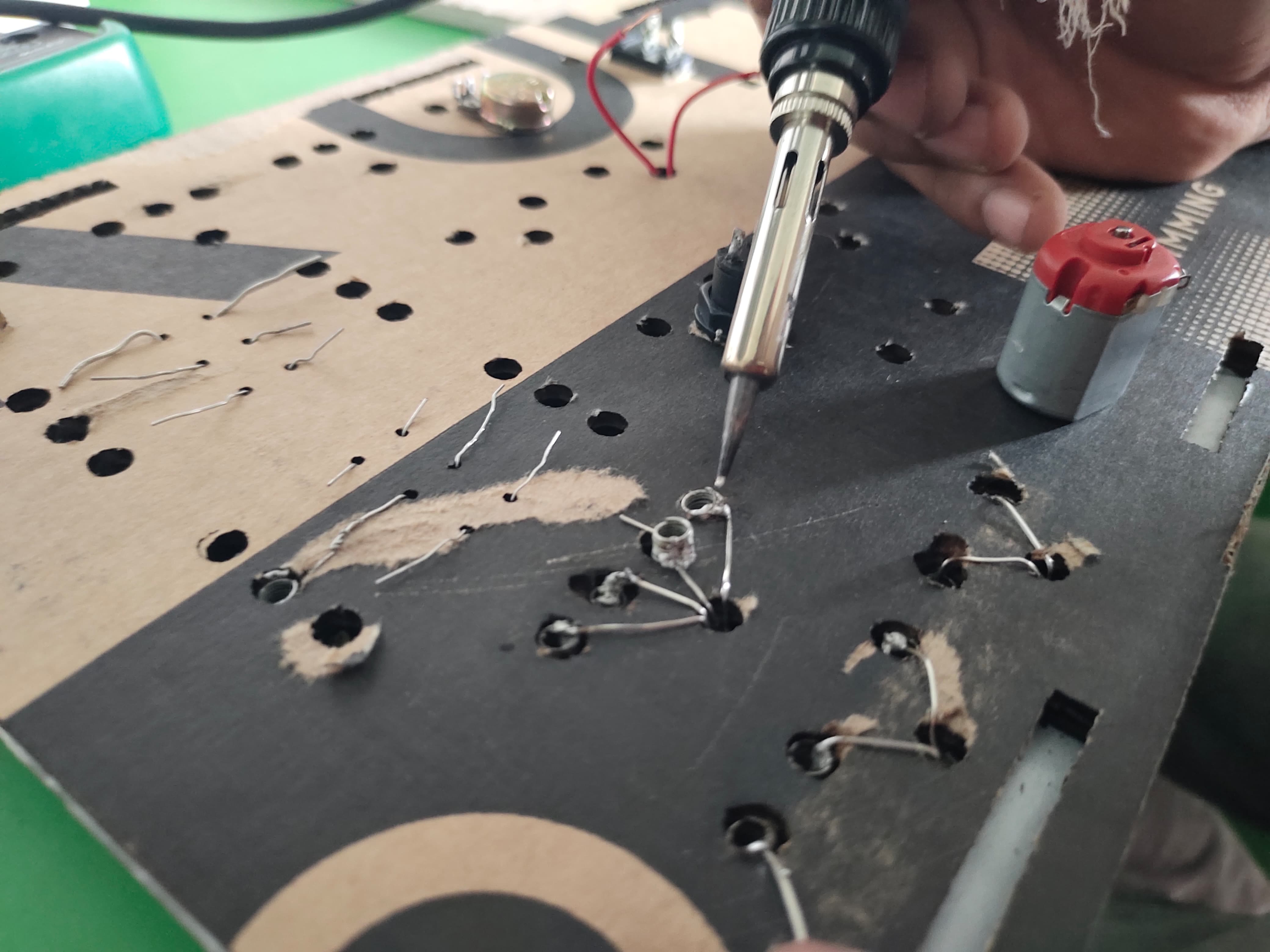
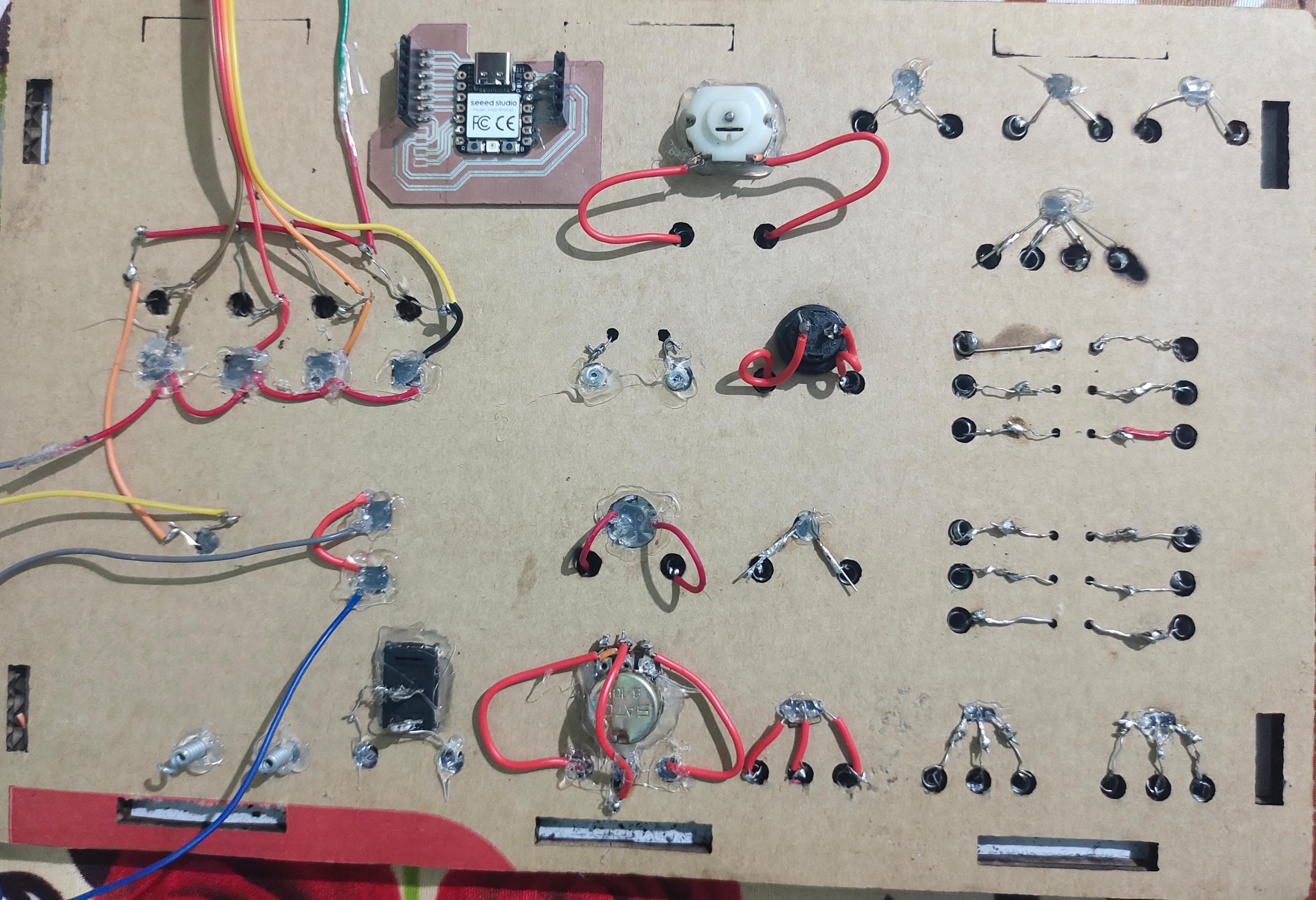
This is the board looks like from inside after soldering
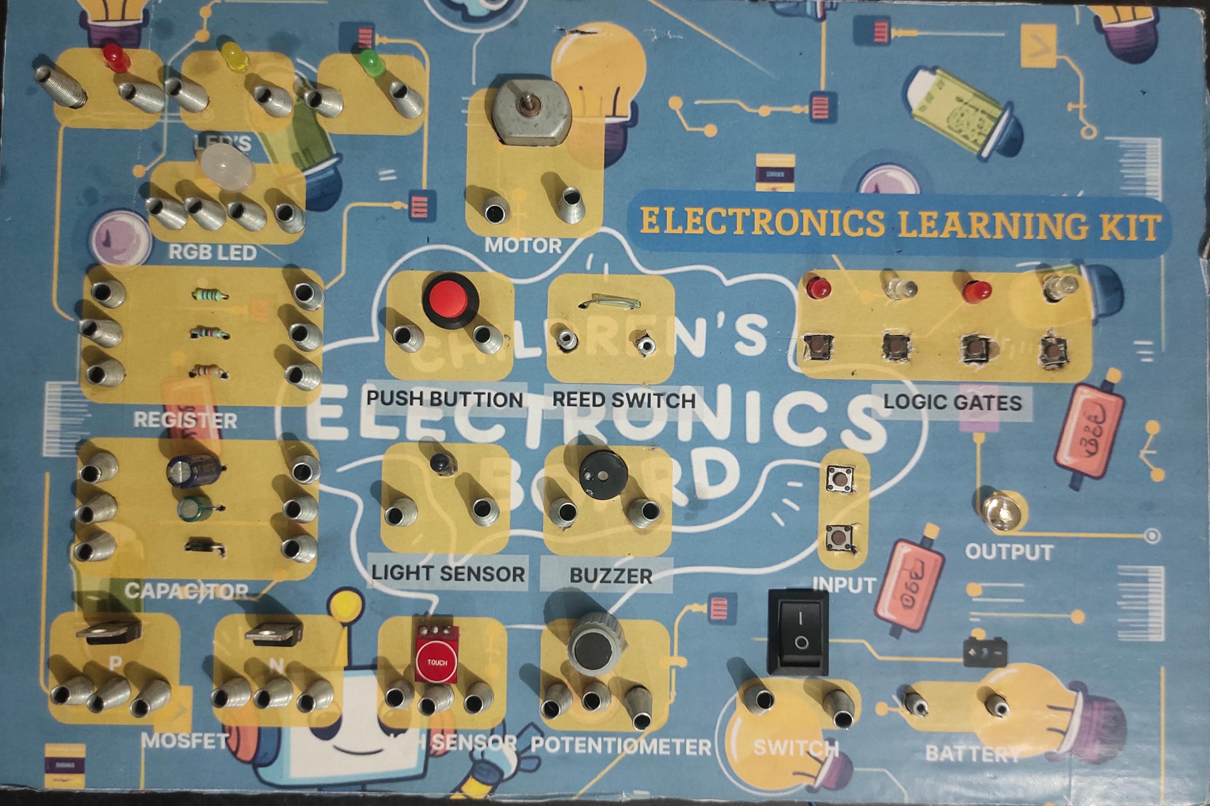
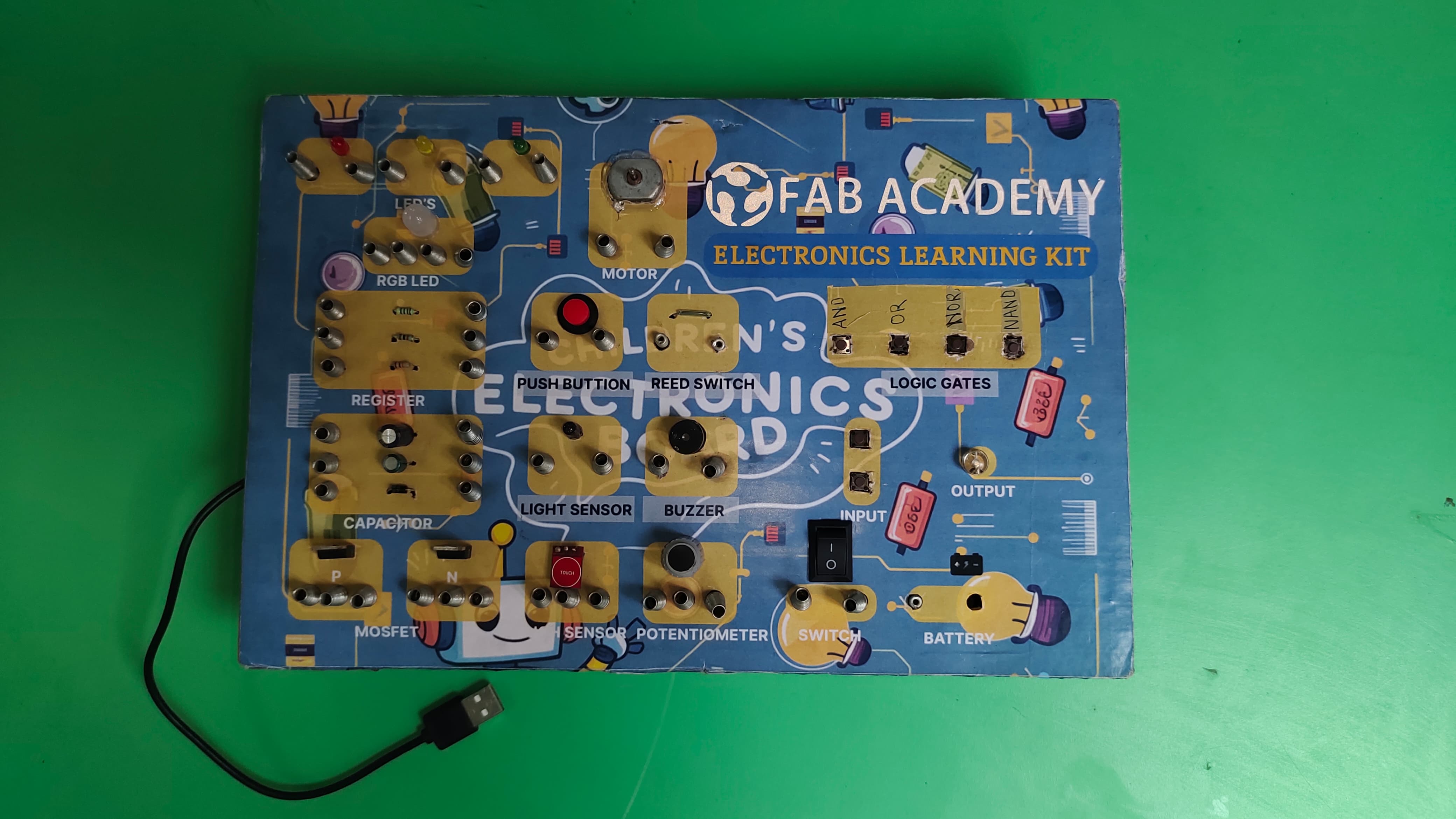
This is the board looks like from outside after placing the components and soldering them.