
Project
Autonomous 4W Rrobotics
Organization of Final Project Work
- Project Discription
- Project understanding
- Materials
- Electronic production
- Interfacing
- CAD
- Backed Interface of Controller
- Developemnt
- Final result
- File to download
- License Agreement
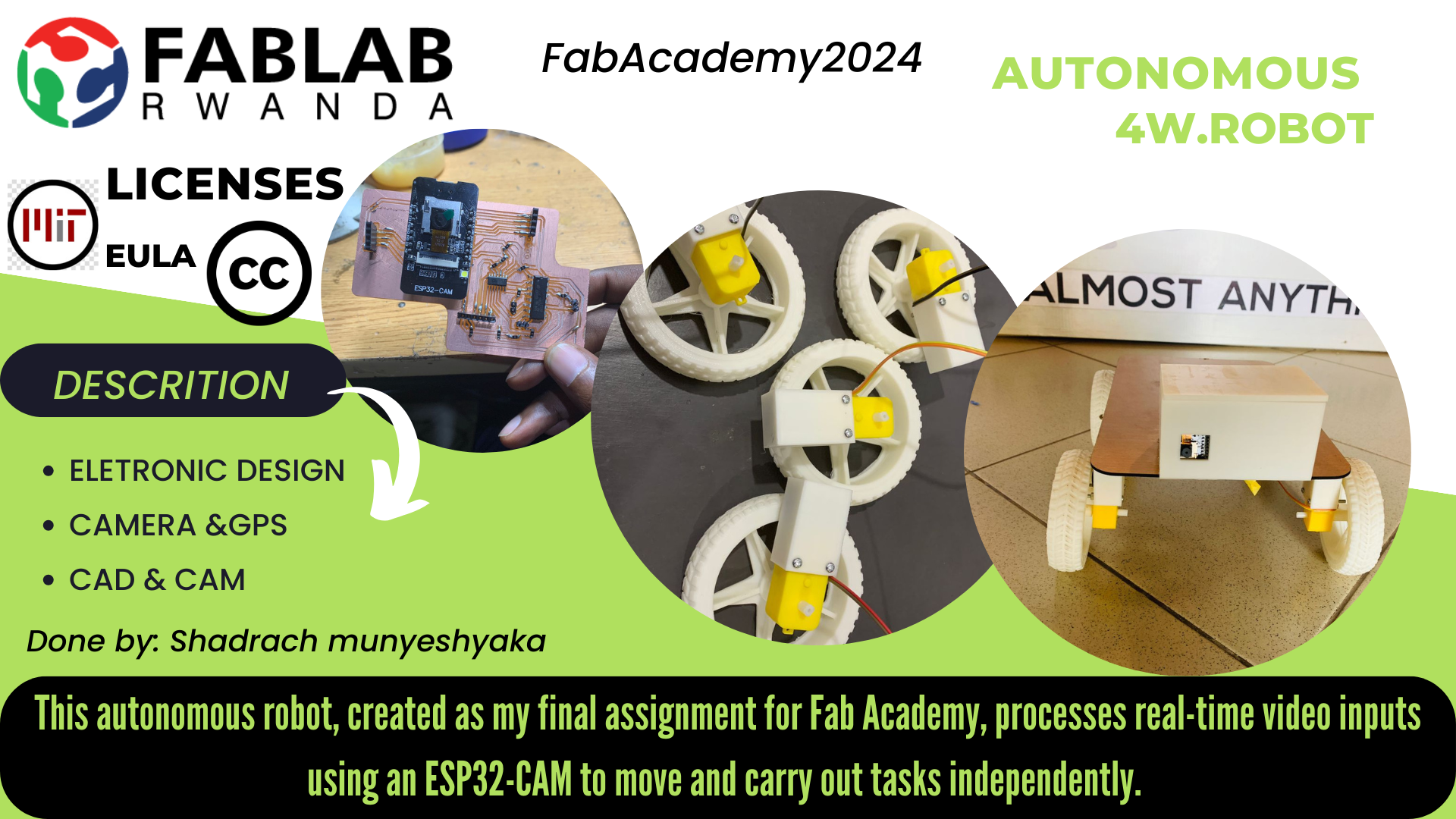
Project Name: Autonomous 4W Rrobotics
My presentation and Video
Slide presentation
Video Clip
Output Video
Description
Overview
The Autonomous 4W Robotics project is an innovative venture aimed at developing a four-wheeled robot equipped with advanced video capturing and real-time remote control capabilities. This project integrates cutting-edge technology to enable users to remotely navigate and control the robot via a web browser, making it a versatile tool for various applications such as surveillance, exploration, and remote assistance.
Features:
- Video Capture:
- The robot is designed with high-resolution cameras to capture clear and detailed video footage.
- The captured video is streamed live over the internet, providing real-time visual feedback to the user.
- Remote Control:
- Users can control the robot remotely through an intuitive web-based interface.
- The robot's movement can be navigated in real-time using standard web browsers, eliminating the need for specialized software.
- Real-Time Streaming:
- The video feed is transmitted over IP, allowing users to view the live stream from any location with internet access.
- The streaming is optimized for low latency to ensure immediate response to user commands.
- Autonomous Navigation:
- The robot can be programmed to navigate autonomously in predefined environments, avoiding obstacles and adjusting its path as needed.
- Users can also switch between manual and autonomous modes seamlessly.
Applications:
- Surveillance:
- Ideal for monitoring sensitive areas remotely, providing a mobile surveillance solution.
- Exploration:
- Suitable for exploring hard-to-reach or hazardous environments, such as industrial sites, disaster areas, or remote landscapes.
- Remote Assistance:
- Can be used in scenarios where remote inspection or assistance is required, such as in healthcare, maintenance, or security.
Technical Specifications:
- Chassis:Robust four-wheel drive for stability and maneuverability.
- Camera:High-definition camera with adjustable angles for comprehensive video capture.
- Connectivity:Wi-Fi enabled for seamless internet connection and remote control.
- Control Interface:Web-based interface accessible from any device with a browser.
- Power Supply:Rechargeable batteries ensuring extended operation time.
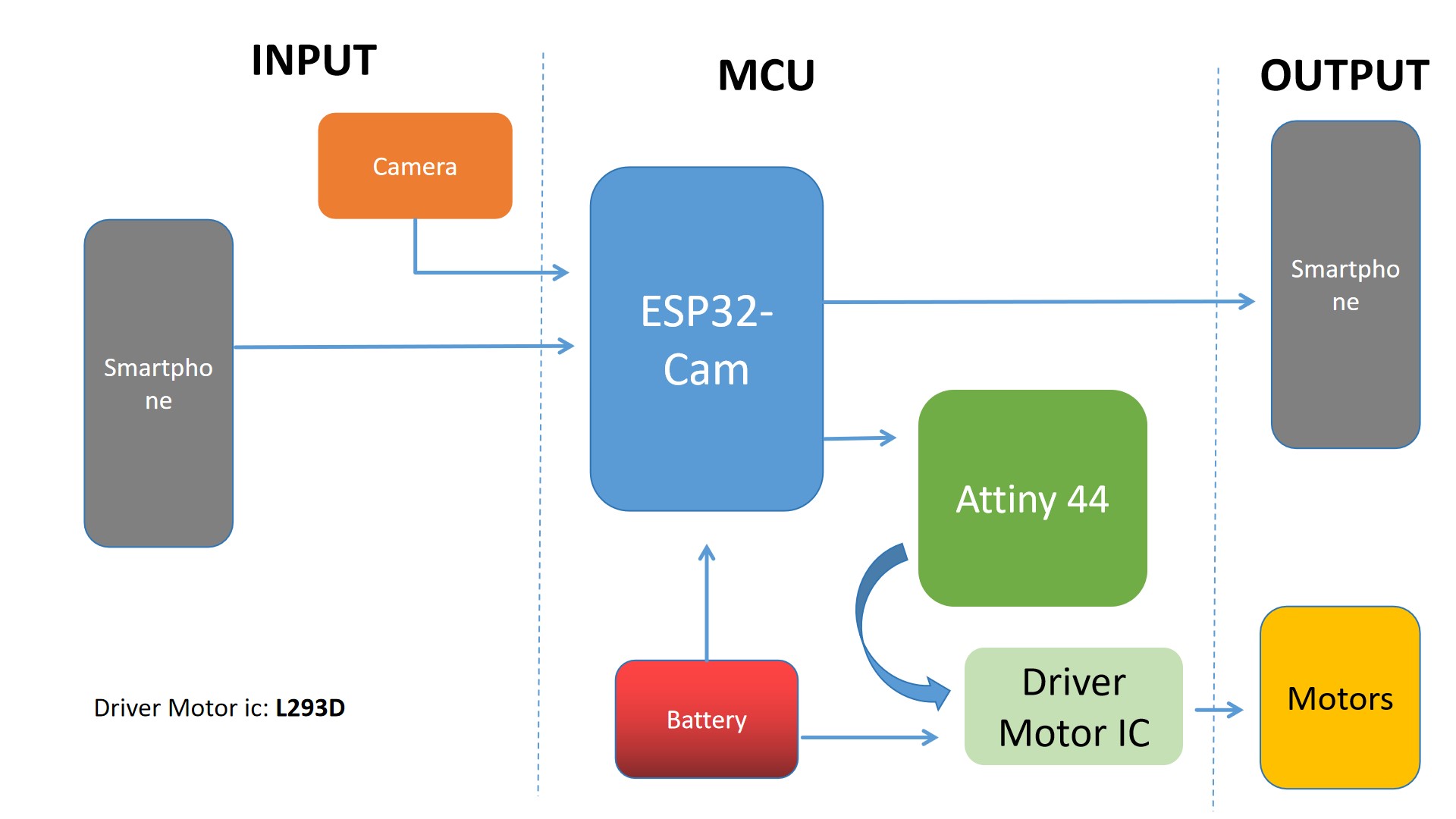
System Block Diagram
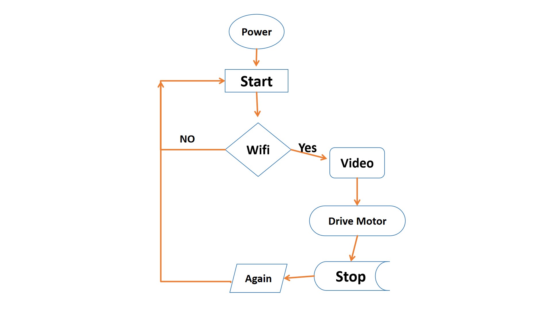
Flow Chart of the system
Project understanding
During the implementation of my project for Fab Academy, I began by sketching out the design and functionality of my robot on paper. I created two detailed drawings: one illustrating the appearance and structure of the robot, and another depicting the user interface. These sketches served as essential blueprints, guiding the development process and ensuring a clear vision for both the hardware and software aspects of the project.
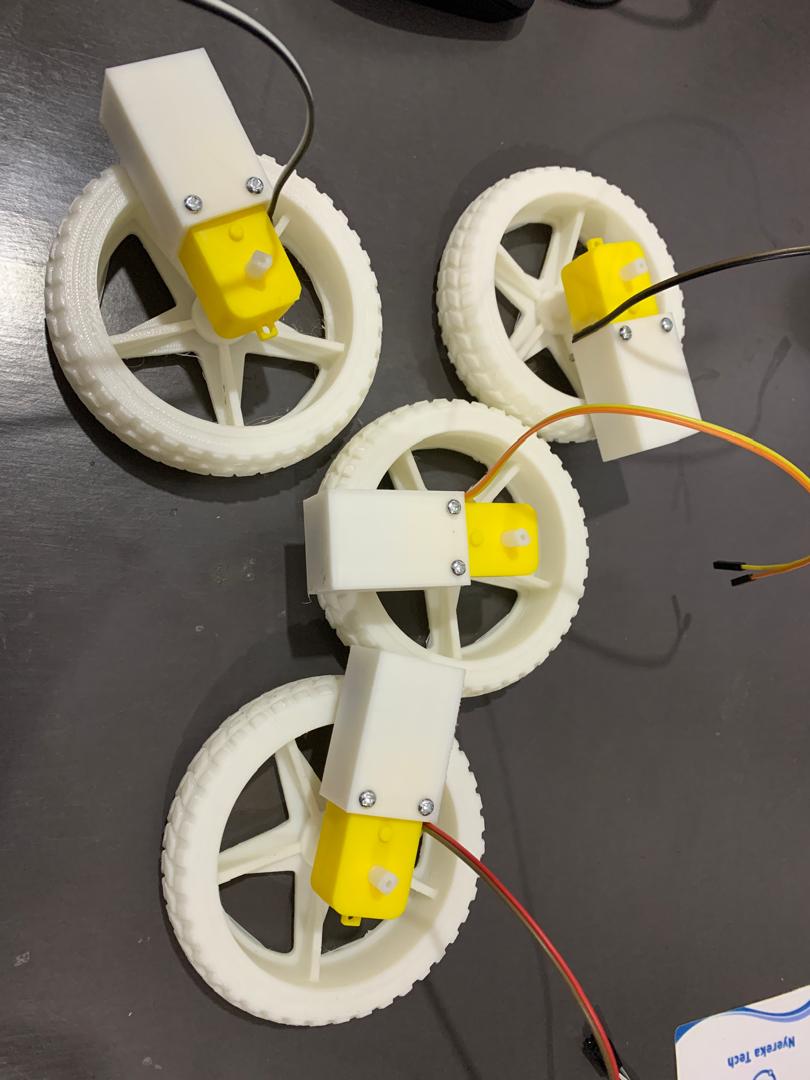
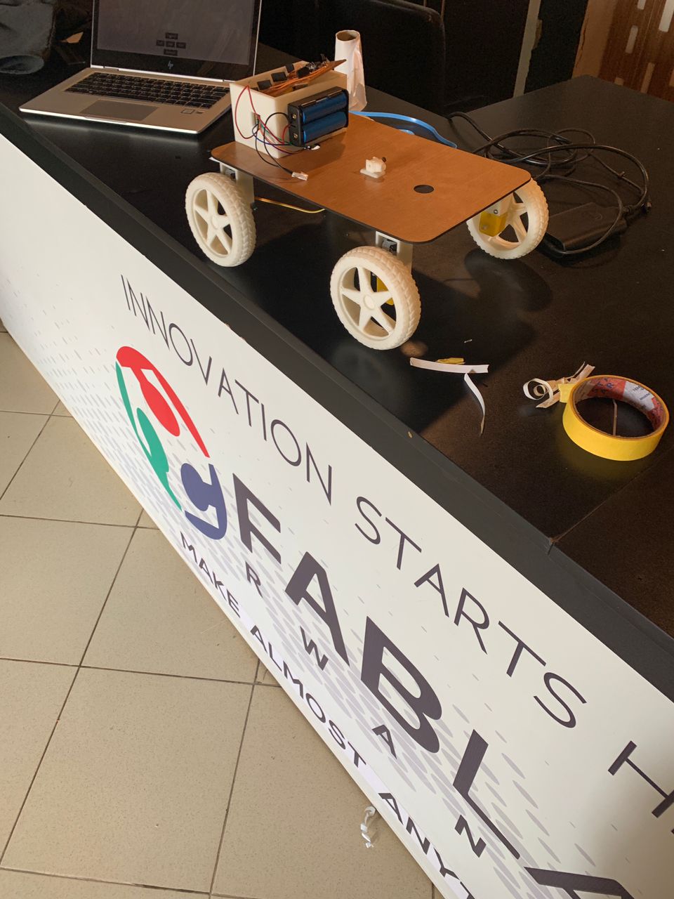
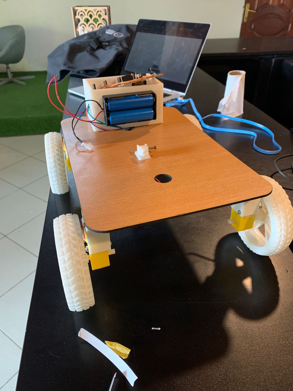
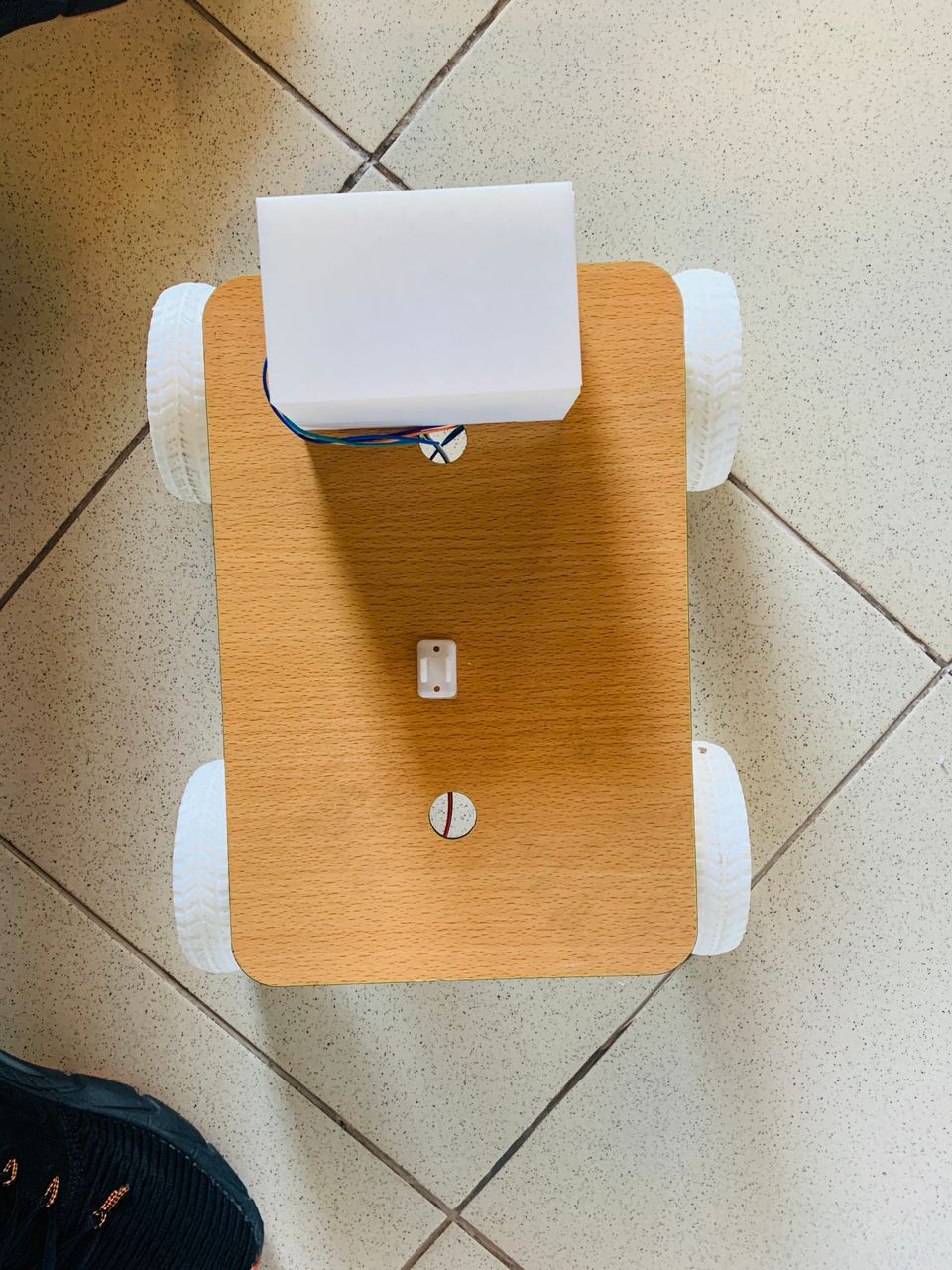
Developing robotics for Fab Academy requires meticulous attention to detail, particularly in the precise connection of wheels and motors. This precision is essential to create a robust and reliable robot capable of navigating high-risk zones with ease. Ensuring these components are accurately connected will enhance the robot's performance and safety in challenging environments.
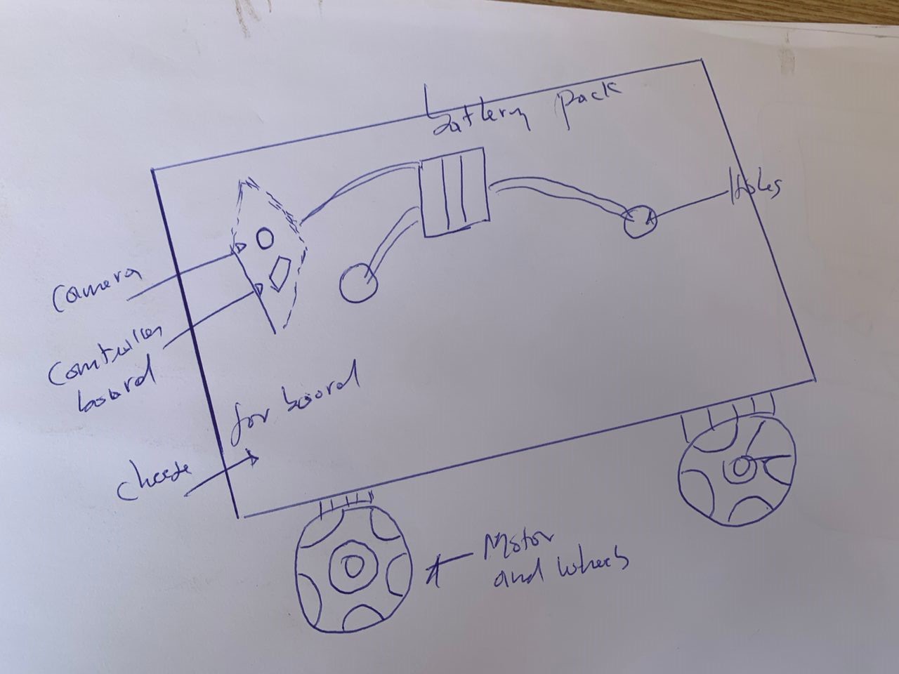
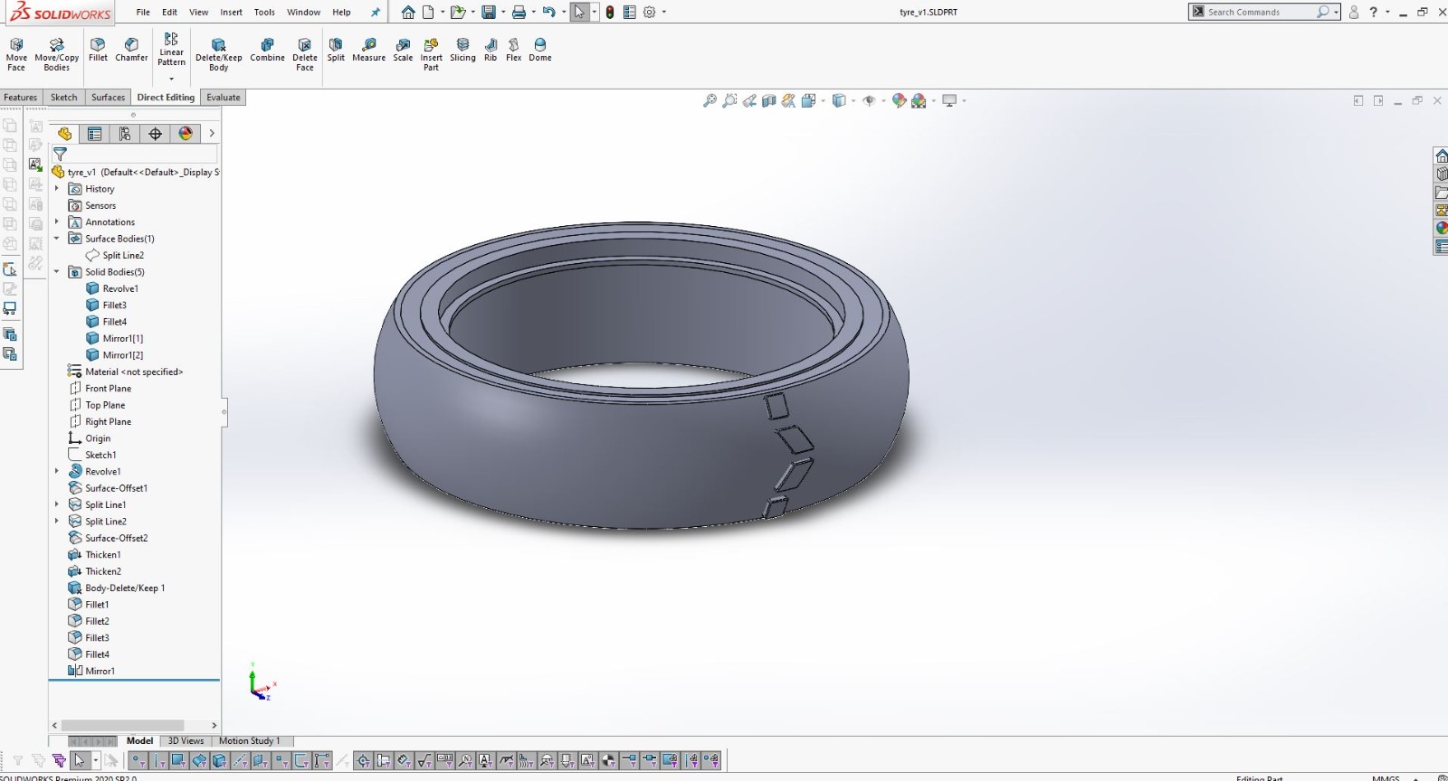
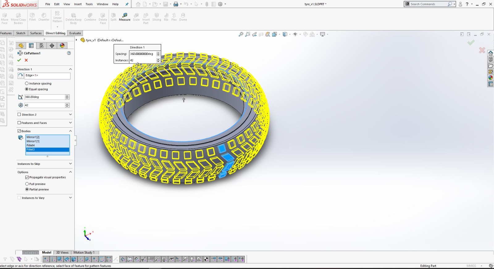
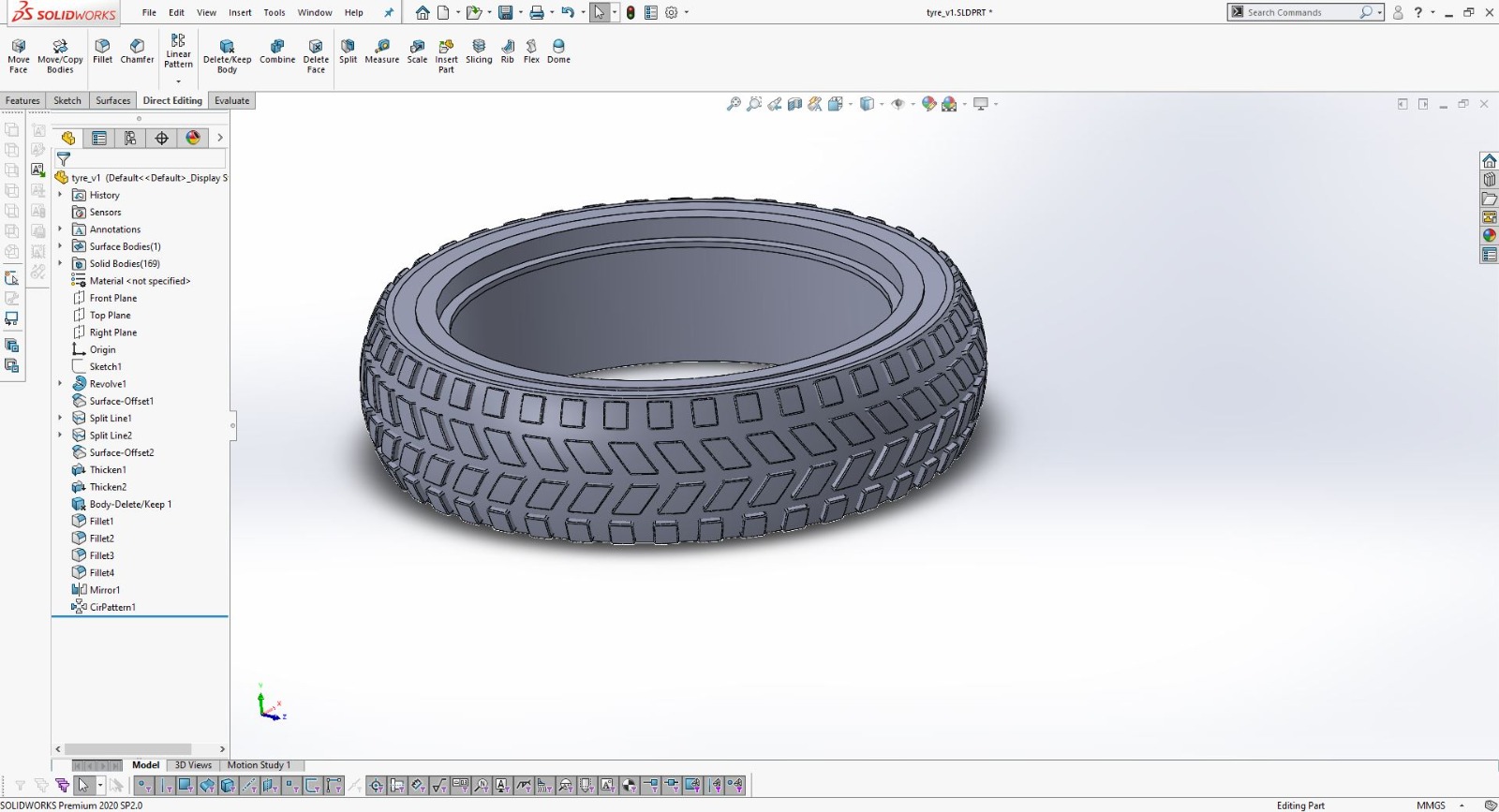
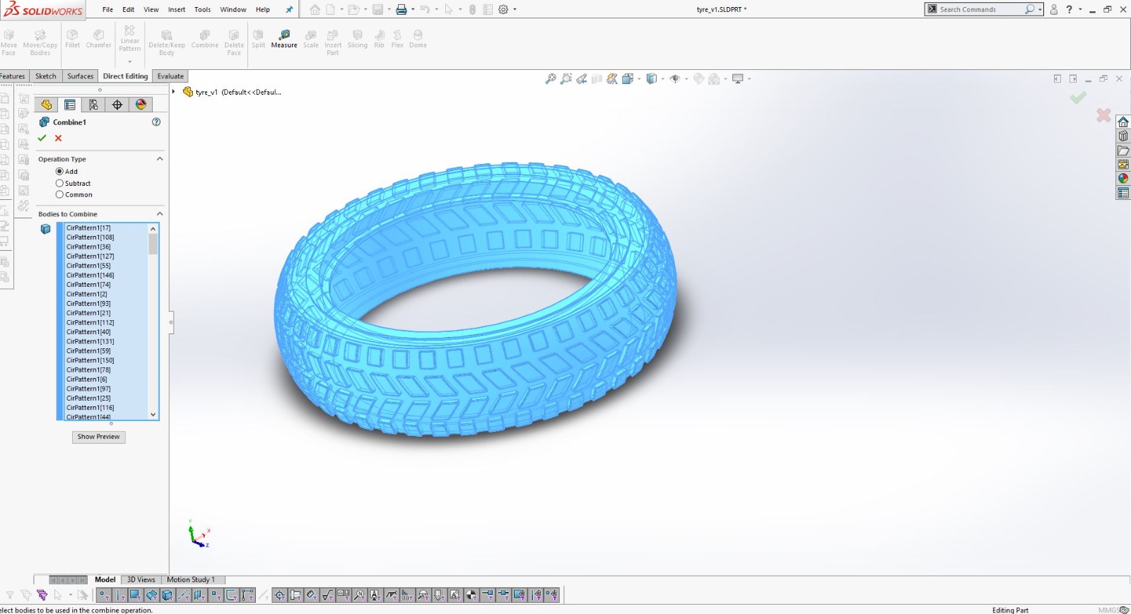
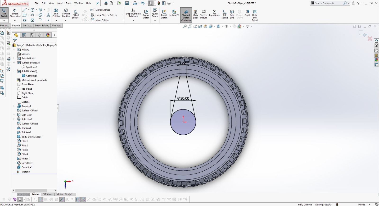
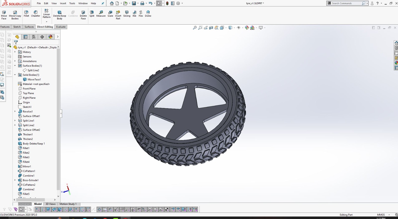
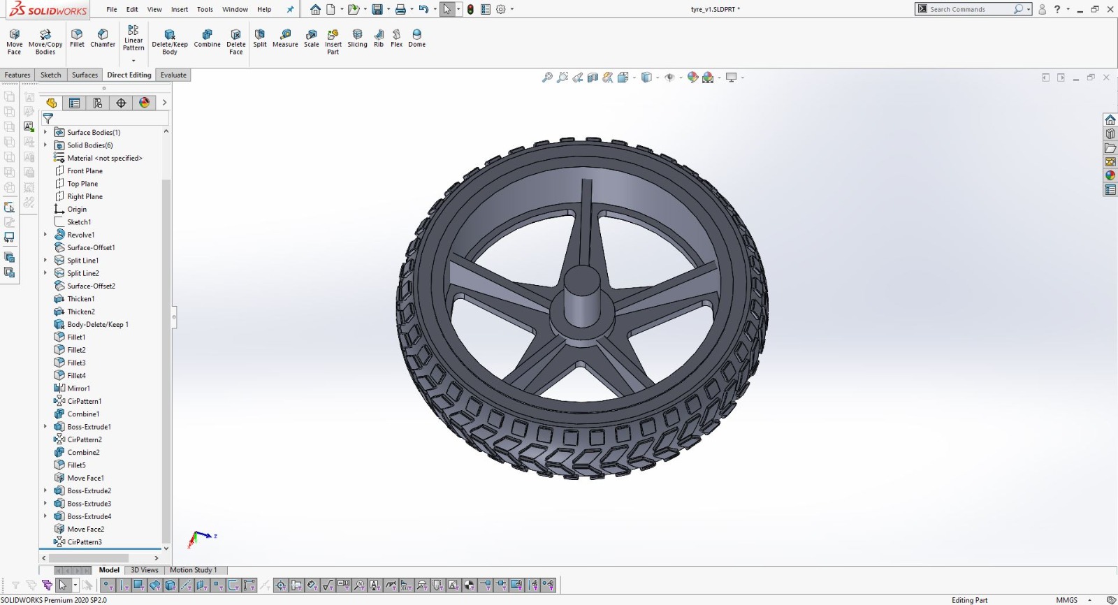
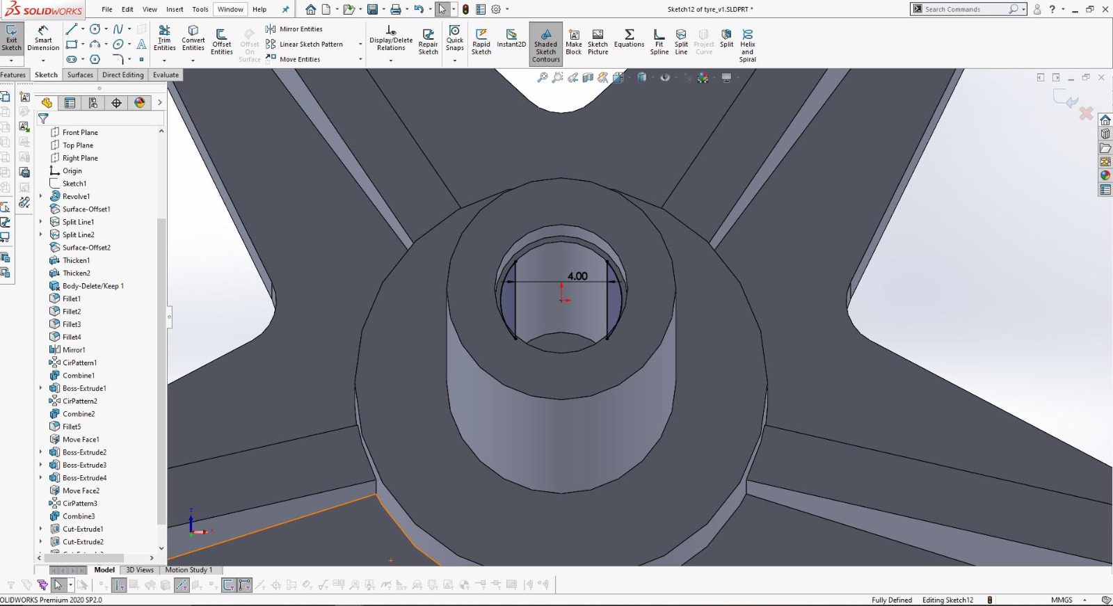
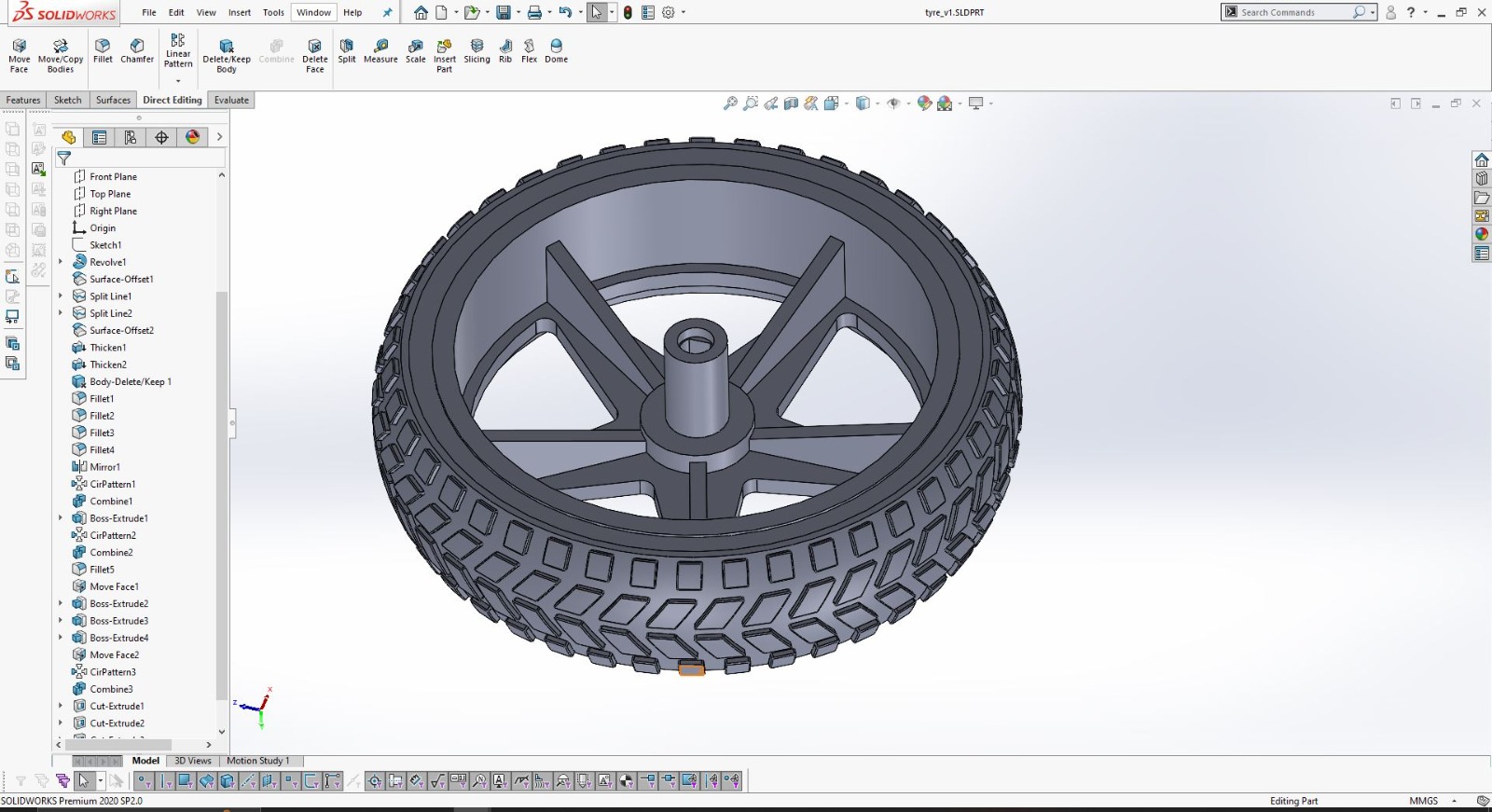
As seen in the image above, my goal is to design unique and innovative robotic wheels that stand out from the standard options available on the market. These wheels are intended to be larger and more aesthetically pleasing. I aim to apply the electronic design principles and other skills I have acquired from Fab Academy to bring this concept to life. This sketch represents my vision for the final appearance of the robot.
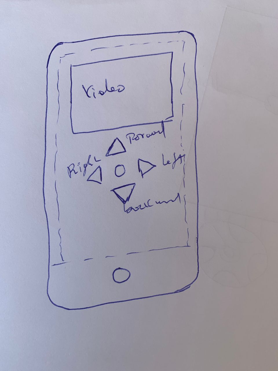
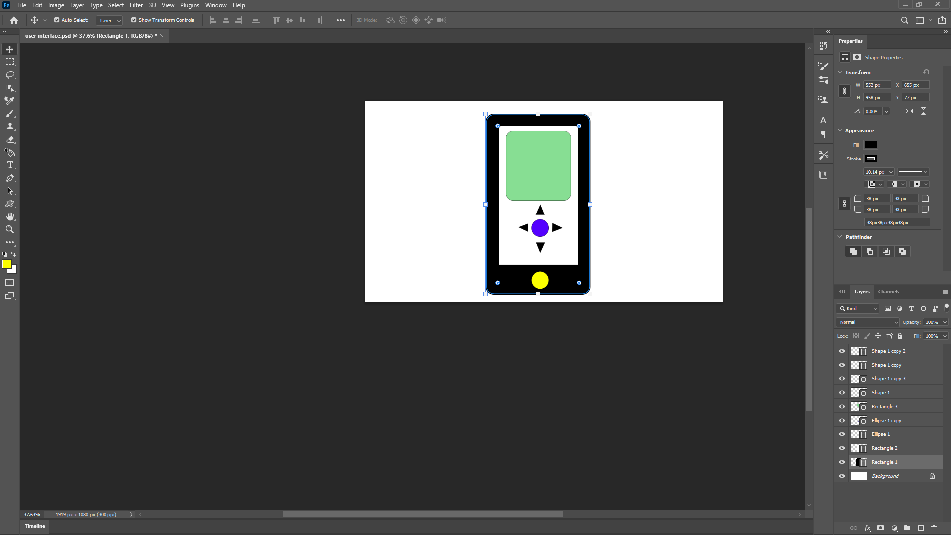
I designed a user interface that allows seamless control of the robot, as shown in the accompanying image. Given the widespread use and convenience of smartphones, I opted to develop a smartphone user interface. This intuitive and user-friendly interface makes it easy for anyone to control the robot using a device they already have.
With this interface, users can efficiently operate the robot for various purposes, such as security monitoring or other applications. This design leverages the skills and knowledge I gained from the Fab Academy courses, integrating electronic design and user experience principles to create a practical and accessible control system.
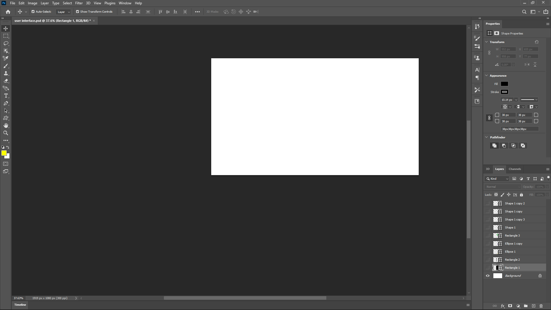
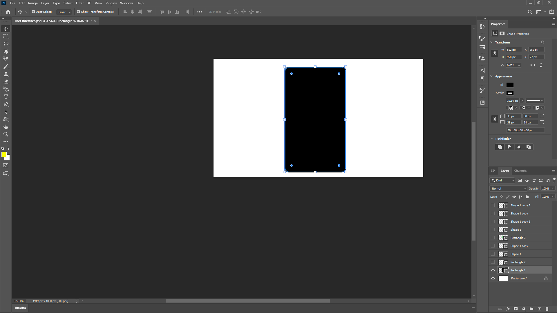
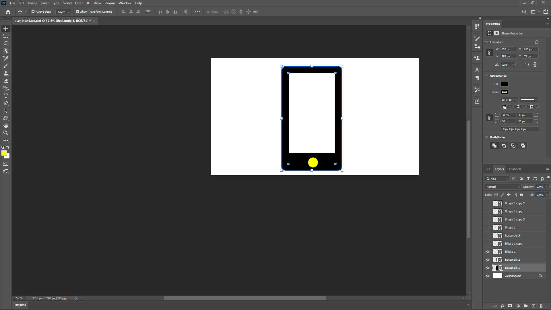
User inter in photoshop
Identify the materials
To begin implementing my project after forming a clear vision of its final appearance, I needed to identify the materials required and the skills I would apply during the prototyping and development stages. Initially, I determined that I needed a camera module to capture video and transmit it to a temporary local server. Additionally, I needed a microcontroller capable of establishing a network with my smartphone to facilitate video streaming. Here are the key components and materials I used:
- ESP32-CAM Boards: For video capture and wireless communication.
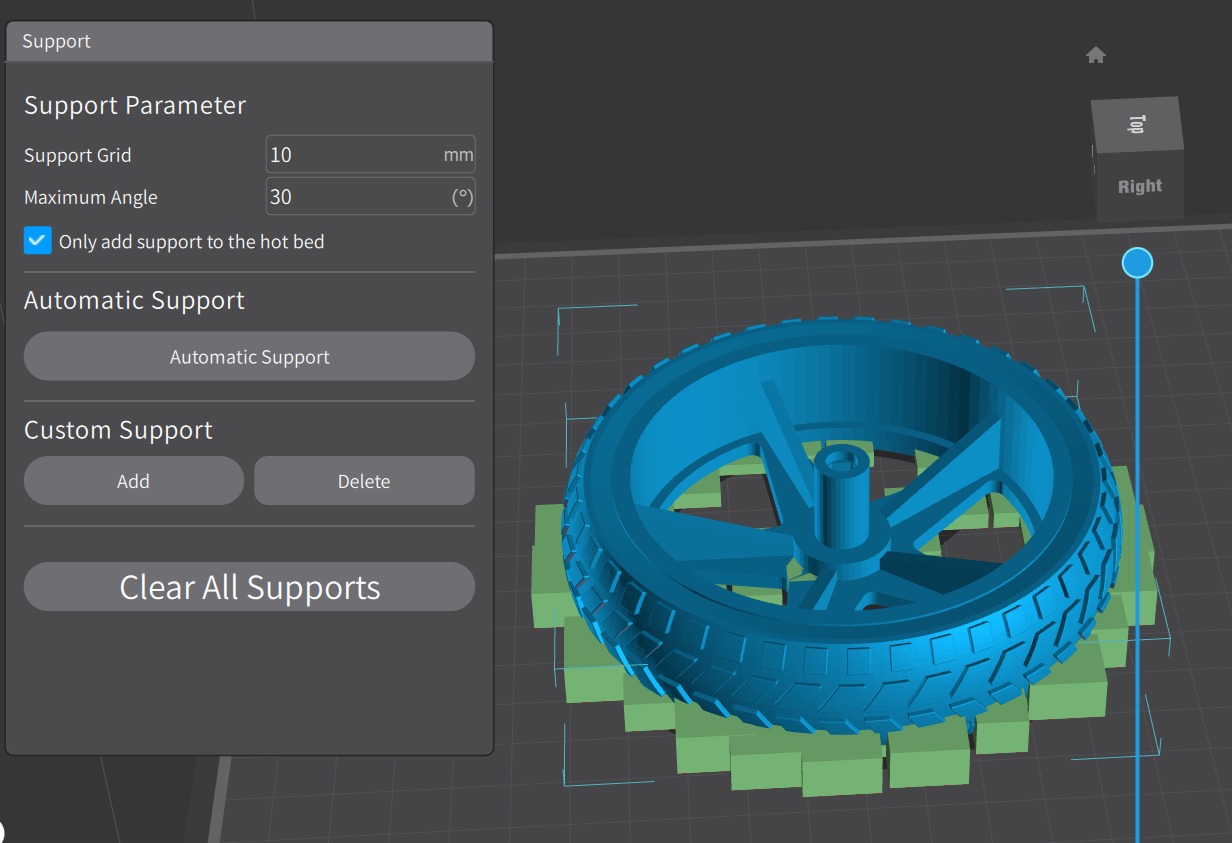
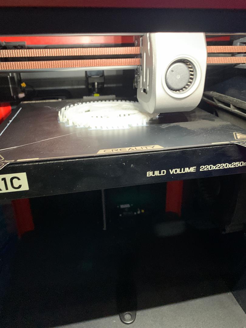
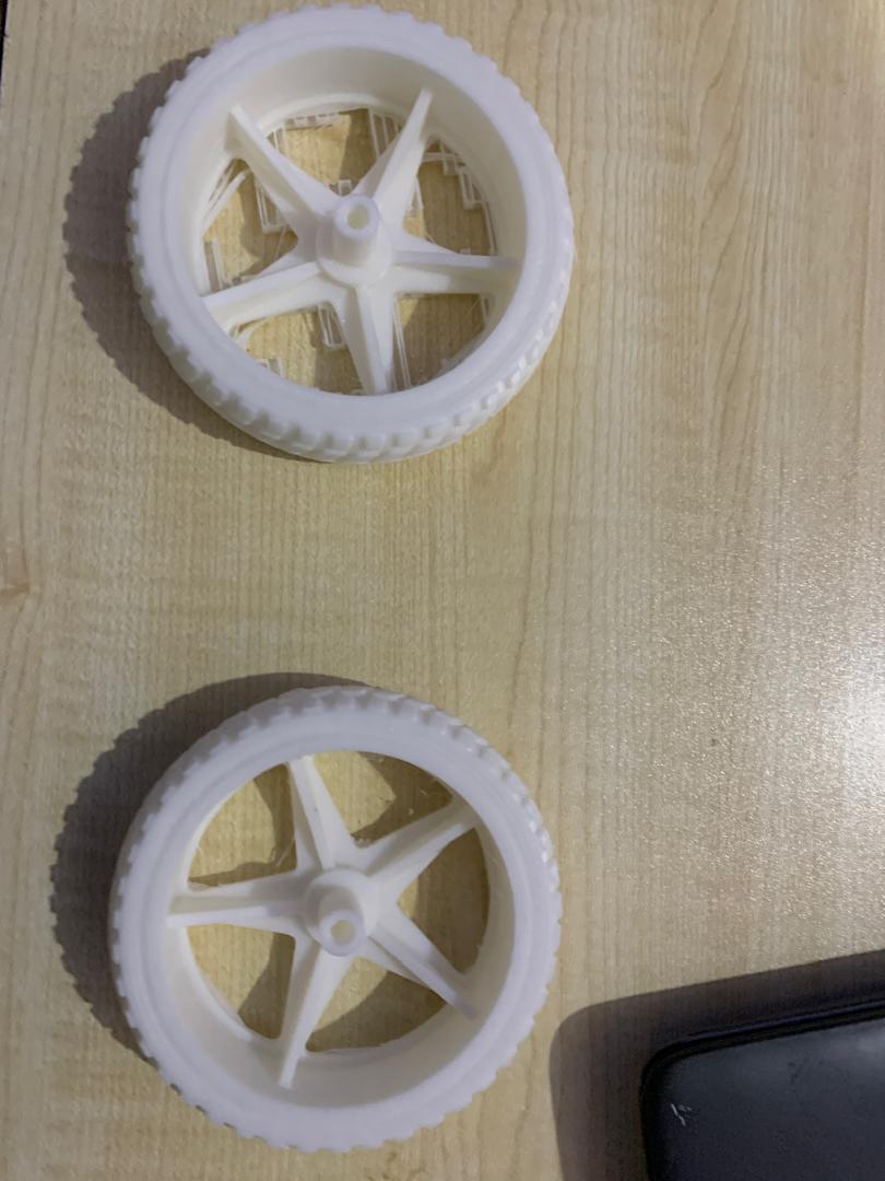
- Filament for Wheels: To 3D print durable and functional wheels.
- Camera for ESP32: To capture high-quality video footage.
- 3.7V Batteries and Battery Pack: To power the robot and its components.
- Jumper Wires: For establishing electrical connections.
- Wood for Laser Cutting: To create the chassis and other structural elements.
- DC Motors: To drive the wheels and enable movement.
- PCB: For integrating and organizing electronic components, designed using EASYEDA.
These components, combined with the skills acquired from Fab Academy courses—such as electronic design, 3D printing, and laser cutting—enabled me to bring my robotic project to life. The hands-on experience and technical knowledge gained from the academy were crucial in developing a functional and efficient robot, capable of being controlled via a smartphone interface for various applications, including security monitoring.
Project Components and Materials
| Component/Material | Description | Image | Shop | Cost in USD |
|---|---|---|---|---|
| ESP32-CAM Boards | For video capture and wireless communication |  |
Nyereka Tech | 14.4$ |
| Filament for Wheels | To 3D print durable and functional wheels | 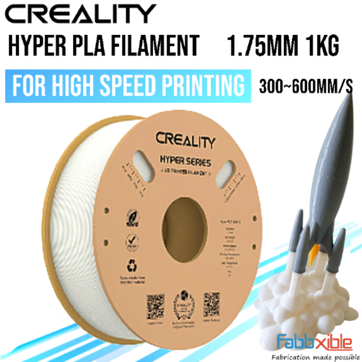 |
Nyereka Tech | 43.1$ |
| Camera for ESP32 | To capture high-quality video footage | 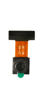 |
Nyereka Tech | 5.3$ |
| 3.7V Batteries and Battery Pack | To power the robot and its components | 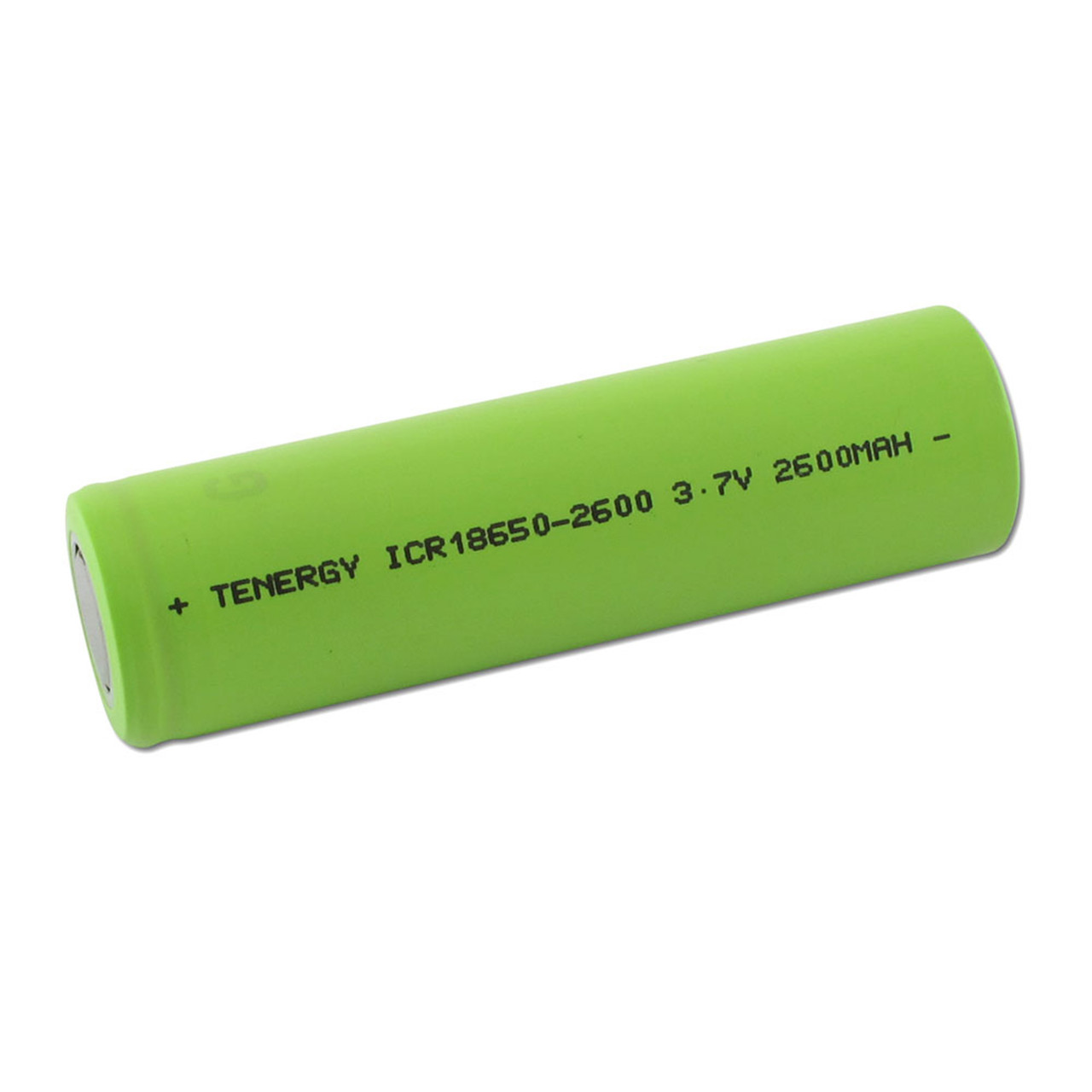 |
Nyereka Tech | 4.2$ |
| Jumper Wires | For establishing electrical connections | 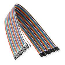 |
Nyereka Tech | 1.3$ |
| Wood for Laser Cutting | To create the chassis and other structural elements | I got this from Fablab Rwanda | From FabLab Rwanda | FabLab |
| DC Motors | To drive the wheels and enable movement | 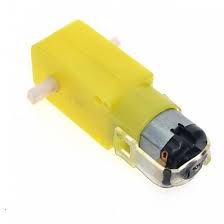 |
Nyereka Tech | 2.1$ |
| PCB | For integrating and organizing electronic components, designed using EASYEDA | 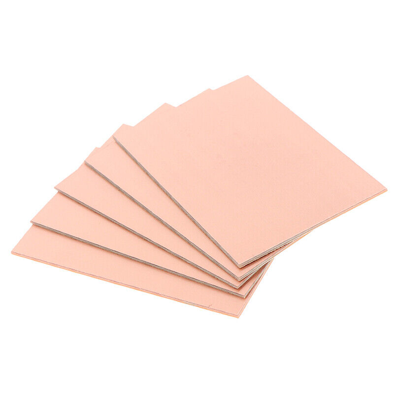 |
Nyereka Tech | 3$ |
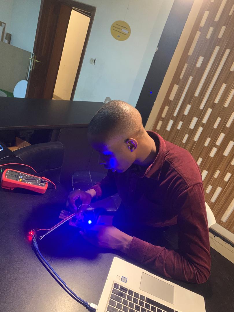
Electronic production
To effectively design circuits in EasyEDA, I first needed to understand the working principles of my electronic components, including their pinouts and configuration. This foundational knowledge was crucial for accurately designing and implementing my project. Below are the detailed technical specifications of the materials and components used:
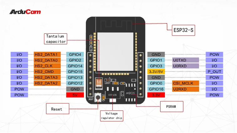
- ESP32-CAM Boards
- A microcontroller with integrated Wi-Fi and Bluetooth, equipped with a camera module.
- Specifications:
- Processor: Xtensa® 32-bit LX6 dual-core
- Flash Memory: 4MB
- Camera: OV2640, 2MP
- Connectivity: 802.11b/g/n Wi-Fi, Bluetooth v4.2 BR/EDR and BLE
- GPIO: 9
- Power Supply: 5V via Micro USB
- Pinout confuguration
- Filament for Wheels
- 3D printing material used to create durable wheels.
- Specifications:
- Material: PLA (Polylactic Acid)
- Diameter: 1.75mm
- Recommended Printing Temperature: 190-220°C
- Filament Weight: 1kg
- Specifications
- Camera for ESP32
- A high-definition camera module compatible with ESP32.
- Specifications:
- Sensor: OV2640
- Resolution: 2MP
- Lens: 1/4 inch
- Viewing Angle: 65°
- Maximum Frame Rate: 15 FPS (UXGA), 60 FPS (CIF)
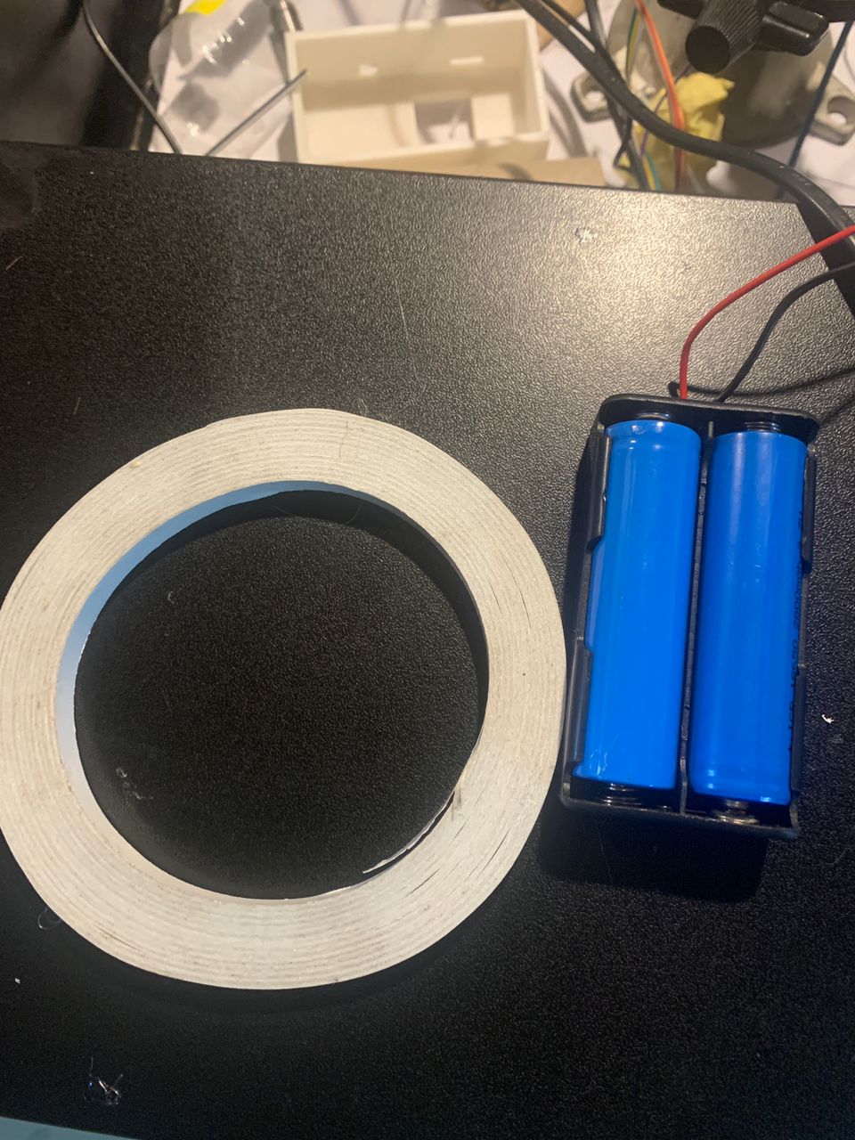
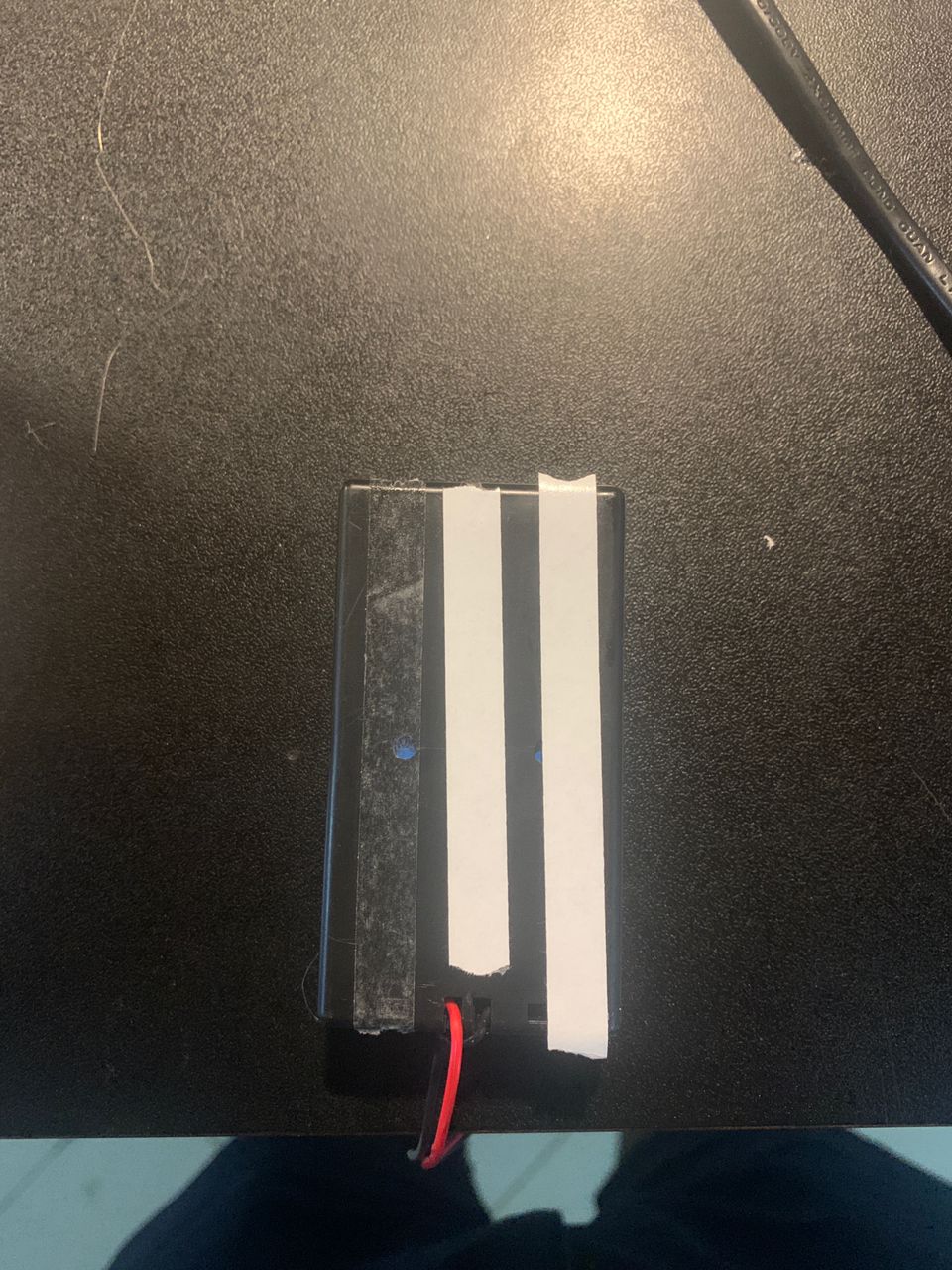
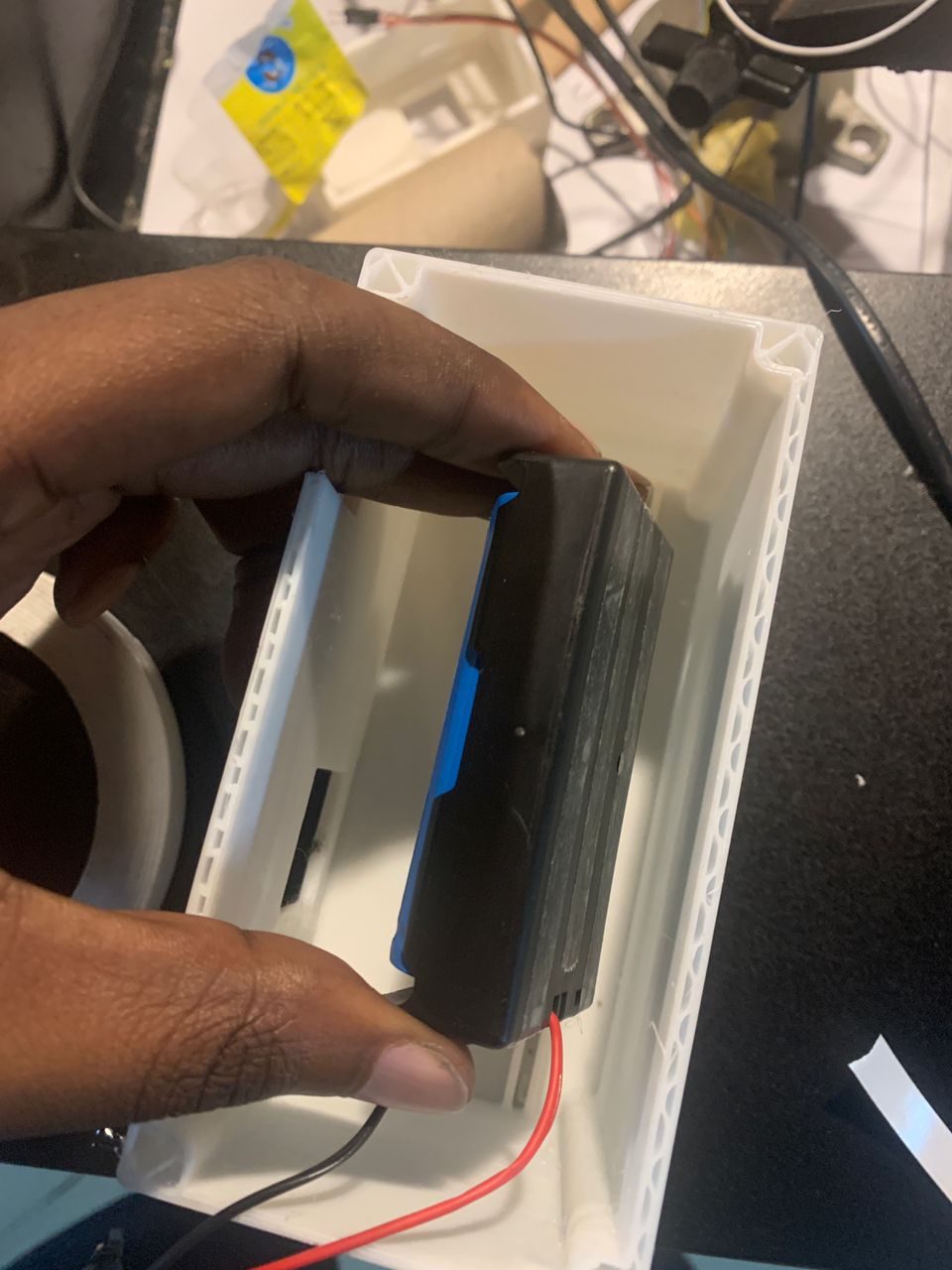
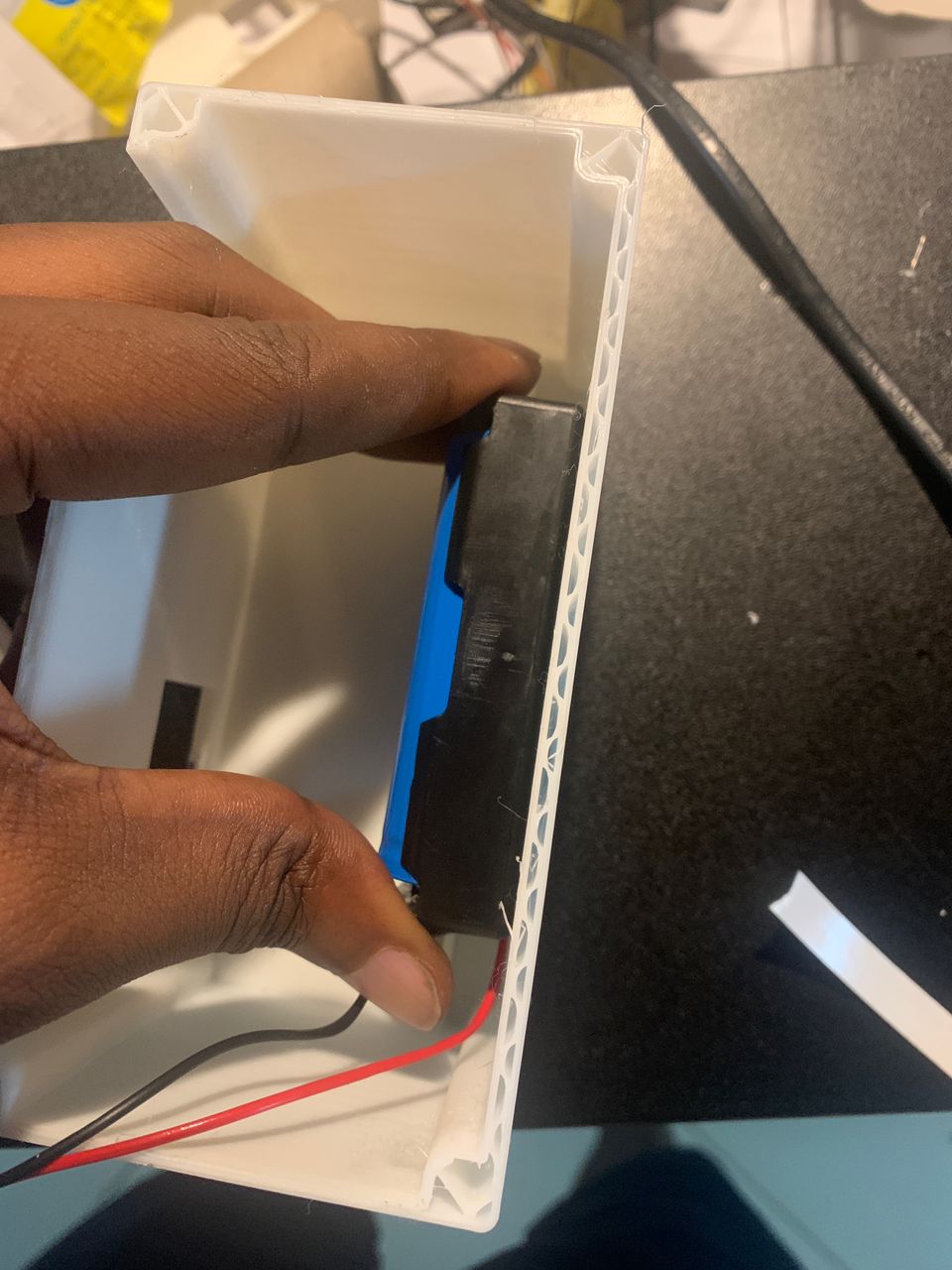
- 3.7V Batteries and Battery Pack
- Rechargeable batteries and pack to power the robot.
- Specifications:
- Voltage: 3.7V
- Capacity: 2000mAh
- Chemistry: Lithium-ion
- Battery Pack: Holds 3 batteries, with built-in protection circuit
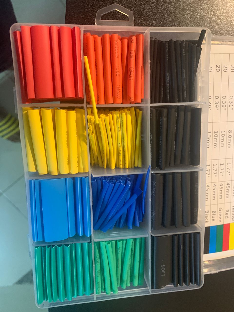
- Jumper Wires
- Wires used for making electrical connections between components.
- Specifications:
- Length: 10cm, 20cm, 30cm
- Type: Male to Male, Male to Female, Female to Female
- Insulation Material: PVC
- Conductor Material: Copper
- Wood for Laser Cutting
- Material for creating the chassis and structural components of the robot.
- Specifications:
- Type: Plywood
- Thickness: 3mm, 5mm
- Sheet Size: 600mm x 400mm
- Suitable for: Laser cutting and engraving
- DC Motors
- Motors used to drive the robot's wheels.
- Specifications:
- Voltage: 6V
- No-Load Speed: 200 RPM
- Stall Torque: 1.2 kg.cm
- Shaft Diameter: 5mm
- Current: 200mA (no load), 1.2A (stall)
- Laminated PCB
- Printed circuit board for integrating and organizing electronic components, designed using EasyEDA.
- Specifications:
- Layers: 2
- Material: FR4
- Thickness: 1.6mm
- Copper Thickness: 1oz (35µm)
- Surface Finish: HASL (Hot Air Solder Leveling)
- Design Software: EasyEDA
understanding the technical specifications and functionalities of these components, I could accurately design and implement my project using EasyEDA software. The skills and knowledge gained from Fab Academy courses were instrumental in guiding this process, ensuring a precise and efficient approach to developing my robotic system.
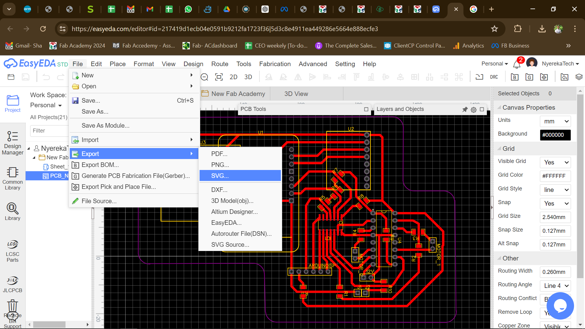
EasyEda circuit
To begin using the EasyEDA application, the first step is to register for an account on their online platform. After completing the registration process, you need to create a new project. I initiated a project and named it "Fab Academy." This allowed me to access all the necessary components and tools within the application.
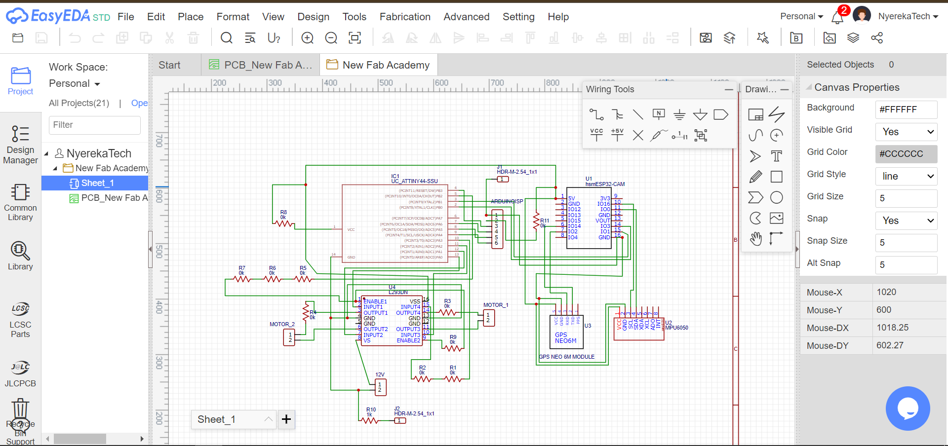
Once the project was set up, I began designing my circuit by connecting all the required materials. This involved selecting and placing components such as resistors, capacitors, microcontrollers, and sensors from the EasyEDA library. Using the schematic capture tool, I meticulously connected each component to create a coherent and functional circuit.
During the design process, I applied various skills learned from the Fab Academy courses, including understanding electronic components, schematic design, and PCB layout techniques. The goal was to ensure that the circuit was not only functional but also optimized for performance and manufacturability.
Below is a screenshot of the final circuit design in EasyEDA. This design includes all the necessary connections and components, reflecting the knowledge and skills gained from the Fab Academy courses. It represents a significant step towards the successful implementation of my project, demonstrating the practical application of theoretical knowledge acquired during the course.
By leveraging the EasyEDA application, I was able to streamline the circuit design process, ensuring accuracy and efficiency. This tool, combined with the foundational knowledge from the Fab Academy, enabled me to create a robust and reliable electronic design ready for further development and testing.
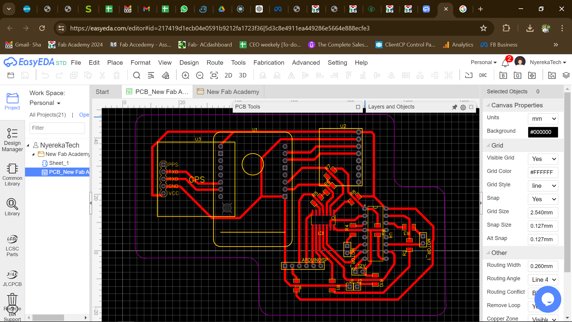
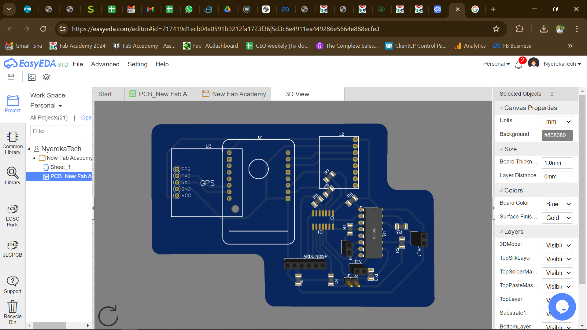
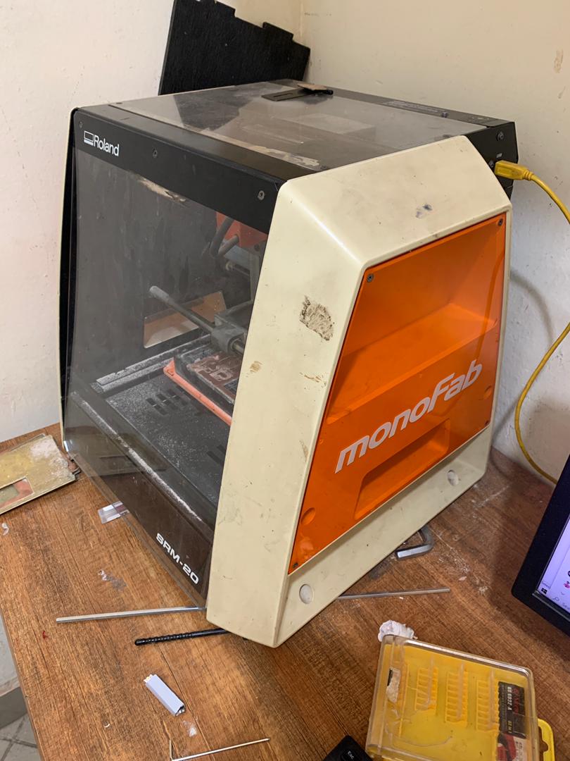
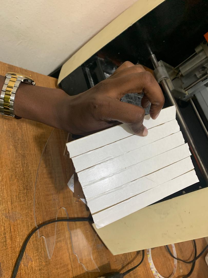
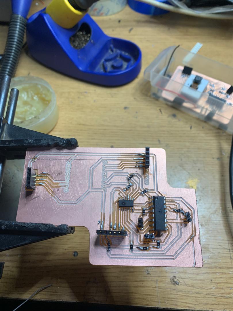
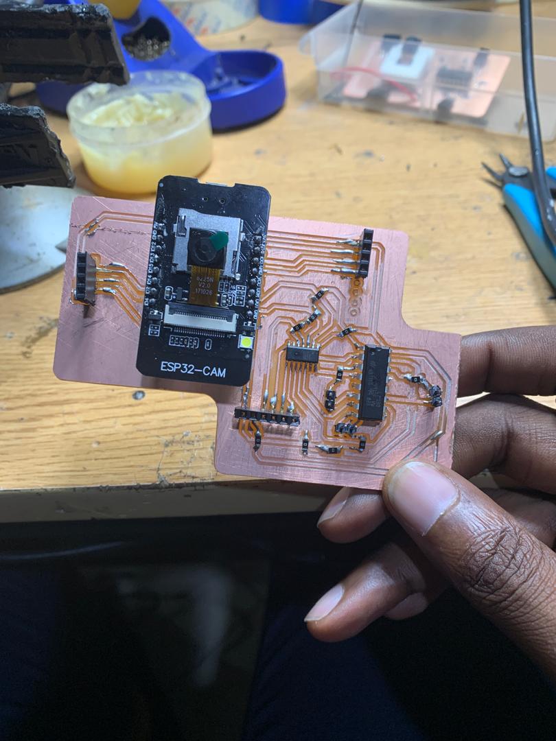
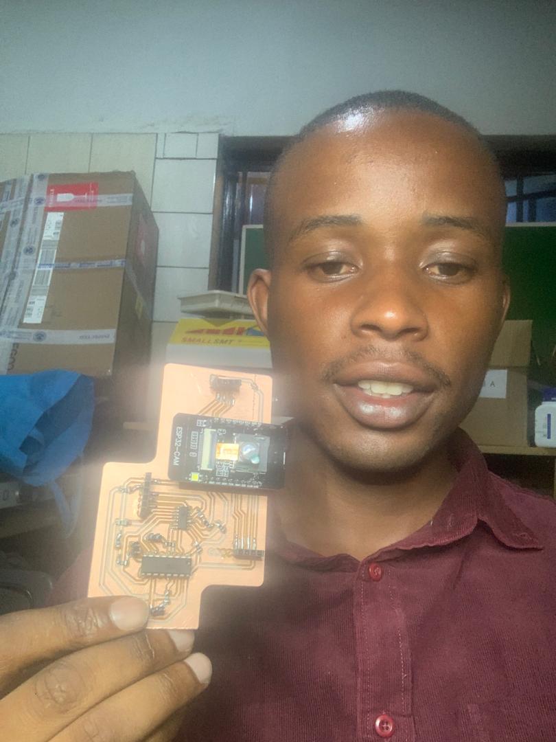
Printing PCB
Video
Wheel design and printing
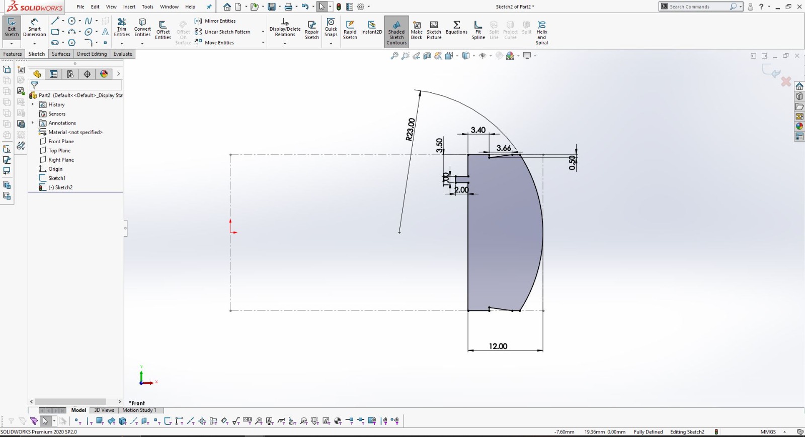
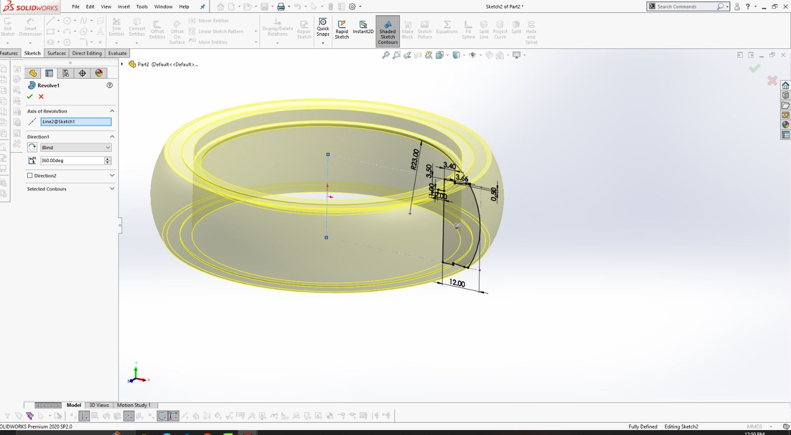
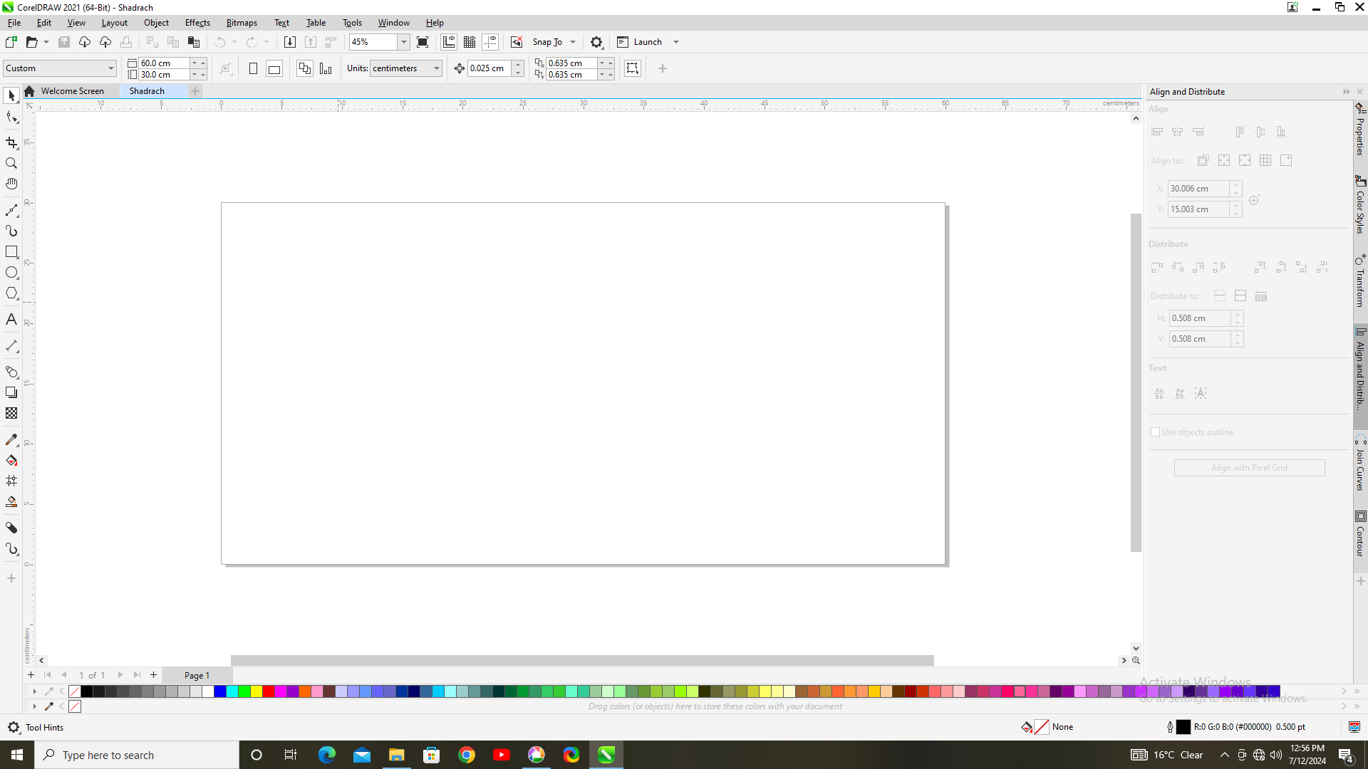
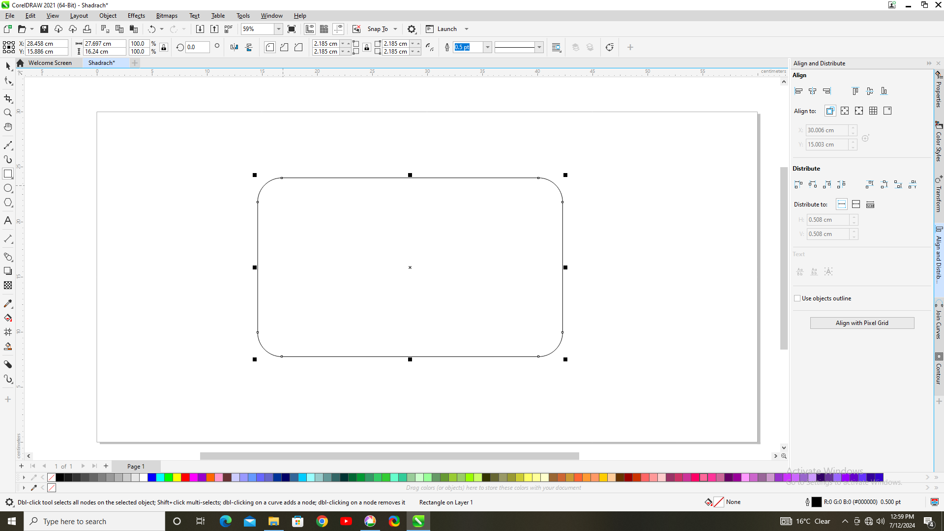
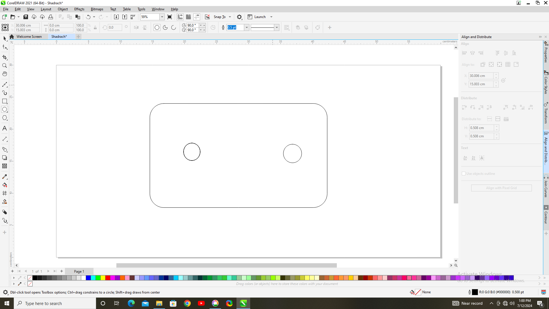
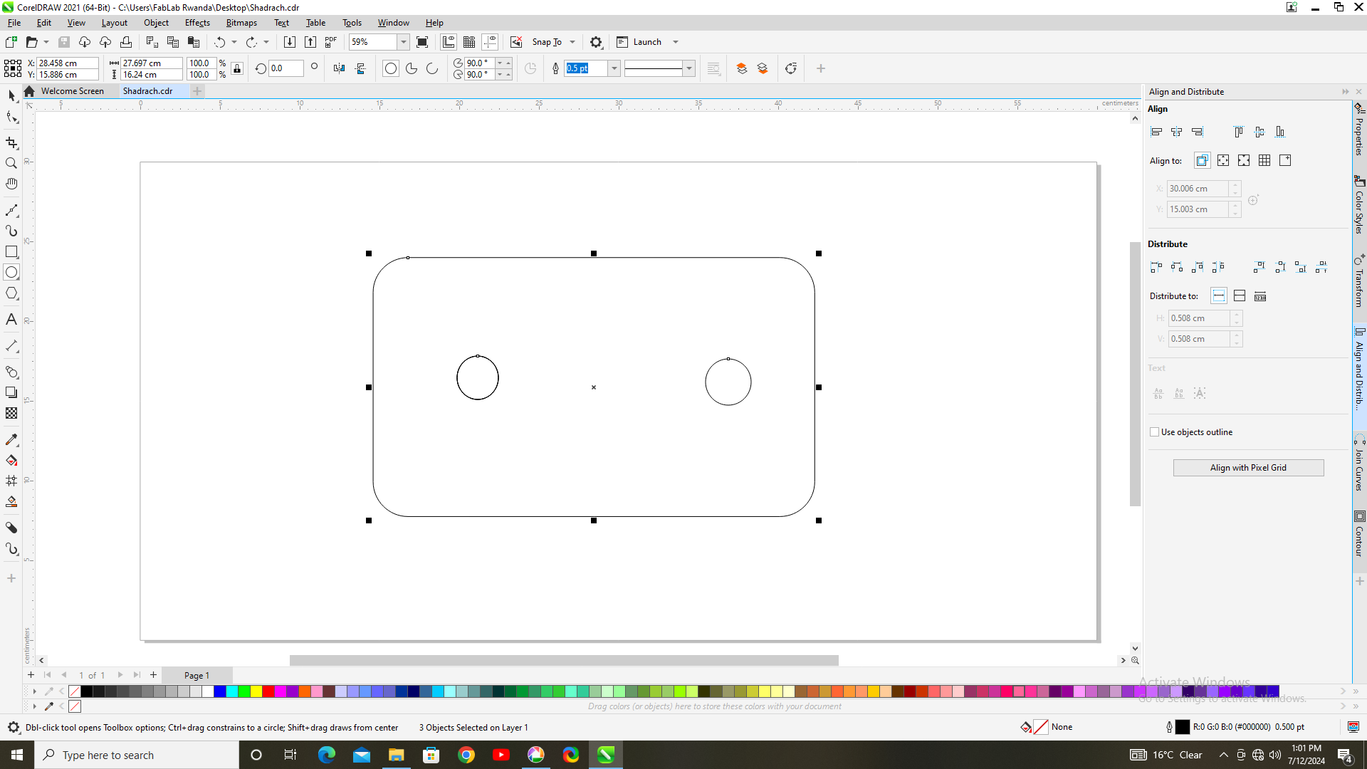
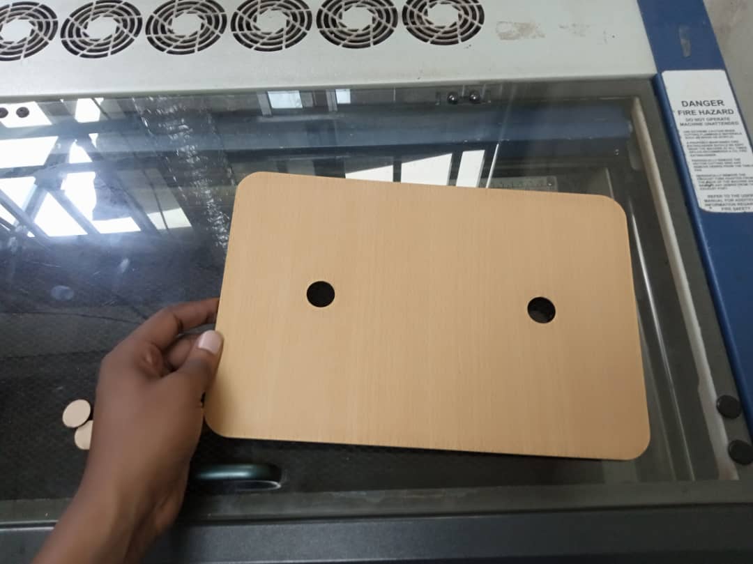
2D subtractive process
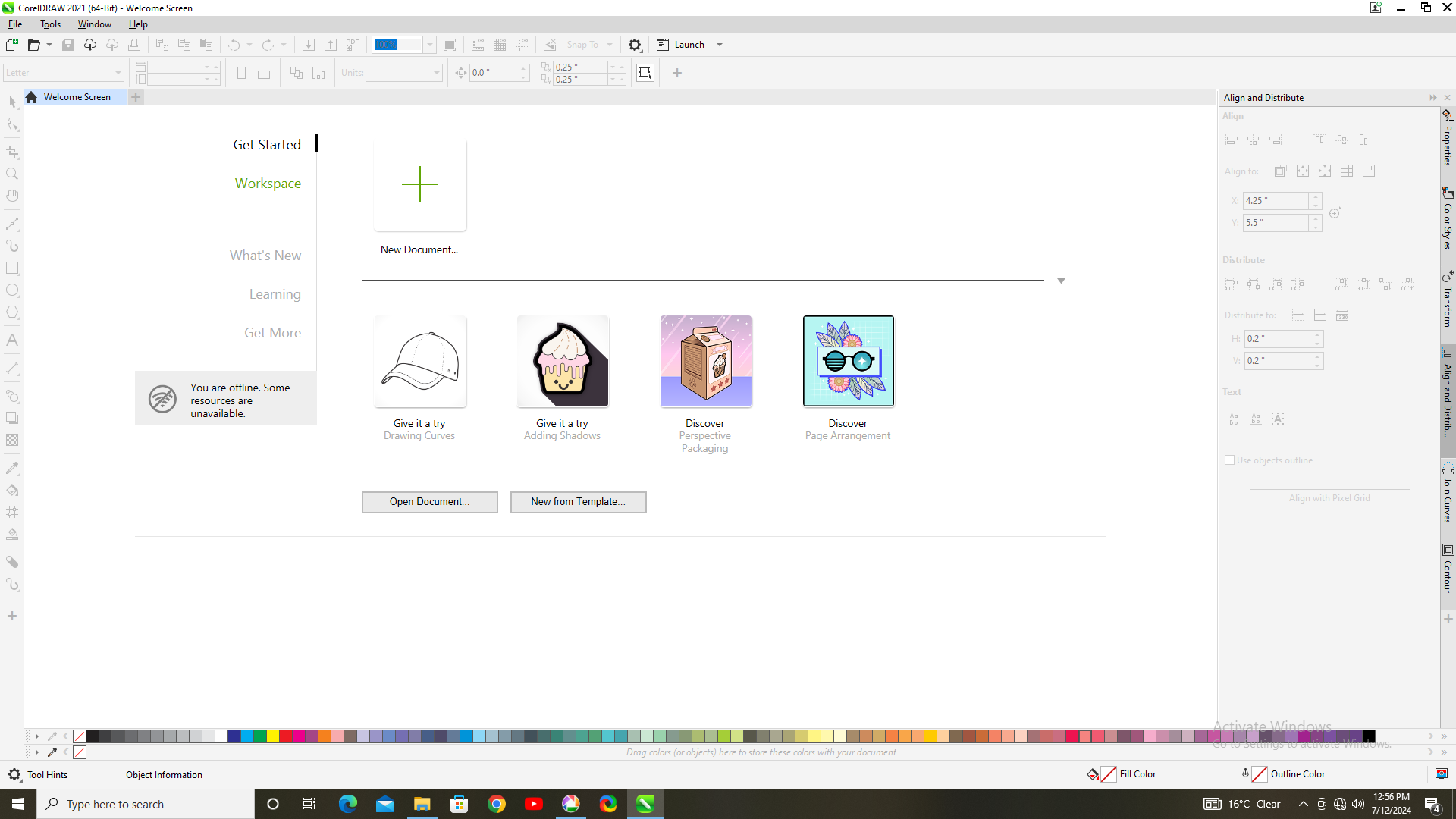
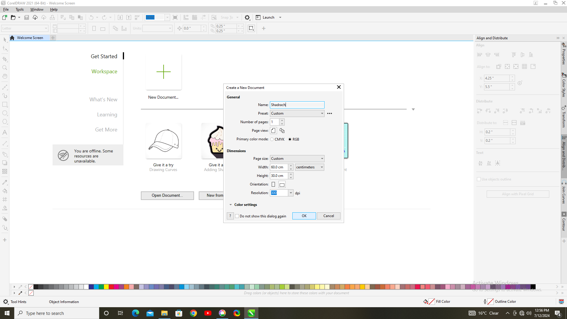
I used CorelDRAW software to create a detailed 2D design for my robotic chassis. This software is well-suited for vector graphic design, allowing me to precisely outline the components and structure of the robot. The following pictures showcase the step-by-step process and the final design of my robotic chassis created in CorelDRAW. Through this design, I was able to plan the exact dimensions and layout needed for the fabrication of the robot's parts.
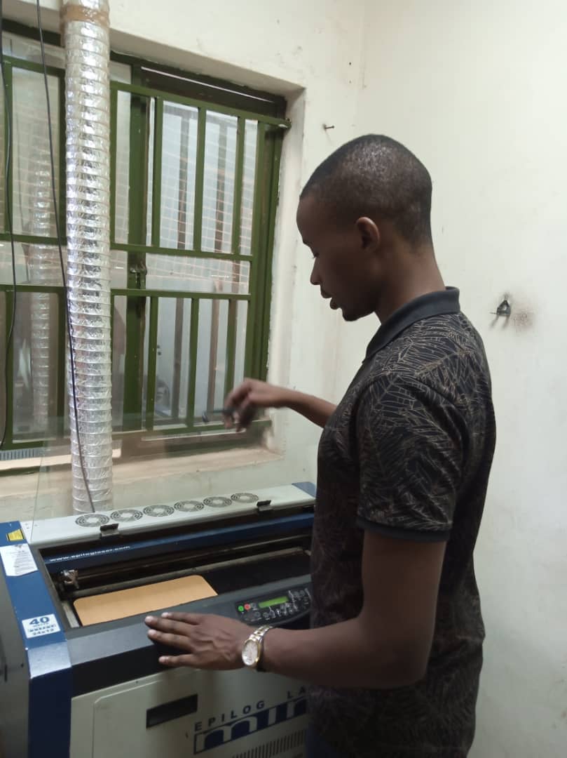
Laser Cutter Machine
I used a laser cutter machine to perform a subtractive manufacturing process on my project. This process involves removing material from a solid piece to create the desired shape and design. As you can see in the following images, the laser cutter precisely cut out the components of my project according to the 2D design I created in CorelDRAW. The laser cutter uses a high-powered laser beam to accurately cut through materials such as wood, acrylic, or metal, following the intricate paths defined in the design files. This method ensures clean, precise edges and intricate details that would be difficult to achieve with traditional cutting tools. The subtractive process is essential for creating custom parts with high precision and quality.

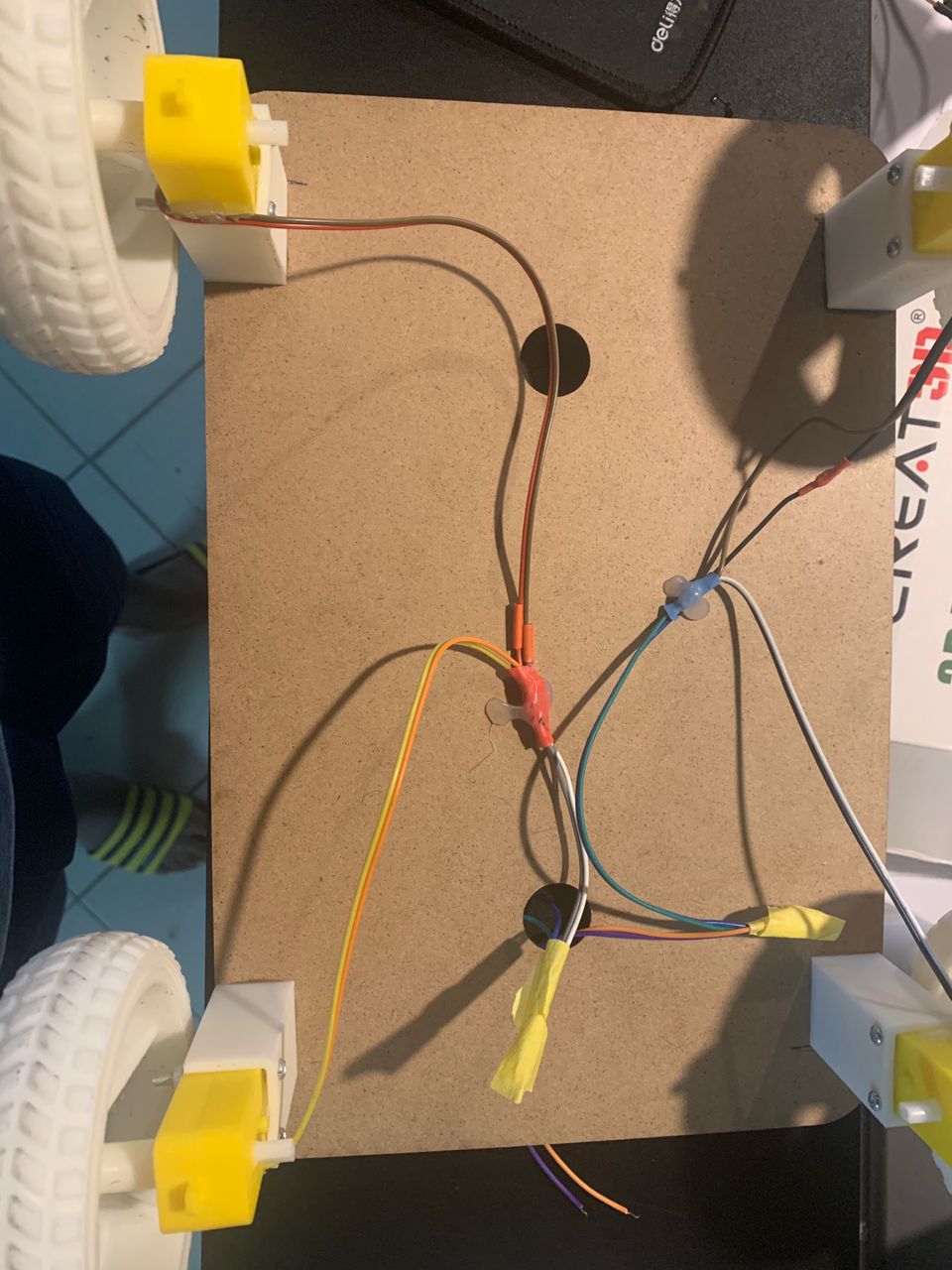
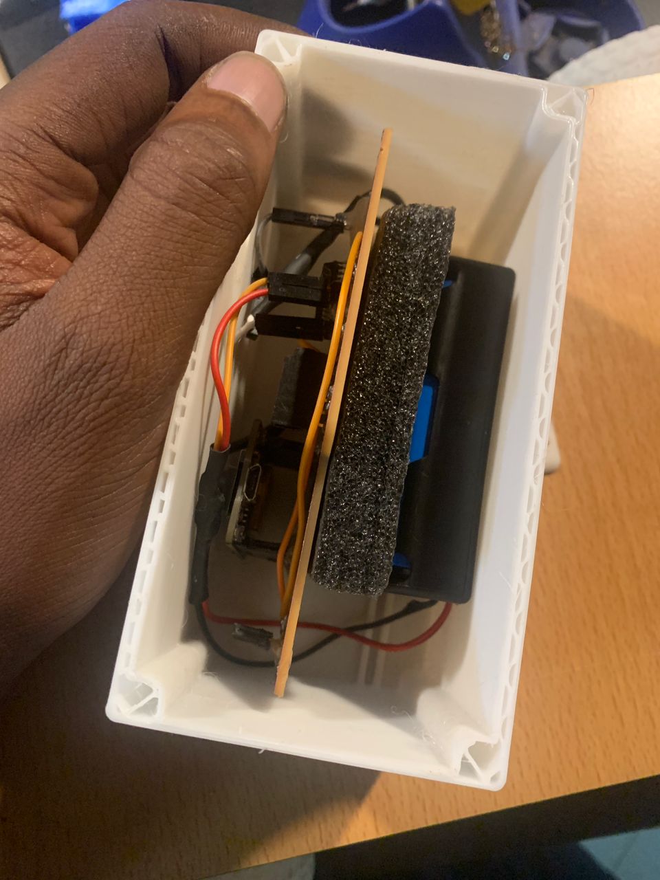
Connection process
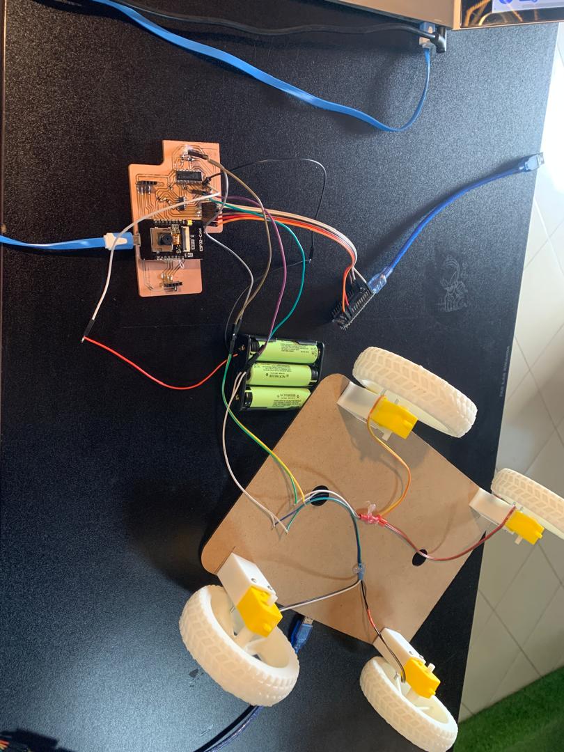
System Overview
My autonomous robot uses the ESP32-CAM as the main MCU to capture video, process it, and send commands to the ATtiny44, which controls the robot's motors and actuators. The smartphone acts as a user interface to drive the robot.
Hardware Connections
ESP32-CAM: Main MCU
- Captures video using the camera.
- Processes video data and extracts necessary information.
- Communicates with the smartphone for remote control.
- Sends control commands to the ATtiny44 via UART
ATtiny44: Motor and Actuator Controller
- Receives commands from the ESP32-CAM.
- Controls the motors and actuators of the robot based on the received commands.
Smartphone
- Connects to the ESP32-CAM via Wi-Fi.
- Sends driving commands to the ESP32-CAM.
- Receives and displays the video feed from the ESP32-CAM.
Data Flow
Video Capture and Processing
The ESP32-CAM captures video data using its camera.
The video data is processed to extract relevant information (e.g., obstacle detection, path planning).
Command Generation
Based on the processed video data and user input from the smartphone, the ESP32-CAM generates control commands.
These commands dictate the actions the robot should perform (e.g., move forward, turn left).
Communication with ATtiny44
The ESP32-CAM sends the control commands to the ATtiny44 via UART.
Example: The ESP32-CAM sends "move forward" or "turn left" commands as strings or byte data.
Motor and Actuator Control
The ATtiny44 receives the commands from the ESP32-CAM. It interprets these commands and controls the robot's motors and actuators accordingly. Example: If the command is "move forward," the ATtiny44 powers the motors to drive the robot forward.
User Interface via Smartphone
The smartphone sends user commands to the ESP32-CAM over Wi-Fi.
The ESP32-CAM processes these commands and integrates them with its autonomous functions.
The smartphone also receives the video feed from the ESP32-CAM, allowing the user to see what the robot sees.
Wiring Diagram
ESP32-CAM to ATtiny44
- ESP32-CAM GPIO17 (TX1) to ATtiny44 RX (Pin 1)
- ESP32-CAM GPIO16 (RX1) to ATtiny44 TX (Pin 0)
- Common Ground between ESP32-CAM and ATtiny44
Power Supply
- ESP32-CAM powered via 5V or 3.3V power supply.
- ATtiny44 powered via the same power supply (regulated to 5V or 3.3V as required).
Example Code
Down code below


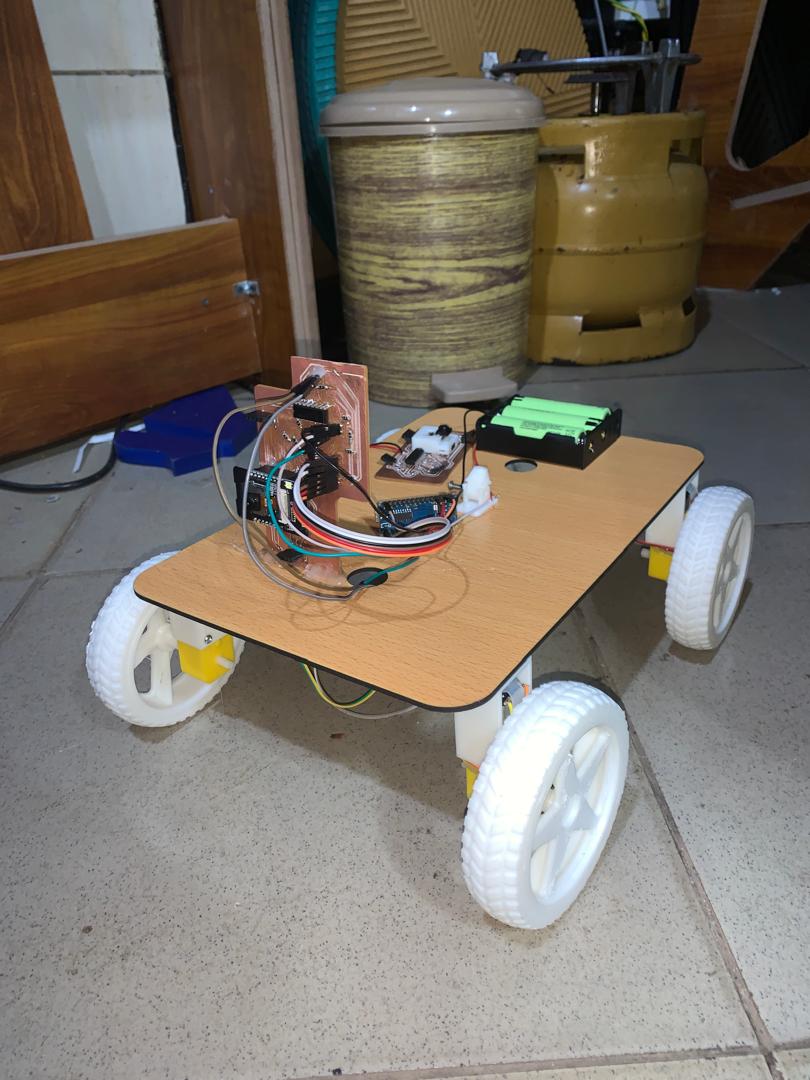
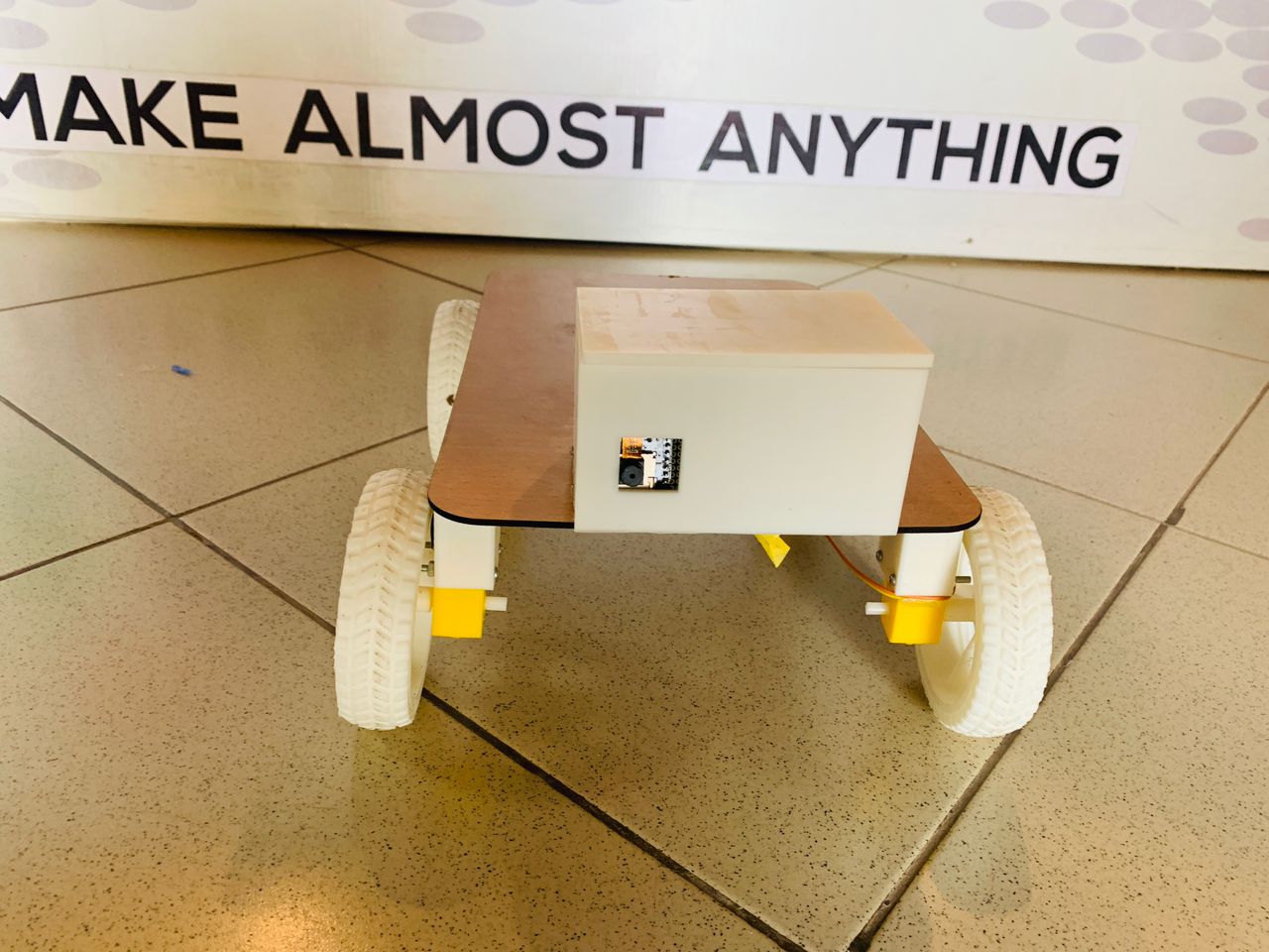
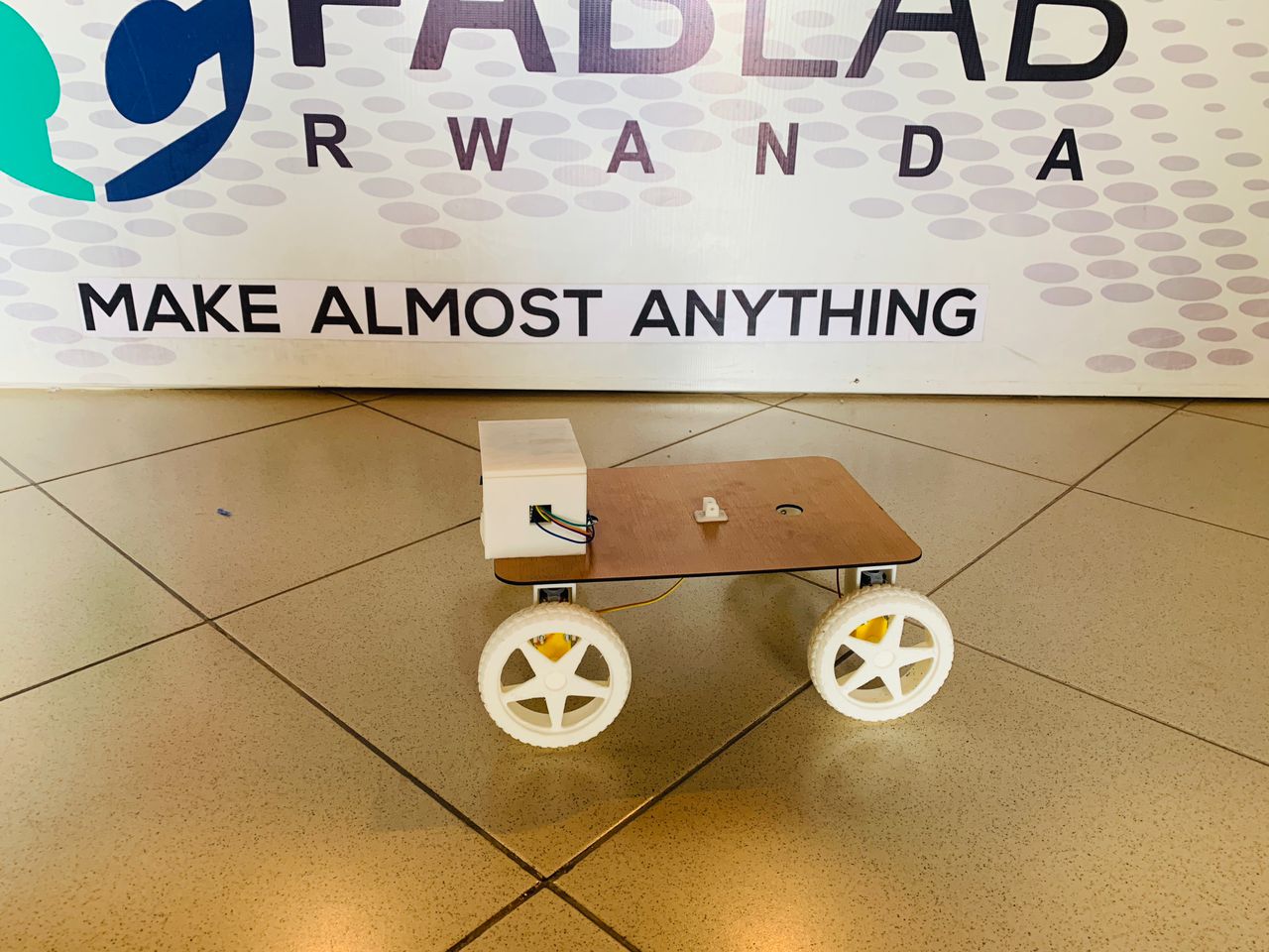
FInished Robotic
Assignment Files
download Arduino code ZIPdownload Wheels file
download EasyEDA file
download PS User Interface file
download CowelDRAW file