
Project
Autonomous 4W Rrobotics
Organization of Final Project Work
- What does it do?
- Who’s done what beforehand?
- What did you design?
- What materials and components were used?
- Where did they come from?
- How much did they cost?
- What parts and systems were made?
- What processes were used?
- What questions were answered?
- What worked? What didn’t?
- How was it evaluated?
- What are the implications?
Project Plan Outline
- Project Overview:
- Clearly define the name of your project.
- State the primary goal or outcome you aim to achieve with your project.
- Describe the boundaries and limitations of your project.
- Timeline and Milestones:
- Start Date: 12/02/2024
- End Date: 20/06/2024
- Milestones: Identify key stages or checkpoints throughout the project timeline. For example:
- Research and Conceptualization: 12/02/2024 - 12/03/2024
- Design and Prototyping: 15/03/2024 - 01/06/2024
- Testing and Iteration: 02/06/2024 - 10/06/2024
- Final Assembly and Presentation: 11-12/06/2024
Project Name: Autonomous 4W Rrobotics
What does it do?
The main goal of my final project at FabLab is to create an autonomous
four-wheel (4W) robotic system capable of capturing live video and
transmitting it to a remote interface. This allows users to control
and navigate the robot via a web browser, enhancing both accessibility
and usability. Here's a detailed breakdown:
- Objective
- Develop an autonomous robot with real-time video streaming capabilities.
- Enable remote control and navigation through a user-friendly web interface.
- Key Features:
- The robot is equipped with a camera module to capture live video footage.
- The video is transmitted to a temporary local server and accessible through a web browser.
- Users can control the robot remotely using a smartphone or computer, navigating through various environments.
- A web-based interface is designed for easy control and monitoring of the robot.
- Develop an autonomous robot with real-time video streaming capabilities.
- Enable remote control and navigation through a user-friendly web interface.
- The robot is equipped with a camera module to capture live video footage.
- The video is transmitted to a temporary local server and accessible through a web browser.
- Users can control the robot remotely using a smartphone or computer, navigating through various environments.
- A web-based interface is designed for easy control and monitoring of the robot.
Who’s done what beforehand?
My Contributions:
- I conceptualized the idea of an autonomous 4W robotic system with real-time video streaming and remote control capabilities.
- I designed the electronic circuits using EasyEDA, ensuring the proper connection and functionality of all components.
- I wrote the code for the microcontroller (ESP32-CAM) to manage video capture, transmission, and control functions.
- I created custom 3D designs for the robot's wheels and other parts, utilizing 3D printing technology.
- I integrated all the hardware and software components to build a functional prototype.
- I designed a web-based user interface for easy control and navigation of the robot via a smartphone or computer.
Inspirations and Predecessors:
- Previous Fab Academy Projects:
- Previous Fab Academy students have worked on various robotics projects, providing a foundation and inspiration for my project. For example, projects involving autonomous navigation and remote control have been explored, offering valuable insights into sensor integration and control algorithms.
- Some students have experimented with video streaming using microcontrollers, which helped me understand the challenges and solutions in real-time video transmission.
- Community Contributions:
- Platforms like GitHub and various online forums have numerous projects related to robotics and IoT, providing code snippets, circuit designs, and troubleshooting tips. These resources have been instrumental in refining my project.
- Collaboration with fellow Fab Academy participants has been crucial. Their feedback, suggestions, and shared experiences have helped me overcome technical challenges and improve my project design.
What did you design?
For my Fab Academy final project, I designed an autonomous four-wheel (4W) robotic system capable of capturing live video and transmitting it to a remote interface. The project includes several key components and subsystems, each designed to contribute to the overall functionality of the robot. Here’s a detailed breakdown of what I designed:
- Electronic Circuits:
- I designed the circuit to integrate the ESP32-CAM module for video capture and wireless communication.
- I developed the motor driver circuit to control the DC motors responsible for the robot’s movement.
- I designed the power supply circuit, including the use of batteries and a battery pack to ensure stable and reliable power for all components.
- 3D Printed Components:
- I designed and 3D printed custom wheels that provide better traction and stability for the robot.
- I designed a robust chassis to house all the electronic components securely. This included creating a compact and efficient layout for optimal performance.
- I designed a mount to securely hold the camera module, ensuring it has a clear and stable view for video capture.
- User Interface:
- I designed a user-friendly web interface that allows users to remotely control the robot using a smartphone or computer. This interface includes control buttons for movement, a live video feed from the robot’s camera, and status indicators for battery life and connectivity.
- Software Design:
- I wrote the firmware for the ESP32-CAM, enabling it to handle video capture, transmission, and motor control.
- I configured the network settings to allow seamless communication between the robot and the remote user interface, ensuring real-time control and video streaming.
- Prototyping and Testing:
- I started by sketching the design concepts on paper, detailing how the robot would look and function.
- I created multiple prototypes to test different design aspects, ensuring the final product meets all project requirements.
What materials and components were used?
| Component/Material | Description | Image | Shop | Cost in USD |
|---|---|---|---|---|
| ESP32-CAM Boards | For video capture and wireless communication |  |
Nyereka Tech | 14.4$ |
| Filament for Wheels | To 3D print durable and functional wheels | 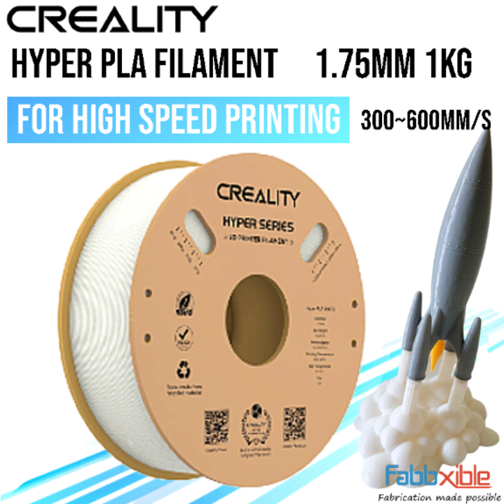 |
Nyereka Tech | 43.1$ |
| Camera for ESP32 | To capture high-quality video footage | 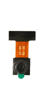 |
Nyereka Tech | 5.3$ |
| 3.7V Batteries and Battery Pack | To power the robot and its components | 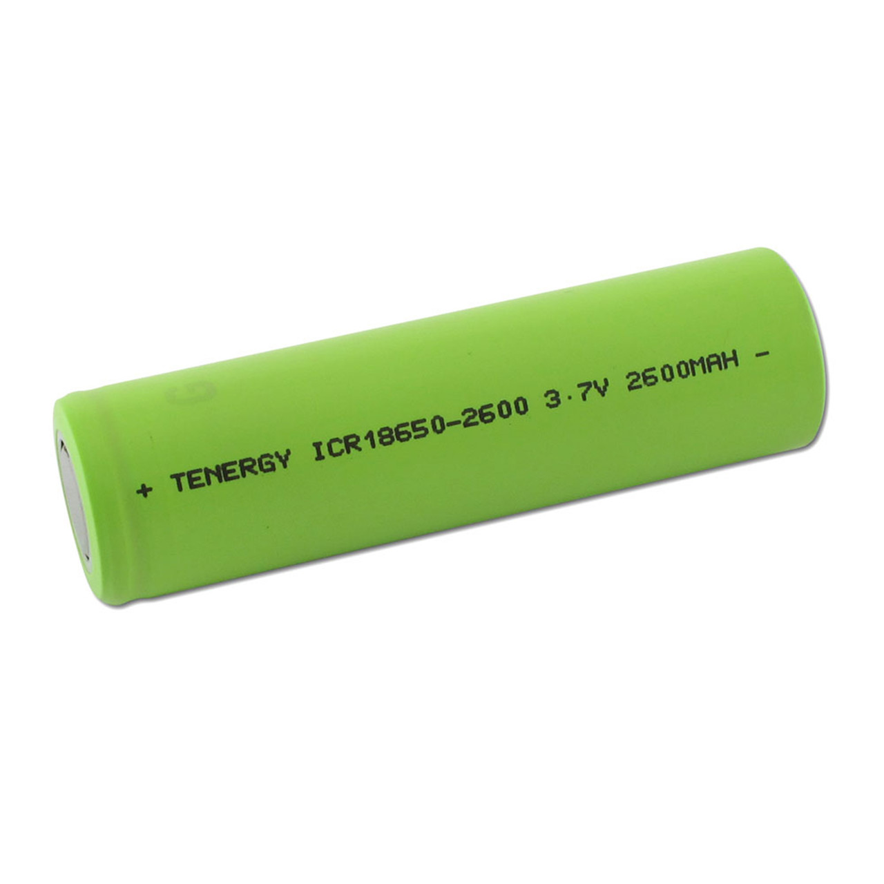 |
Nyereka Tech | 4.2$ |
| Jumper Wires | For establishing electrical connections | 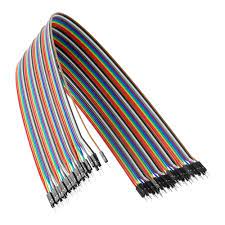 |
Nyereka Tech | 1.3$ |
| Wood for Laser Cutting | To create the chassis and other structural elements | I got this from Fablab Rwanda | From FabLab Rwanda | FabLab |
| DC Motors | To drive the wheels and enable movement | 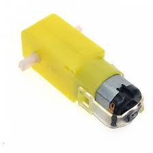 |
Nyereka Tech | 2.1$ |
| PCB | For integrating and organizing electronic components, designed using EASYEDA | 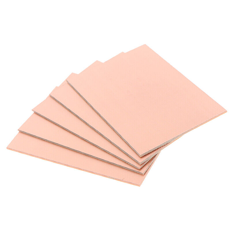 |
Nyereka Tech | 3$ |
What parts and systems were made?
Parts and Systems Made for the Autonomous 4W Robotics Project
- Chassis and Mechanical Components:
- A custom-designed and laser-cut wooden chassis to house and protect all electronic components.
- Custom-designed and 3D-printed wheels to provide better traction and stability.
- Custom mounts designed and 3D printed to securely attach the DC motors to the chassis.
- Electronic Systems:
- Integration of the ESP32-CAM module for live video capture and transmission.
- Design and implementation of a circuit to control the DC motors, enabling the robot's movement.
- A power management system including 3.7V batteries and a battery pack, ensuring stable power supply to all components.
- Custom printed circuit board (PCB) designed using EasyEDA to connect and manage all electronic components.
- Software and Firmware:
- Programming the ESP32-CAM microcontroller to handle video capture, transmission, motor control, and network communication.
- Software setup to ensure the ESP32-CAM can establish a network connection for real-time video streaming and remote control.
- User Interface:
- A user-friendly web interface that allows remote control of the robot using a smartphone or computer. This interface includes:
- Control buttons for moving the robot forward, backward, left, and right.
- A live video feed from the robot’s camera.
- Status indicators for battery life and network connectivity.
- A user-friendly web interface that allows remote control of the robot using a smartphone or computer. This interface includes:
- Prototyping and Testing:
- Detailed sketches and initial models to visualize the design and functionality of the robot.
- Multiple prototypes created to test and refine different aspects of the design, ensuring the final product meets all requirements.
What processes were used?
- Generating ideas and defining the goals and functionality of the autonomous robot.
- Creating initial sketches and drawings to visualize the design and layout.
- Choosing suitable electronic components like the ESP32-CAM, DC motors, and power supplies.
- Using EasyEDA to design the schematic and PCB layout for the electronic circuits.
- Assembling the circuits on breadboards to test their functionality before finalizing the PCB design.
- Soldering components onto the PCB to create the final electronic assemblies.
- Designing the chassis, wheels, and motor mounts using CAD software.
- Printing custom parts such as wheels and motor mounts.
- Cutting the wooden chassis components using a laser cutter for precise dimensions.
- Assembling the mechanical parts and integrating them with the electronic components.
- Writing code for the ESP32-CAM to manage video capture, motor control, and network communication.
- Developing a web-based interface using HTML, CSS, and JavaScript to allow remote control and video streaming.
- Iteratively testing the firmware and user interface to ensure reliability and performance.
- Configuring the ESP32-CAM to connect to a Wi-Fi network for real-time video streaming and remote control.
- Setting up a temporary local server to handle video streaming and user commands.
- Creating multiple prototypes to test different design aspects and refine them based on performance.
- Testing the robot in various environments to ensure it performs well under different conditions.
- Gathering feedback from potential users to improve the user interface and overall functionality.
- Keeping detailed records of the design process, including sketches, CAD models, circuit diagrams, and code.
- Creating guides and manuals to explain how to assemble, use, and troubleshoot the robot.
What questions were answered?
- The project aims to create an autonomous robot that can be remotely controlled and stream live video, enhancing surveillance and remote navigation capabilities.
- To use the available technology and resources and make feasible
- The robot will have a custom-designed wooden chassis, 3D-printed wheels, and mounts, integrating all electronic components efficiently.
- The robot will have live video streaming, remote control capabilities, and a user-friendly web interface for easy operation.
- Through a web-based interface with control buttons and live video feed.
What worked? What didn’t?
- Clearly defining the problem and objectives helped maintain focus and direction throughout the project.
- Choosing suitable components like the ESP32-CAM and DC motors that met the project's requirements.
- Initial design iterations had some mechanical flaws, such as improper alignment of motor mounts, which required redesign and reprinting.
- Encountered connectivity problems between the ESP32-CAM and the network, which required troubleshooting and additional configuration.
- Faced delays in procuring certain components, which affected the project timeline.
- Initial choice of batteries did not provide adequate power for extended operation, leading to the need for a more reliable power solution.
How was it evaluated?
- The initial sketches and plans were reviewed to ensure they were comprehensive and feasible. This included evaluating the layout of components and the overall design of the robot.
- Ensuring all selected components were compatible and met the project's requirements.
- Each 3D printed part was inspected for accuracy, strength, and fit. Any defects or issues were noted and addressed by adjusting the print settings or redesigning the parts.
- The printed circuit board (PCB) was inspected for any manufacturing defects, and continuity tests were conducted to ensure proper connections.
- Ensuring the robot responded promptly and accurately to control inputs from the web-based interface
What are the implications?
- The development of the Autonomous 4W Robotics project demonstrates significant advancements in robotics, particularly in the areas of remote control, real-time video streaming, and autonomous navigation.
- The successful integration of IoT components like the ESP32-CAM and embedded systems highlights the potential for creating more sophisticated and interconnected robotic solutions.
- The project serves as an excellent educational tool, providing hands-on experience in electronics, programming, and mechanical design. It can inspire students and enthusiasts to explore robotics and embedded systems further.
- Incorporating such projects into the Fab Academy curriculum can enrich the learning experience, offering students practical applications of their theoretical knowledge.
- The robot's ability to capture and stream live video makes it an ideal candidate for security and surveillance applications. It can be deployed in high-risk or hard-to-reach areas, providing real-time monitoring and control.
- The robot can be used for remote inspection and maintenance tasks in various industries, reducing the need for human presence in potentially hazardous environments.
- The project showcases a potential product that could be commercialized for use in security, surveillance, remote monitoring, and other applications. It opens up new market opportunities for companies specializing in robotics and IoT solutions.
- The modular nature of the robot allows for customization to meet specific industry needs, making it a versatile solution for various market segments.
- By deploying the robot in hazardous environments, human exposure to dangerous situations can be minimized, enhancing safety in industrial, military, and disaster response scenarios.
- Sharing the project details, designs, and code with the broader community can foster collaboration and innovation. It encourages other developers and researchers to build upon the work, leading to further advancements in robotics.
- The project lays the groundwork for future enhancements, such as improved autonomy, advanced sensors, and AI integration. Continued research and development can lead to more capable and intelligent robotic systems.