WEEK 9: OUTPUT DEVICES
Output device: An output device is any device that receives data from a computer and presents or displays it to the user in a human-readable format.
Output devices convert electronic information into human-readable form. Common output devices include: Displays, Speakers, Actuators like motors and others.
Group Work
What to do
add an output device to a microcontroller board you've designed, and program it to do something.
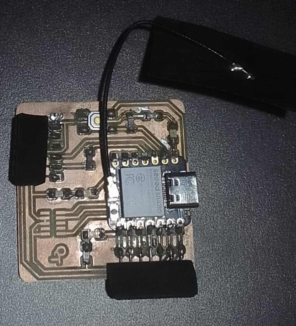
In this assignment, our group measured the power consumption of an output device. We used our custom board and a mini stepper motor programmed to move in steps forward and backward.The group work page click here.
Individual Reflection:
- Importance of Accurate Measurements: Measuring current and voltage accurately is crucial to determining the power consumption of a device. I learned how to properly set up and use a multimeter for these measurements.
- Understanding Power Consumption: I gained a better understanding of how power consumption varies with the operation of the device. For instance, the current draw of the stepper motor varied depending on its movement and load.
- Practical Application of Theory: The assignment helped bridge the gap between theoretical knowledge and practical application. Calculating power consumption using real-world measurements reinforced my understanding of electrical principles.
- Collaboration and Documentation: Working as part of a group emphasized the importance of collaboration and clear documentation. Sharing our findings and documenting the process on the group work page ensured that our work could be understood and replicated by others.
Individual work
This week's activity is to add an output device to a microcontroller board i have designed, and program it to do something.
Designed board I used for my work, Inspired by Quentorres.
I. I2C Liquid Crystal Display as an output device
I2C (Inter-Integrated Circuit) Liquid Crystal Displays (LCDs) are a type of LCD screen that can be controlled using the I2C protocol. I2C is a serial communication protocol commonly used to connect low-speed peripherals to microcontrollers and other embedded devices.
I2C LCDs typically consist of a standard LCD screen combined with a small circuit board that includes an I2C interface chip. This chip handles the communication between the LCD screen and the microcontroller, simplifying the connection and control of the LCD.
Using I2C with an LCD allows you to control the display using only two wires (plus power and ground). It also simplifies the software interface, as many libraries and code examples are available for using I2C LCDs with various microcontrollers and development boards.
Code development.
I. used the library code Arduino IDE.
                  //LCD Screen as an output device for display

                  LCD_I2C lcd(0x27, 16, 2); // Default address of most PCF8574 modules, change according

                  void setup()
                  {
                      lcd.begin(); // If you are using more I2C devices using the Wire library use lcd.begin(false)
                                   // this stop the library(LCD_I2C) from calling Wire.begin()
                      lcd.backlight();
                  }

                  void loop()
                  {
                      lcd.print("     Thank you"); // You can make spaces using well... spaces
                      lcd.setCursor(5, 1); // Or setting the cursor in the desired position.
                      lcd.print("All!");
                      delay(500);

                      // Flashing the backlight
                      for (int i = 0; i < 5; ++i)
                      {
                          lcd.backlight();
                          delay(50);
                          lcd.noBacklight();
                          delay(50);
                      }

                      lcd.backlight();
                      lcd.clear();
                      delay(500);
                  }
The output can be seen in the video below.
II. Stepper motor as an output device
The output work focuses on controlling a stepper motor using the L293D Motor Driver Board, with the motor connected to pins M3 and M4 on the board. The L293D Motor Driver Board is a popular choice for driving stepper motors as it provides the necessary power and control signals.
Stepper motors are widely used in various applications, from robotics to 3D printers, due to their precise control over rotation.
  //Code will be  here.
  #include <AFMotor.h>

    // Create a motor object for motor port #2 (M3 and M4)
    AF_Stepper motor(200, 2); // 200 steps per revolution, motor port #2 (M3 and M4)

    void setup() {
      Serial.begin(9600);           // set up Serial library at 9600 bps
      Serial.println("Starting motor operation...");

      motor.setSpeed(10);  // 10 rpm
    }

    void loop() {
      // Run the motor forward
      Serial.println("Forward");
      motor.step(100, FORWARD, SINGLE);
      delay(1000); // Wait for 1 second

      // Stop the motor
      Serial.println("Stop");
      motor.release();
      delay(1000); // Wait for 1 second

      // Run the motor backward
      Serial.println("Backward");
      motor.step(100, BACKWARD, SINGLE);
      delay(1000); // Wait for 1 second

      // Stop the motor
      Serial.println("Stop");
      motor.release();
      delay(1000); // Wait for 1 second
    }
The following is the video showing the output.
I used an L293D Motor Driver Board to control my 17HS4401 stepper motor. The motor is powered by a 9V power supply, while the microcontroller is powered via USB from my computer. The motor operates in a sequence: it runs in the forward direction for 1 second, stops for one second, then runs backward for one second, and stops for another second. This cycle repeats continuously.
III. DC Motor as anoutput device
MY DC motor is connected to pin M4 on the L293D Motor Driver Board. The code developed can be found below;
                  #include  <AFMotor.h>

                    // Create a motor object for motor port #2 (M3 and M4) on the Motor Driver Board
                    AF_DCMotor motor(4);

                    void setup() {
                      Serial.begin(9600);           // set up Serial library at 9600 bps
                      Serial.println("Motor test!");

                      motor.setSpeed(255);  // Set the speed (0 to 255)
                    }

                    void loop() {
                      // Run the motor forward
                      Serial.println("Forward");
                      motor.run(FORWARD);
                      delay(2000); // Run for 2 seconds

                      // Stop the motor
                      Serial.println("Stop");
                      motor.run(RELEASE);
                      delay(1000); // Stop for 1 second

                      // Run the motor backward
                      Serial.println("Backward");
                      motor.run(BACKWARD);
                      delay(2000); // Run backward for 2 seconds

                      // Stop the motor
                      Serial.println("Stop");
                      motor.run(RELEASE);
                      delay(1000); // Stop for 1 second
                    }
The code controls a DC motor connected to pin M4 on the L293D Motor Driver Board. It sets up the motor speed and then runs the motor in a sequence: forward for 2 seconds, stops for 1 second, backward for 2 seconds, and stops for 1 second. This cycle repeats continuously. The AFMotor library is used to control the motor direction and speed.
Output in the video below