Computer-controlled cutting
CONTENT
Vinyl Cutter
Lazer Cutter
1. VINYL CUTTER
Definitions
VINYL CUTTER:A vinyl cutter is a device used to precisely cut vinyl sheets or rolls into specific shapes or designs.
To use vinyl cutter, I had to have a software to use. Then, I received a setup of CutStudio to install on my computer
CutStudio: CutStudio is a software program developed by Roland DG Corporation, primarily designed for controlling Roland vinyl cutters. It's commonly used in conjunction with Roland vinyl cutting machines to create designs, adjust settings, and send cutting instructions to the cutter.
I started with installation of CutStudio.
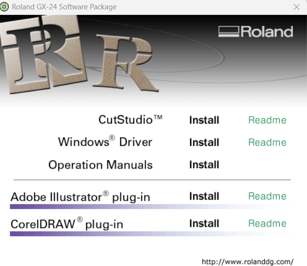
I installed CutStudio and windows drivers that runs the type of machine we have at fablab Rwanda
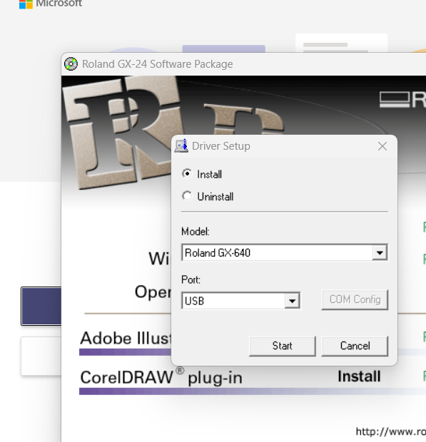
Installed drivers; For us we selected Roland GX-64 for the type of our machine.Making sure the machine is connected to the computer with the cable.
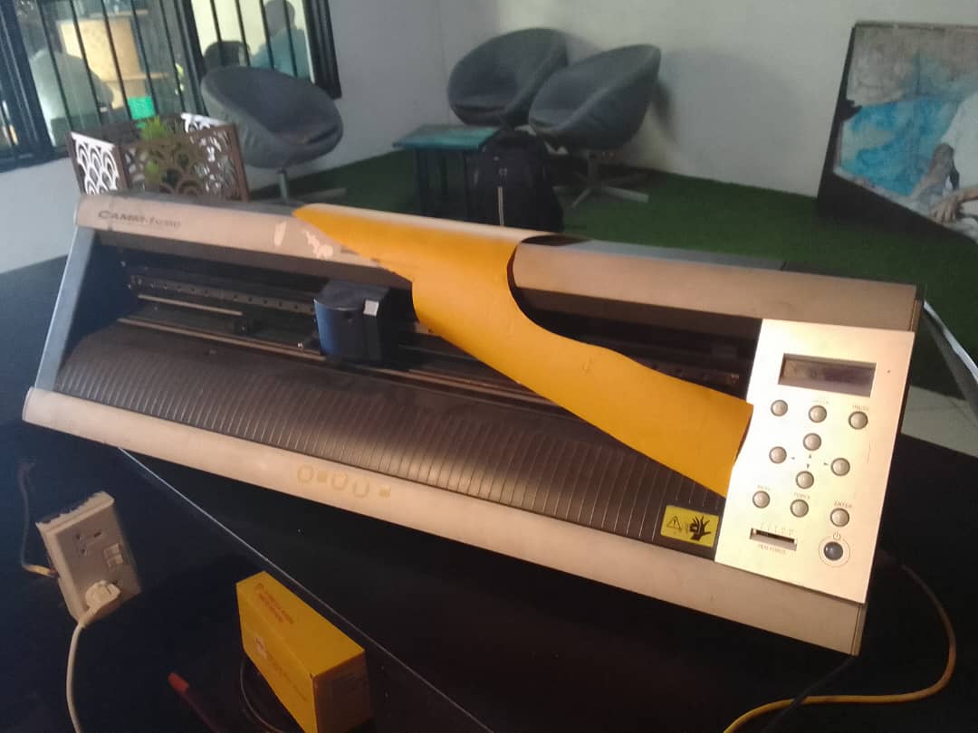
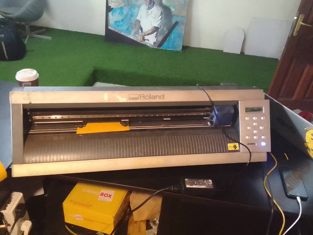
We have GX 24 Model Roland Vinyl Cutter.
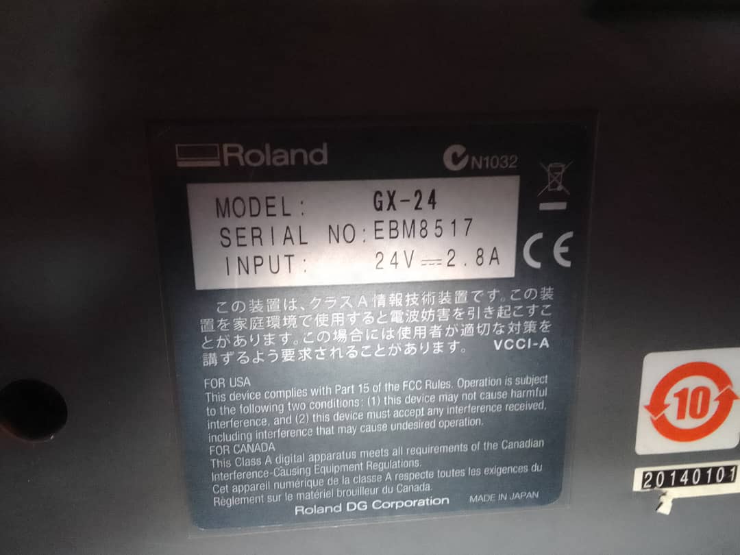
Specifications of our machine as shown on the above image.
Using Roland Vinyl Cutter with CutStudio
The first step to was to design in CutStudio. For me, i important JPG image of the logo of my compay STES Group Ltd.
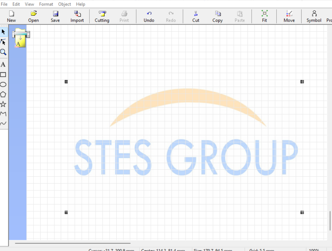
The image is now imported in CutStudio.

Next step was to edit the image for contourlines to cut through tool bar to objects then click image outline.
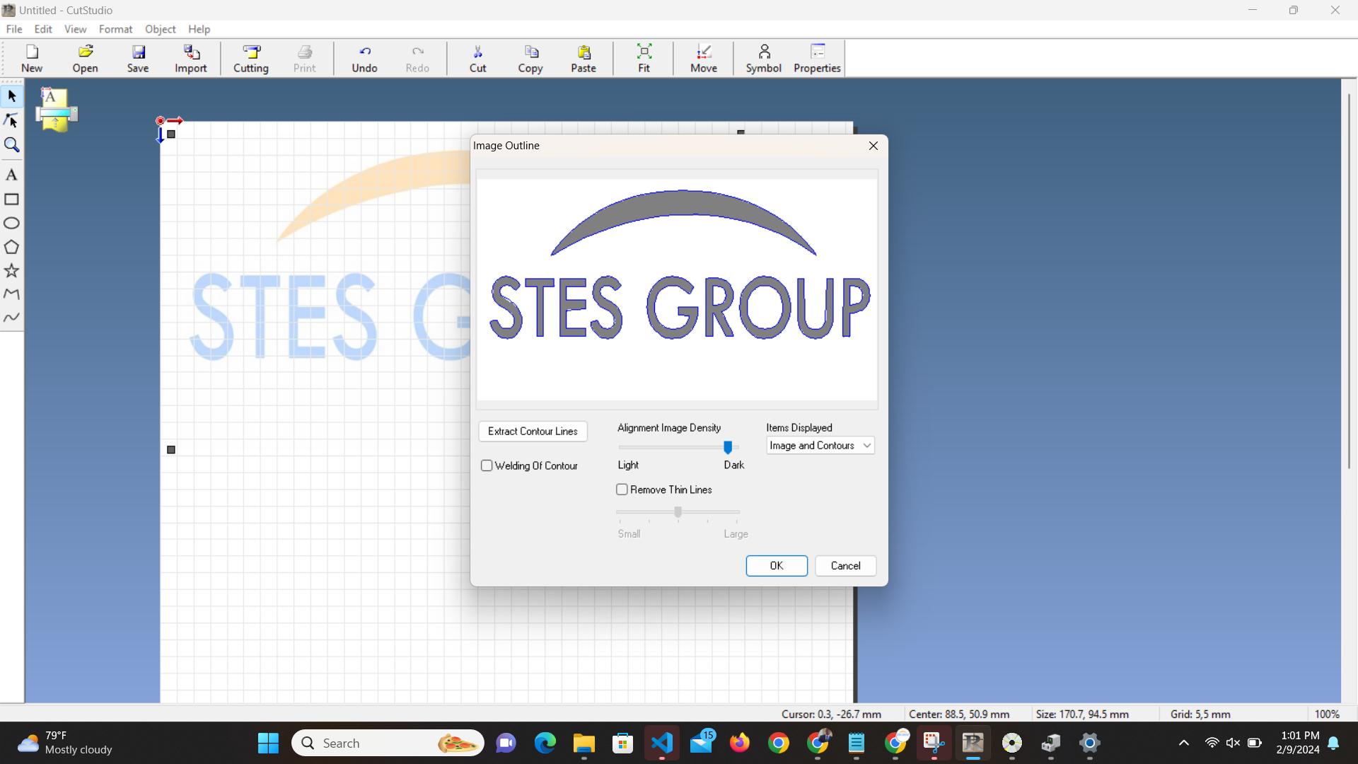
Now the Item display is set to contours only and reduced density of contours to make only contour lines visible and then click ok.
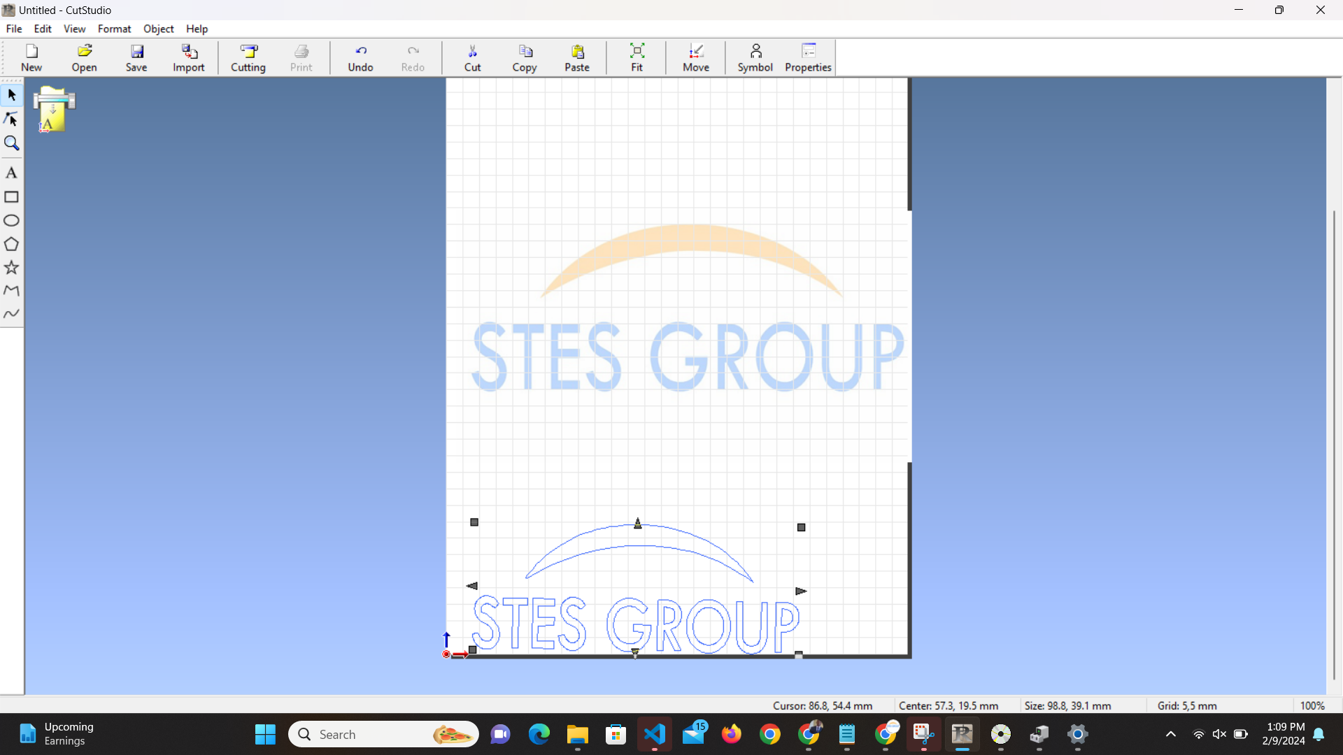
Now the final work is done. The next step is to go the the machine to launch the cutting.
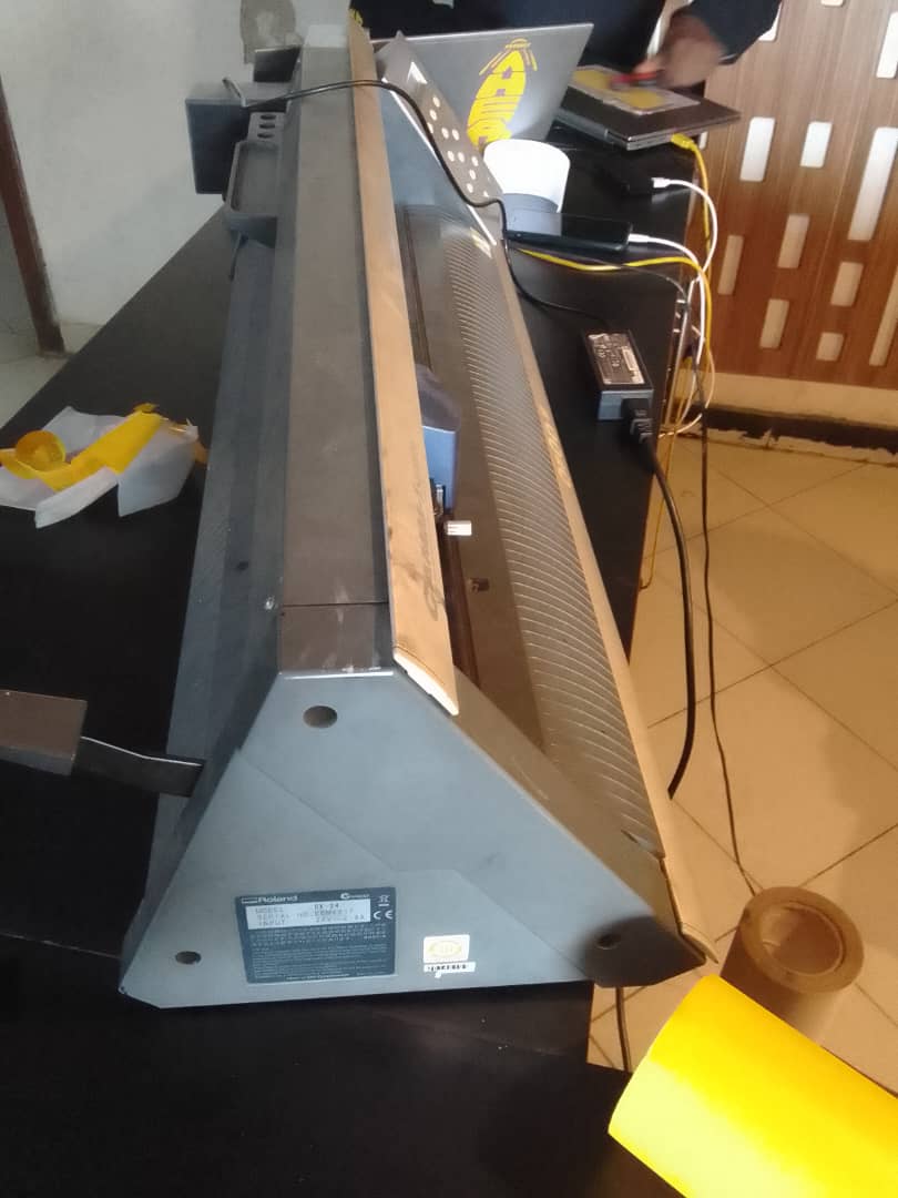
Roland GX-24 Model I used
Inserted a piece of vinyl into the machine, then turnon the machine and set the printing material to piece. The machine automatically measures the size of the material, Width and Lenght.
Then set the area in CutStudio as taken from the piece by the machine. Making sure the machine is connected to my computer.
Next step is to start printing and cut the part printed from the vinyl piece.
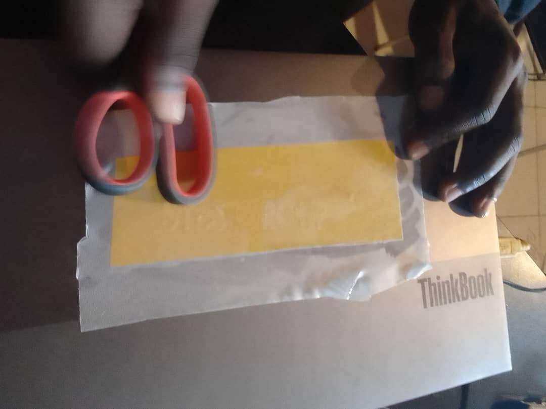
Attaching the vinyl piece on the sticker.
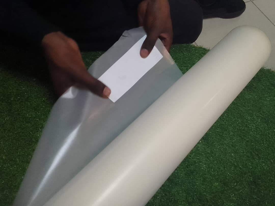
Attach the vinyl onto the sticker as shown in the image above.
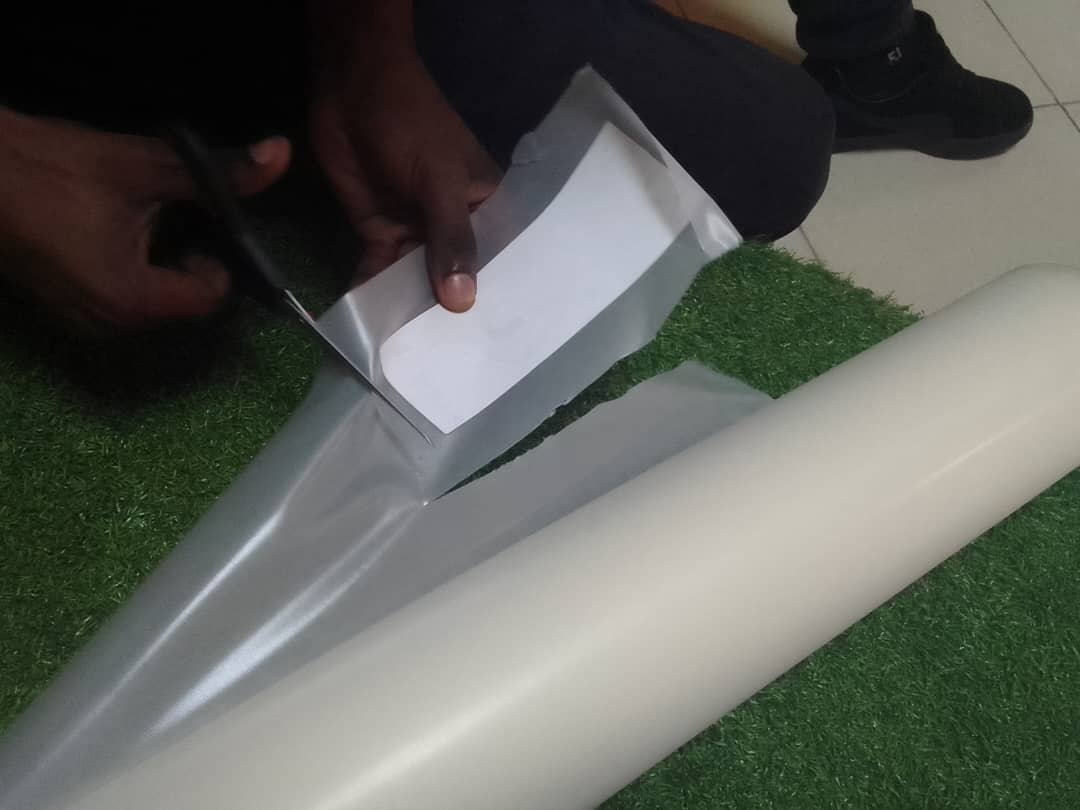
After fixing well then start cutting the piece from the rol of the sticker.
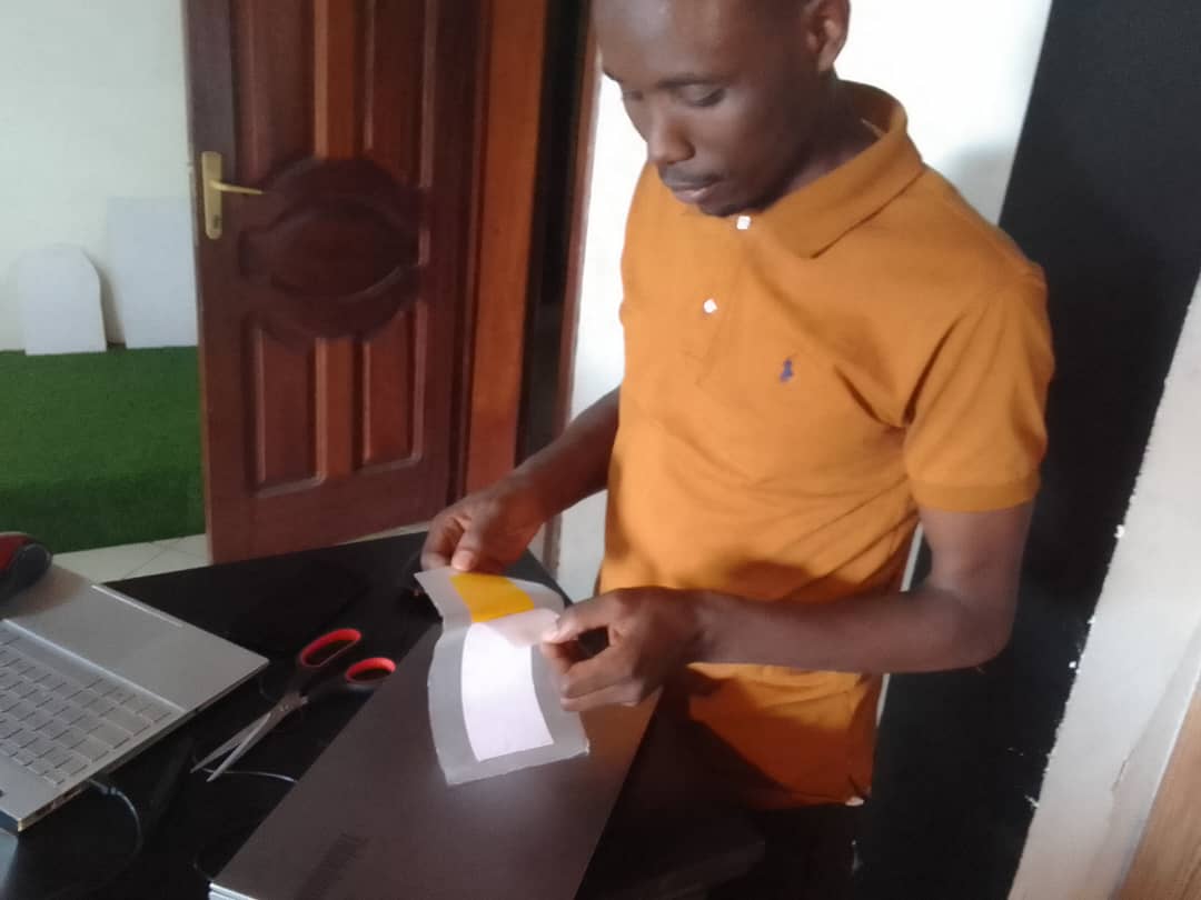
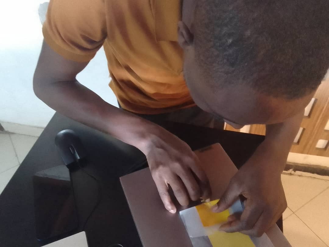
Preparing to fix the piece on my computer.
Fixing the piece on my computer with pressure to stick hard.
Start removing the sticker with unwanted parts, remaining with only the printed parts.
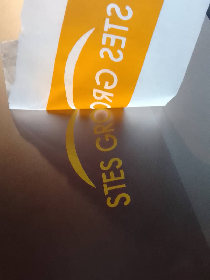
Continue removing with patience.

Now finish with removing the sticker and unwanted parts.
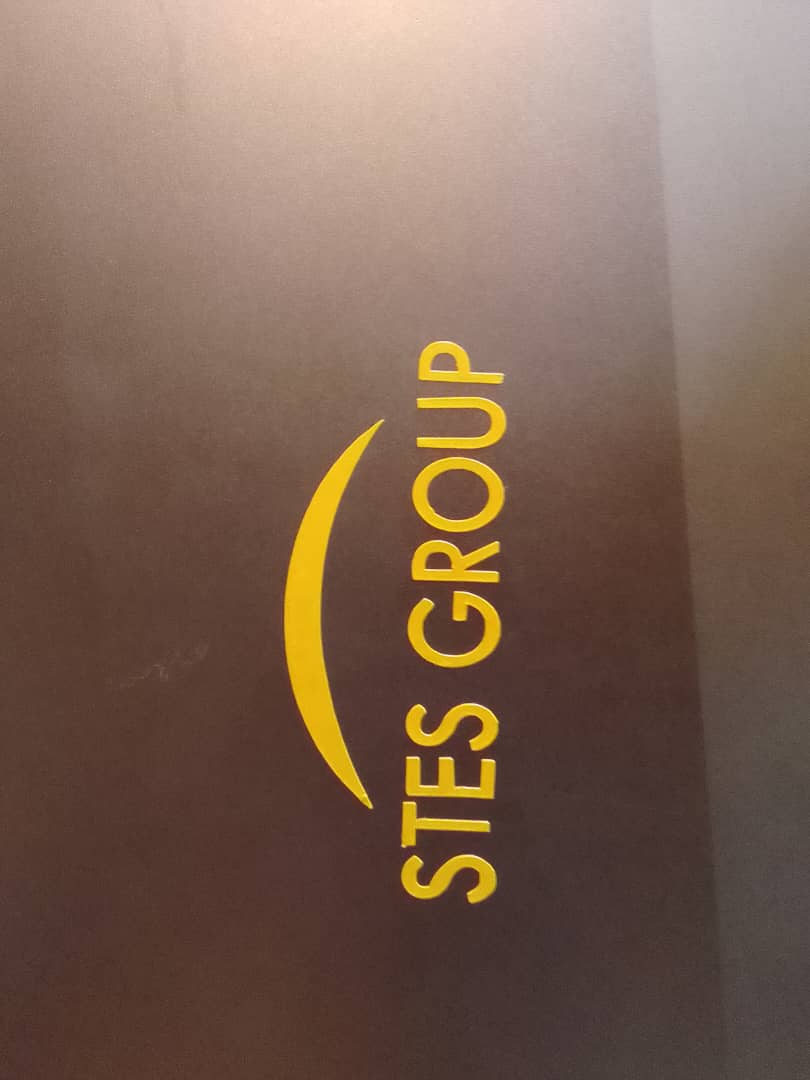
This is the finished design of Vinyl Cutter on my personal computer I have done for myself.
2. LAZER CUTTER
Software for 2D Design:
The software used for the 2D design is AutoCAD.
Parametric Designing with “Kerf”:
Parametric designing with "Kerf" is crucial for this week's assignment. The kerf is the amount of material removed by the laser cutter, which affects the fit of the parts.
Value of the Kerf and Testing in Group Assignment:
For the group assignment, we tested the kerf value using different cuts and measurements. The kerf value we determined was 0.2mm. This was tested by cutting several samples and measuring the actual dimensions of the cuts compared to the design dimensions.
Using Kerf as a Parameter to Fit the Joint:
We used the kerf as a parameter to ensure the joints fit properly. The parameter "material_thickness" was set to the thickness of the MDF sheet, which is 2.5mm, and the kerf value was used to adjust the design to ensure a snug fit. For example, when designing slots or tabs, we subtracted the kerf value from the slot width to account for the material removed by the laser.
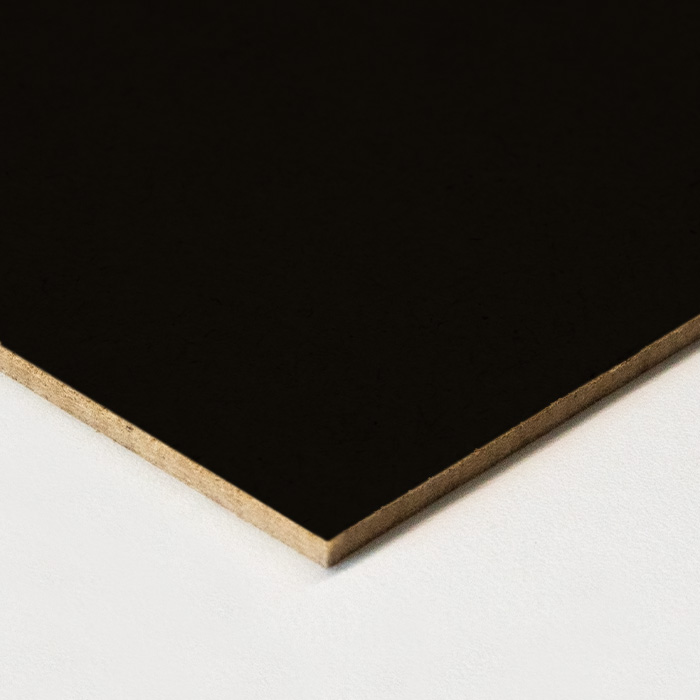
MDF board with a black coating on one side with 2.5mm Thickness
Measuring Thickness with Vernier Caliper
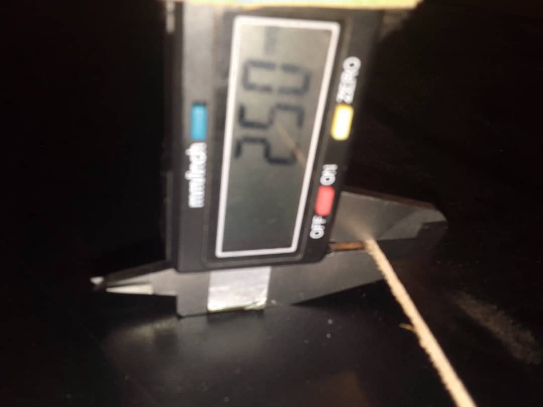
Table of Formulas with Kerf:
| Parameter | Formula | Value | Description |
|---|---|---|---|
| Slot Width | material_thickness - kerf | 2.5mm - 0.2mm = 2.3mm | Width of the slot adjusted for kerf |
| Tab Width | material_thickness + kerf | 2.5mm + 0.2mm = 2.7mm | Width of the tab adjusted for kerf |
| Cut Length | design_length - (kerf * number_of_cuts) | 63mm - (0.2mm * 4) = 62.2mm | Total cut length adjusted for multiple kerfs |
| Joint Fit | design_dimension - kerf | 63mm - 0.2mm = 62.8mm | Dimension adjusted for joint fit |
Start of Development
The week started with understanding how a drawing software interfaces to a lazer cutting machine.
Parametric design is a process in architecture and engineering where algorithms are used to define and manipulate design parameters, allowing for the creation of complex structures and forms that can be easily adjusted and optimized by altering these parameters.
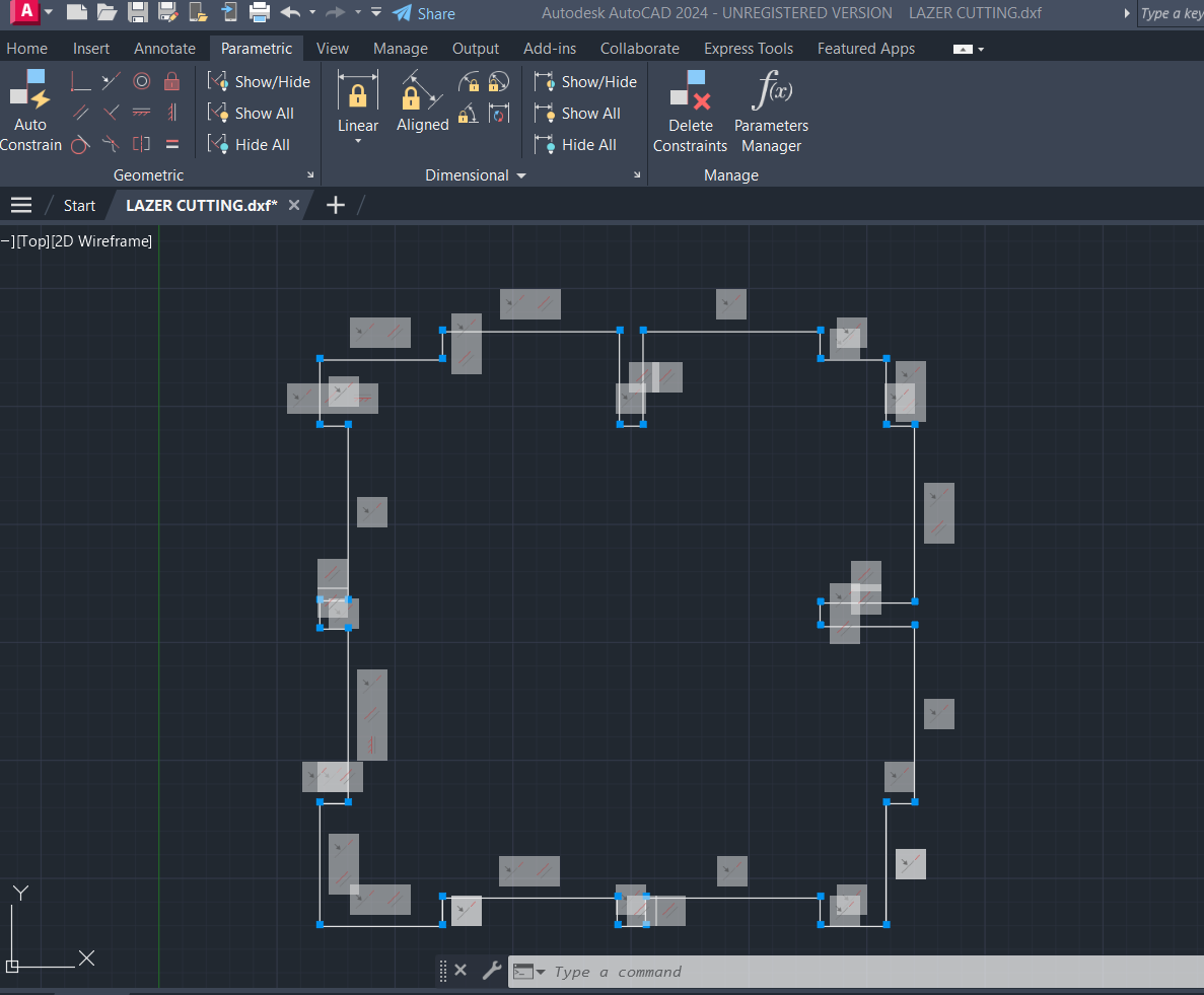
Parametric Design

After creating a simple model, the easiest way to apply constraints to it is to use the Auto Constrain button.
Here is a detailed video of how it works
After selecting Auto Constrain command you can select the objects in your model that you want to constrain.
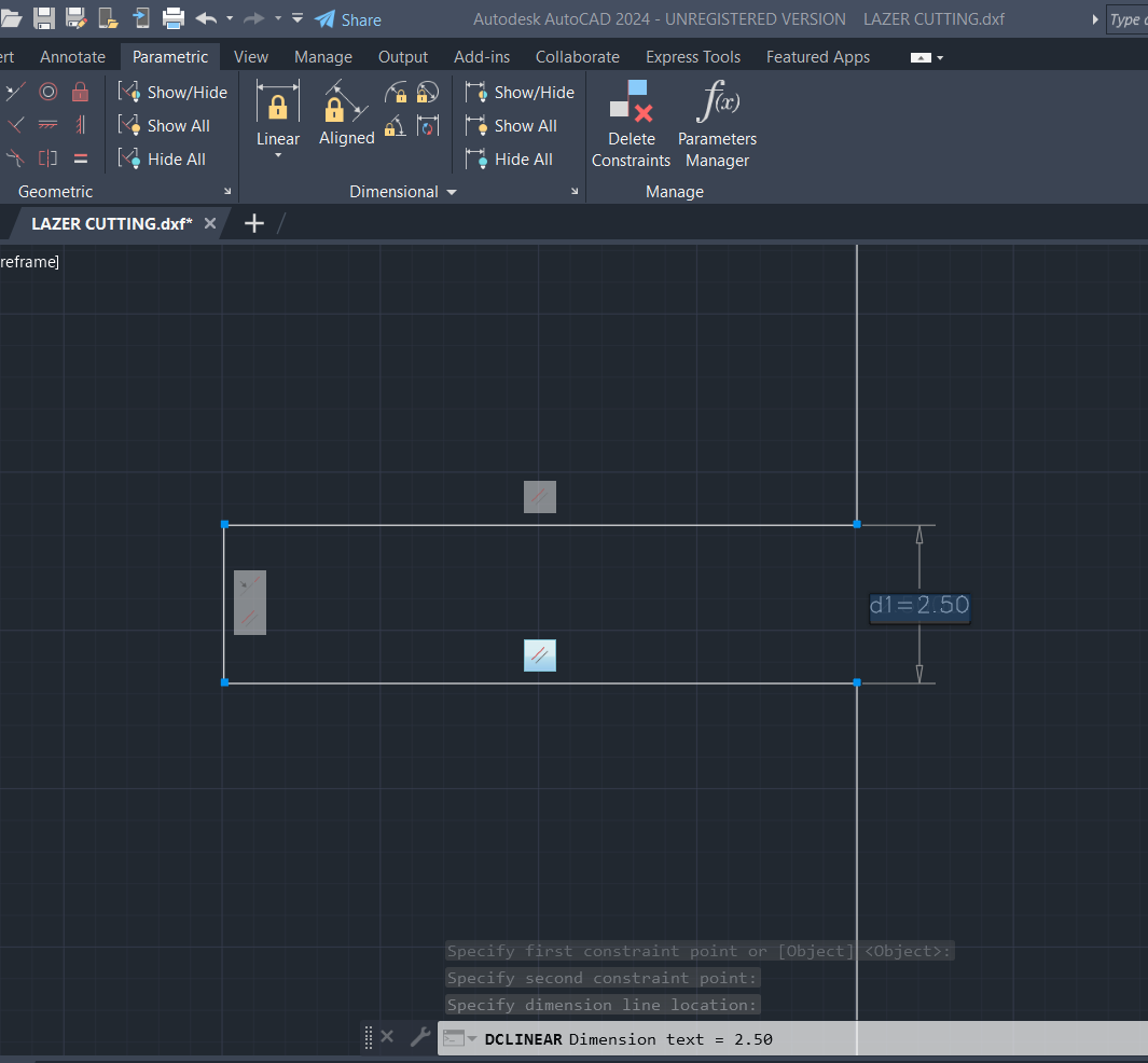
Forexample you can edit dimensions and constrained parts change with it.
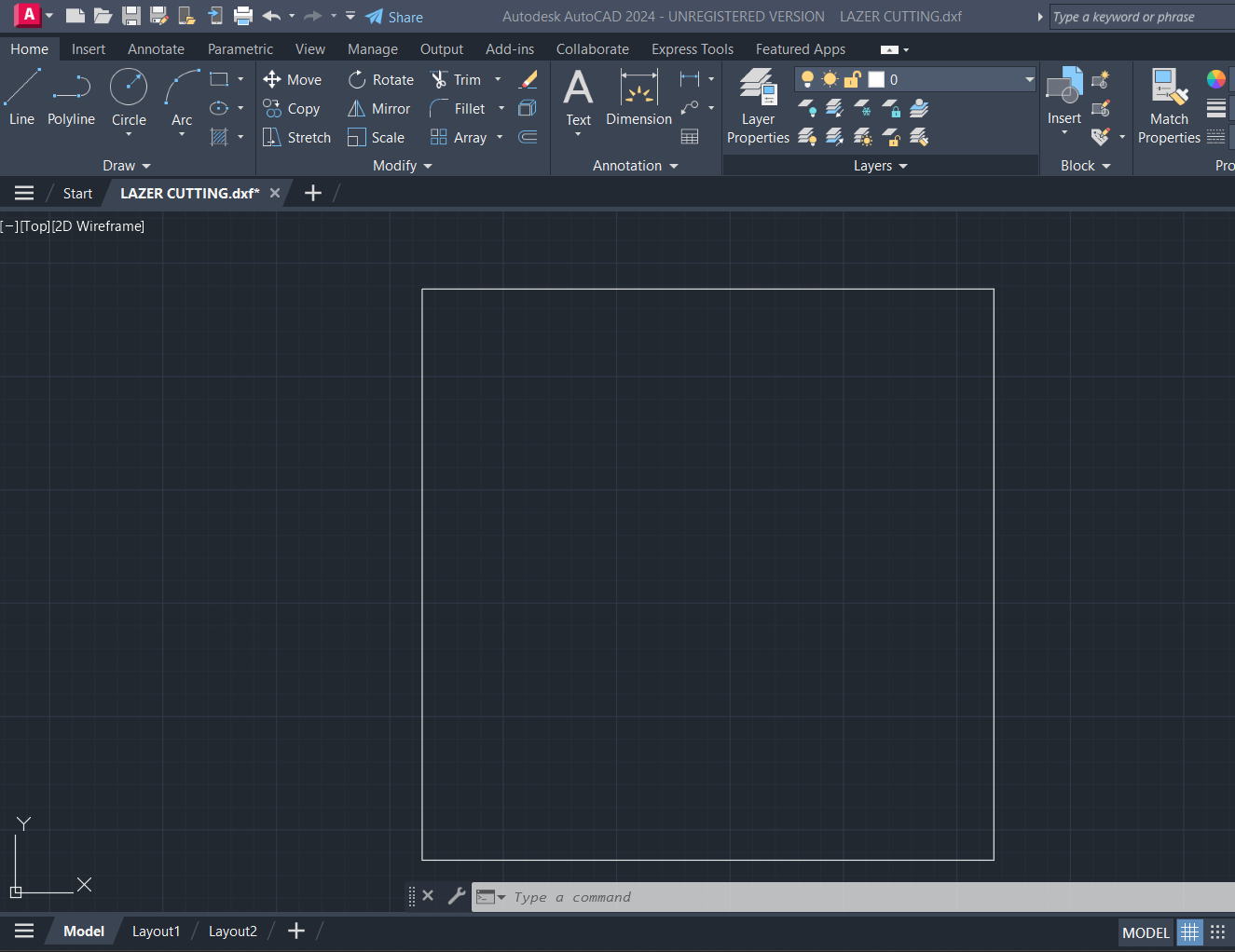
I started my desin with square design of 63mm x 63mm.

I sketched where I wanted to pocket.
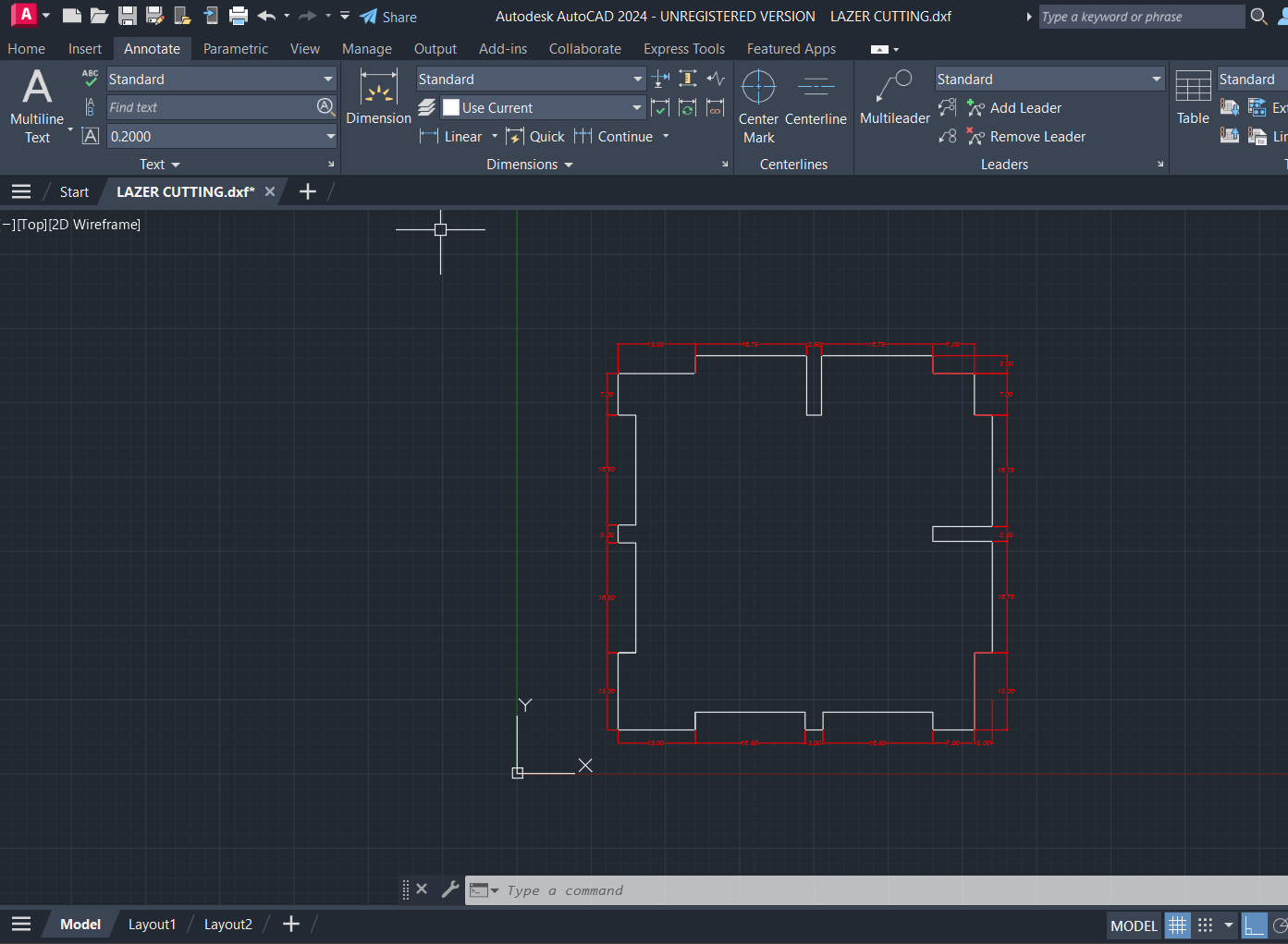
This is the design with all dimensions and then saved as DXF file to be used in printing.
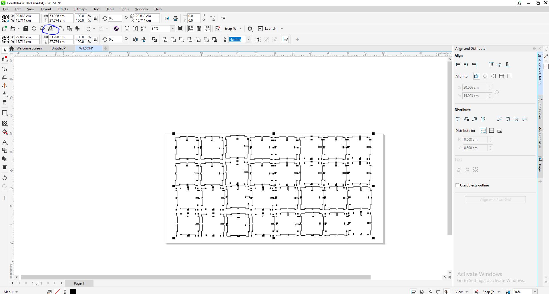
For printing my design I imported the design I made into corelDraw software, and I duplicated my design to print many parts.
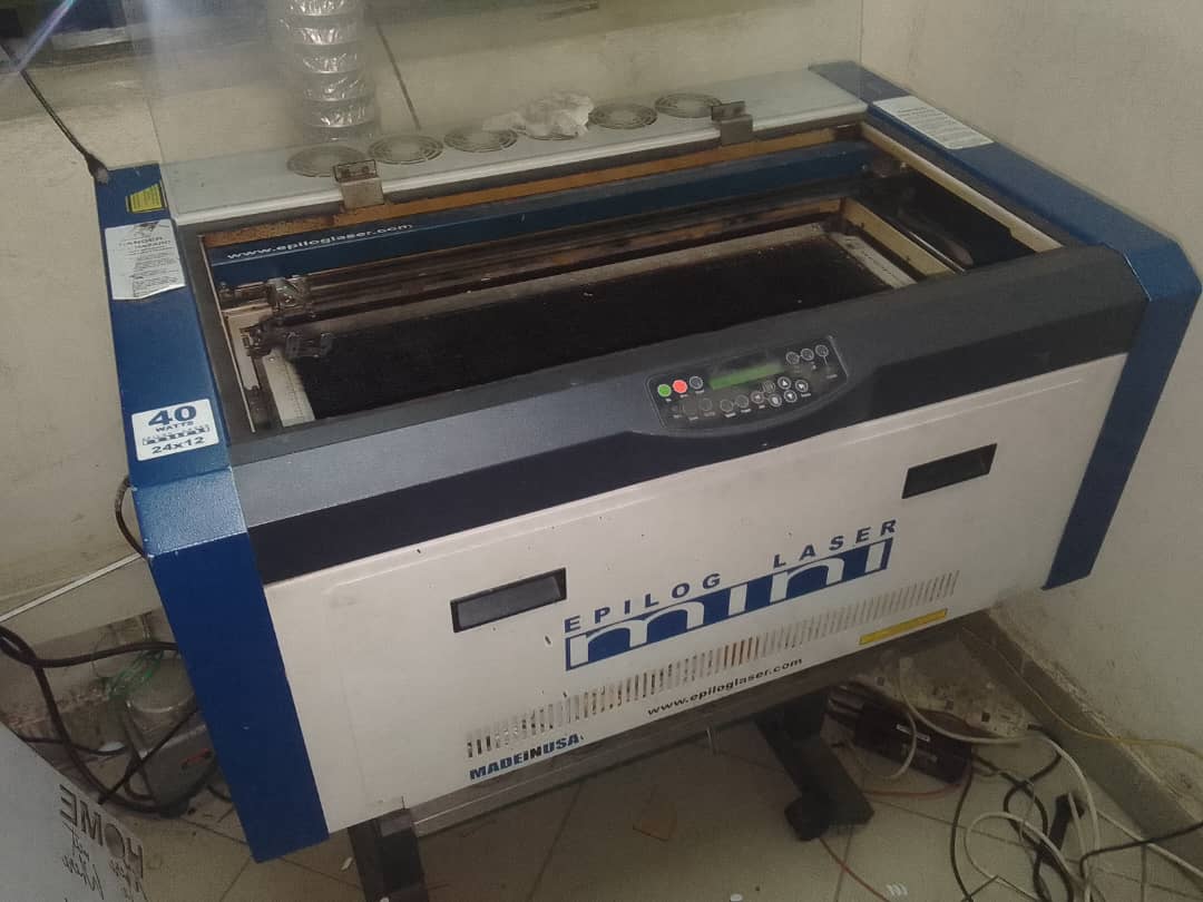
Lazercutter machine in our lab (Epilog Lazer)
Selecting parts and do printing
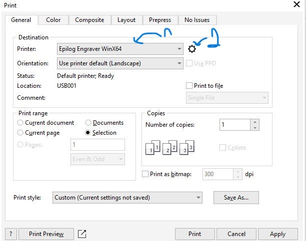
Making sure the printer is turnedOn, Select the our printer and click setting
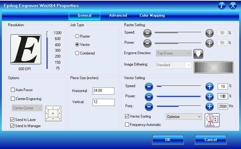
Setting paramters of the printer for cutting parts
For the laser cutter Epilog Engraver Winx64, we used the following parameters for cutting the 2.5mm MDF sheet:
- Focus: Adjusted manually using a pointer, ensuring the laser beam is optimally focused on the material surface.
- Power: 100%
- Speed: 10%
- Frequency: 2500 Hz
- Kerf: 0.2mm
- Joint Clearance: Adjusted for a tight fit
Through our experiments and adjustments, we found these parameters to be optimal for our specific material and design requirements, ensuring high-quality laser cutting results.
After cutting all parts I made in laser, assembled them to create something with them.
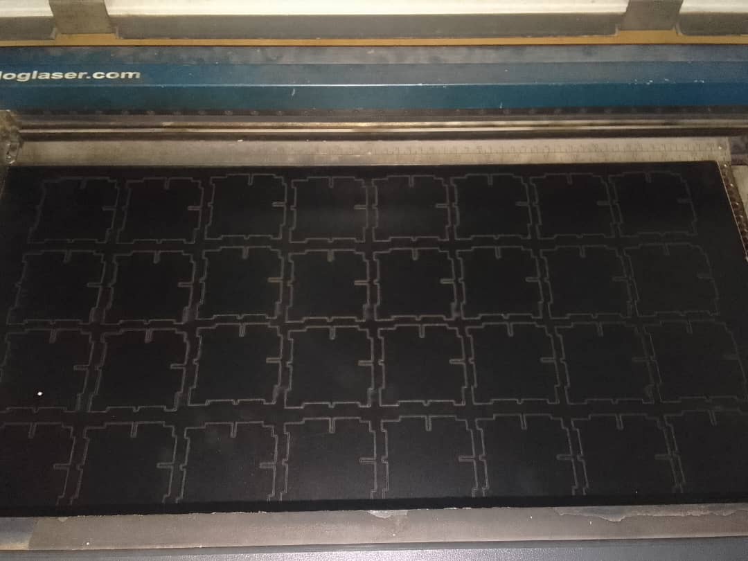
Parts Cut
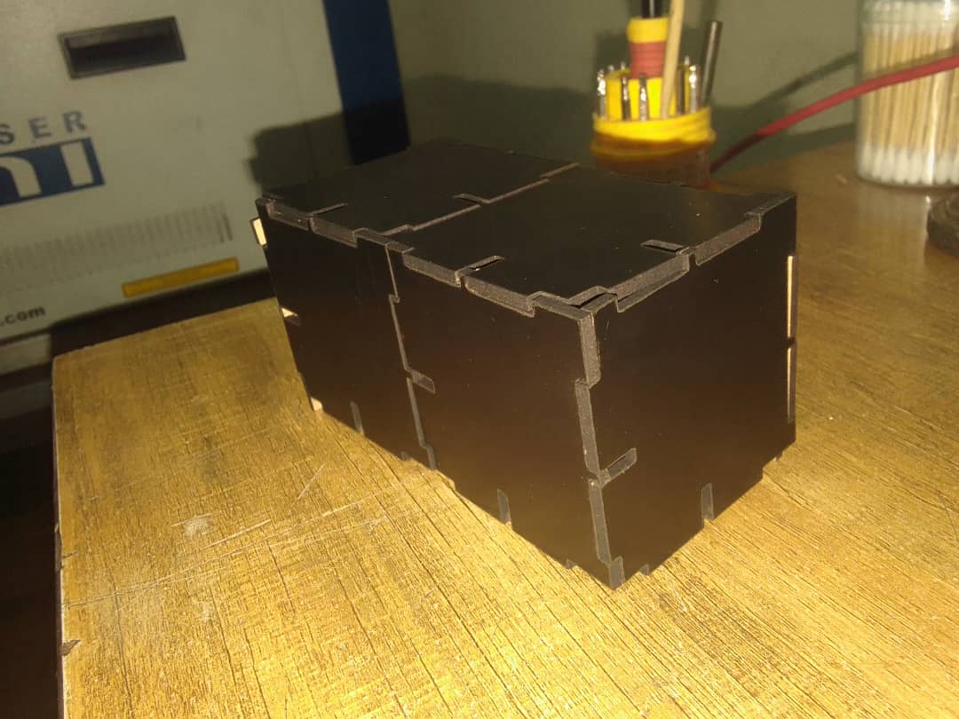
Assembling parts into a box
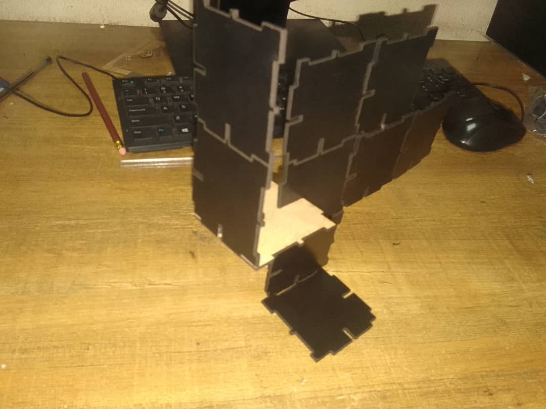
Assembling parts into fineshape
Group Assignment;
- do your lab’s safety training
- characterize your lasercutter’s focus, power, speed, rate,kerf, joint clearance and types
Group Work Reflection;
Our group work assignment, we were tasked with characterizing our laser cutter’s focus, power, speed, rate, kerf and joint clearance. We worked togehter to test the project and Wilson helped the team on documentation of the work done.
I have added the link to the group assignment page. Here is the link: Group Assignment Page.