Week 7
Computer Controlled MAchining
Group Assignment
The group assignment link can be found here
In this week group assignment i was to document what i have learned from using the CNC shopbot which is to first foremost learn safety rules because it's the most important either for your self and the machine. Secondly i learned that the output of the machine becomes different depending on how you set the toolpath, what part of the material you need from the piece thats been cut whether if its the cutout or the inside part. THe feeds and speeds depend on the on what kind of material you use and how thick it is. Aligning files on the workspace is done using a feature in the commands called Move Selection, feeds is set depending on the type of material we using; so we have the plunge rate is set between 0.6inches/sec-1.2Inches/sec while the feedrate is set between 0.8inches/sec-1.8inches/sec whereas speed is set to 16000rpm and is affected by the tool diameter and it is also affected by the stepover the lower this stepover the longer it takes for the work to fininsh. We set ours to 65%. We worked with MDF materail but i'm also familiar with acrylic. As for the number of passes while calculating the toolpath,it is set according to the type of material, the tool diameter, the feeds and speed.
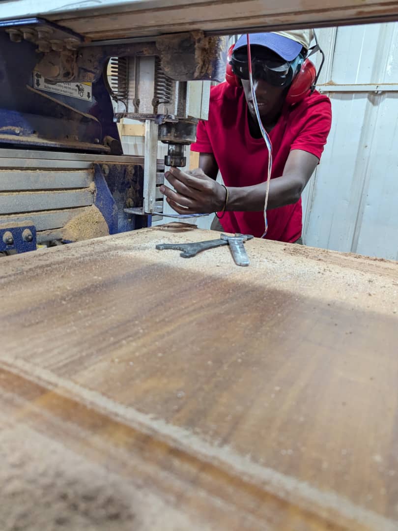
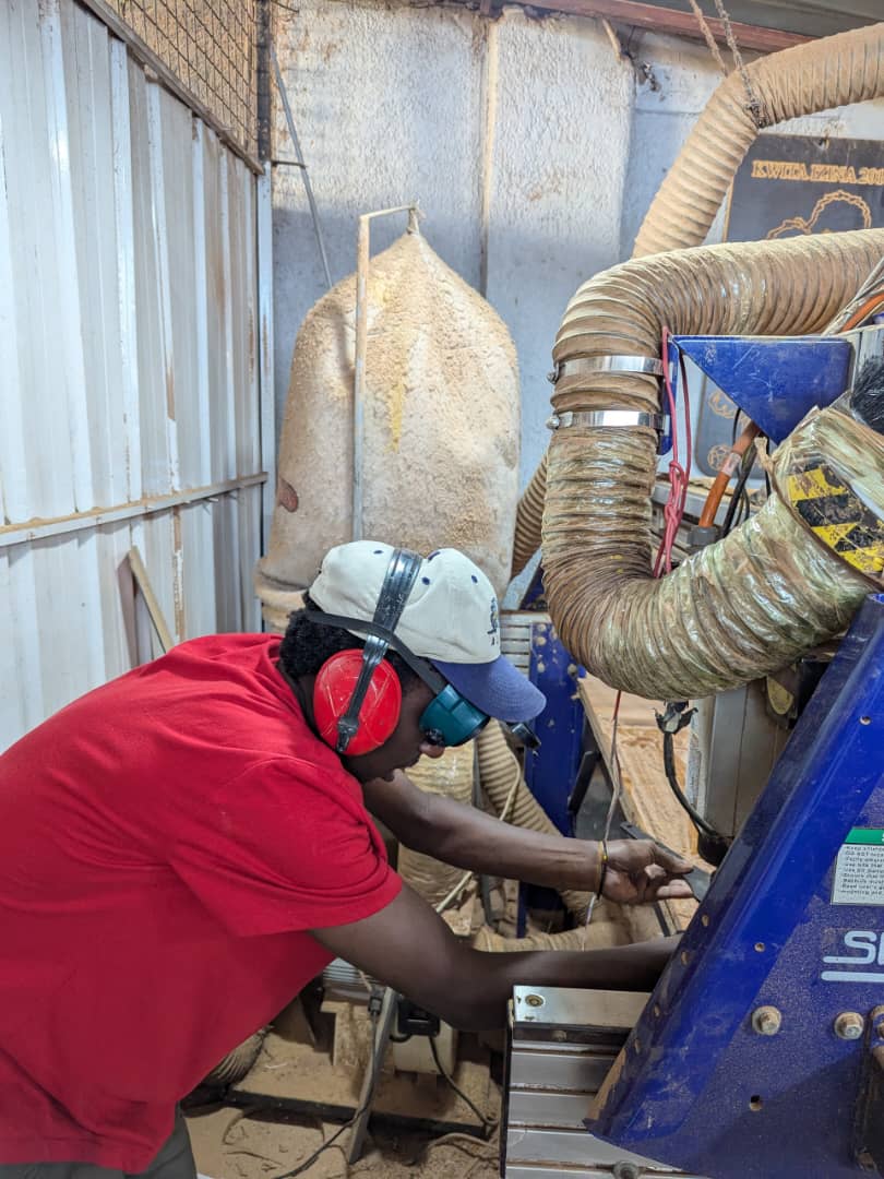
For whats regarding safety i used ears & eyes protection i wore glasses to protect myself from small dust particles and noise reduction for ears then also its important to wear xlosed shoes and for long hairs, you should find a way to tuck them into a hat or a helmet
This week's assignment was centered around making something big so i choose to make a cabinet/shelf so i started off by sketching the model on a paper
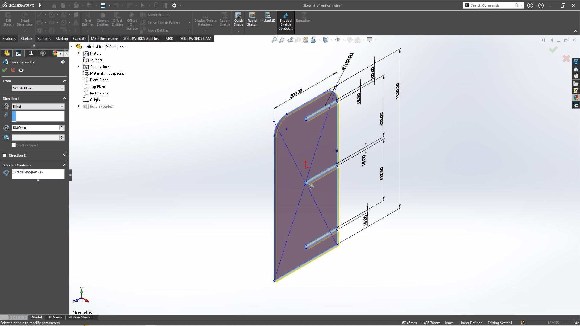
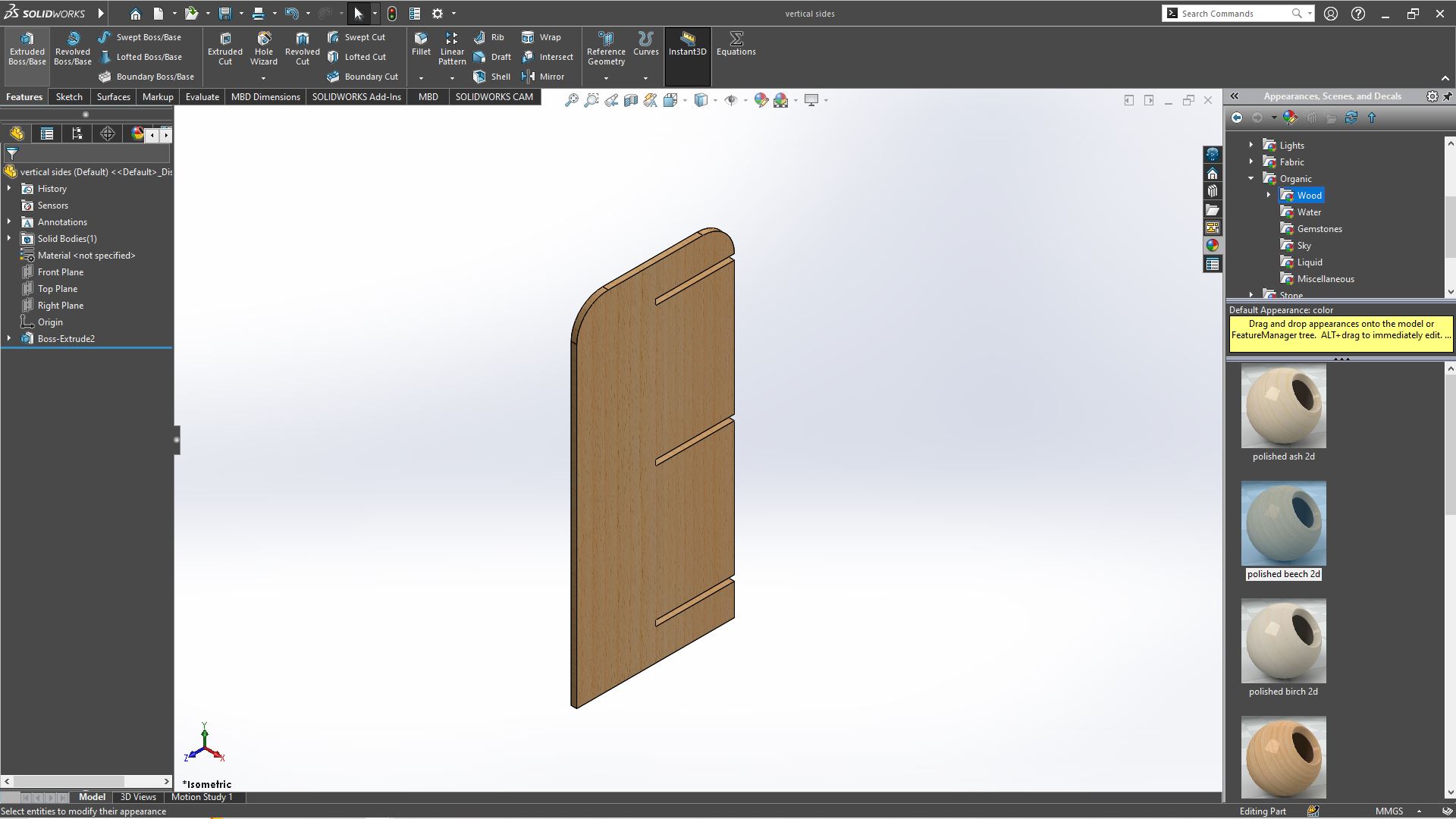
I proceeded with starting the design using the 3CAD software SOLIDWORKSand the reason why i choose this CAD is because it can help assemble the design and have a clear view of what the final model will look like but also i'm also familiar with the software due to using it beforehand on multiple occasions. the model is made up of two parts that had to be designed one for the vertical parts
.JPG)
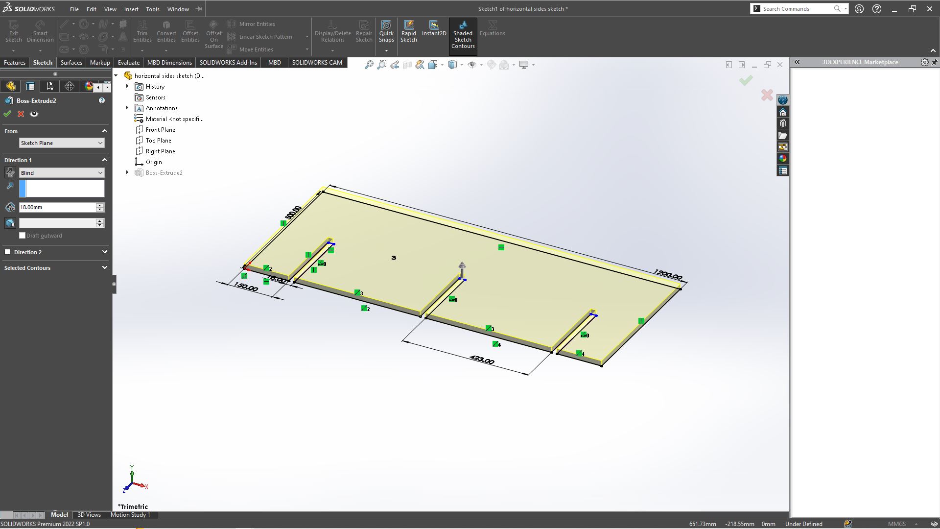
Another sketch for the horizontal parts.
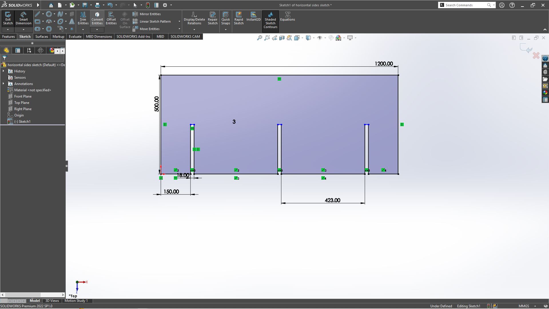
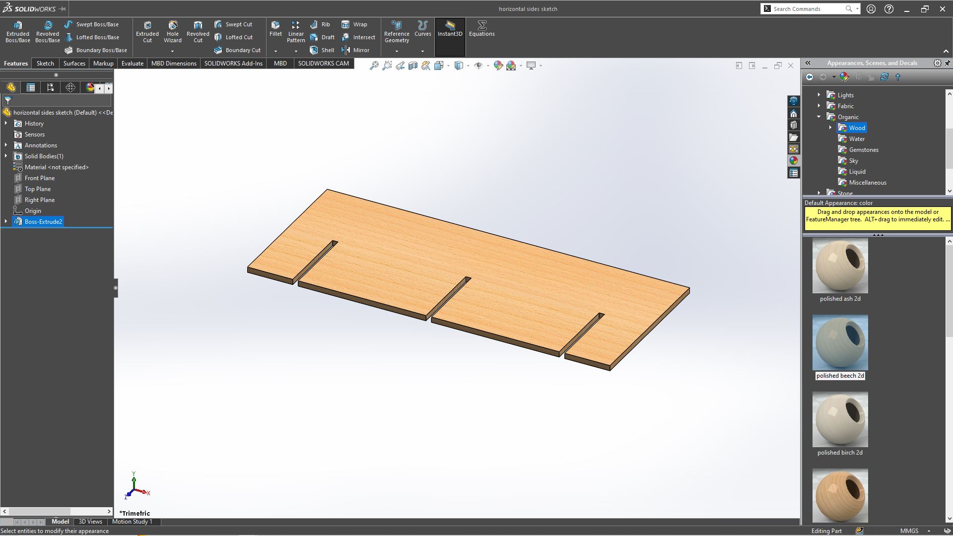
After sketching there's a feature for extruding the sketch to the thickness of the material, i used the 18MM thickness MDF so due to this fact i extruded these parts to 18MM thickness and after the model has to be saved in order to be accessible in the assembly side of the model. hence it was saved under the Horizontal side sketch while the other part was saved under vertical sides, to the right side of the workspace
- Extruding vertical parts
- Extruding horizontal parts
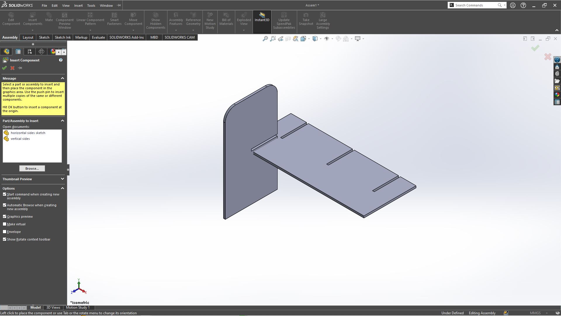
Assembly
After extruding both parts you save each part, then moved on to assemble the desired cabinet/shelf. There's a feature that can be found in the toolbar for assembling, named NEW you click on its drop down menu, scrolled down to Make Assembly from part/Assemblythen it opens the features that can be seen below in the picture. So at first it opened with the horizontal part i just finished extruding. BUT if you have open Solidworks aside and then opened Assembly the features to inserting componnents can be found above in the commands manager then insert components then a panel opens on the left side, you click on browse to search for the files to be assembled. after its selected you move the curser to the workspace and click to deposit the side and then selected the other part, moved the cursor to the workspace to click and drop the other part.
After putting them in the workspace, i opened mate feature under Assembly in the commands manager.
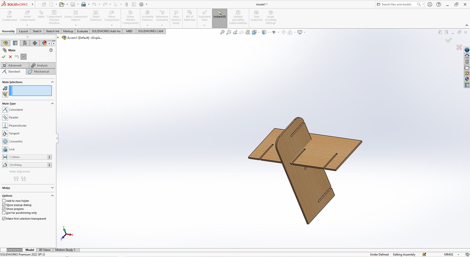
To assemble parts, there's a few ways to go about it you can mate two surfaces, by selecting 2 faces and mating them, mating two edges or vertex, so after you have selected both vertex, a menu pop up requesting to choose, between Coincindent , Parallel , Perpendicular , Tangent , Concentric so i chose coincindent but bare in mind that it can be tricky because due to the methods you use it can take multiple steps before you mate correctly, so i used vertexes as it only uses one step to mate and for mates. Due to the Solidworks year version mine is 2022, there are 4 types of mate depending on the types of model you want to assemble, i used the Standard due to the fact it wasn't a more sophisticated mate but there's also this Advanced , Analysis and Mechanical. So when you add
- Selecting the first vertex
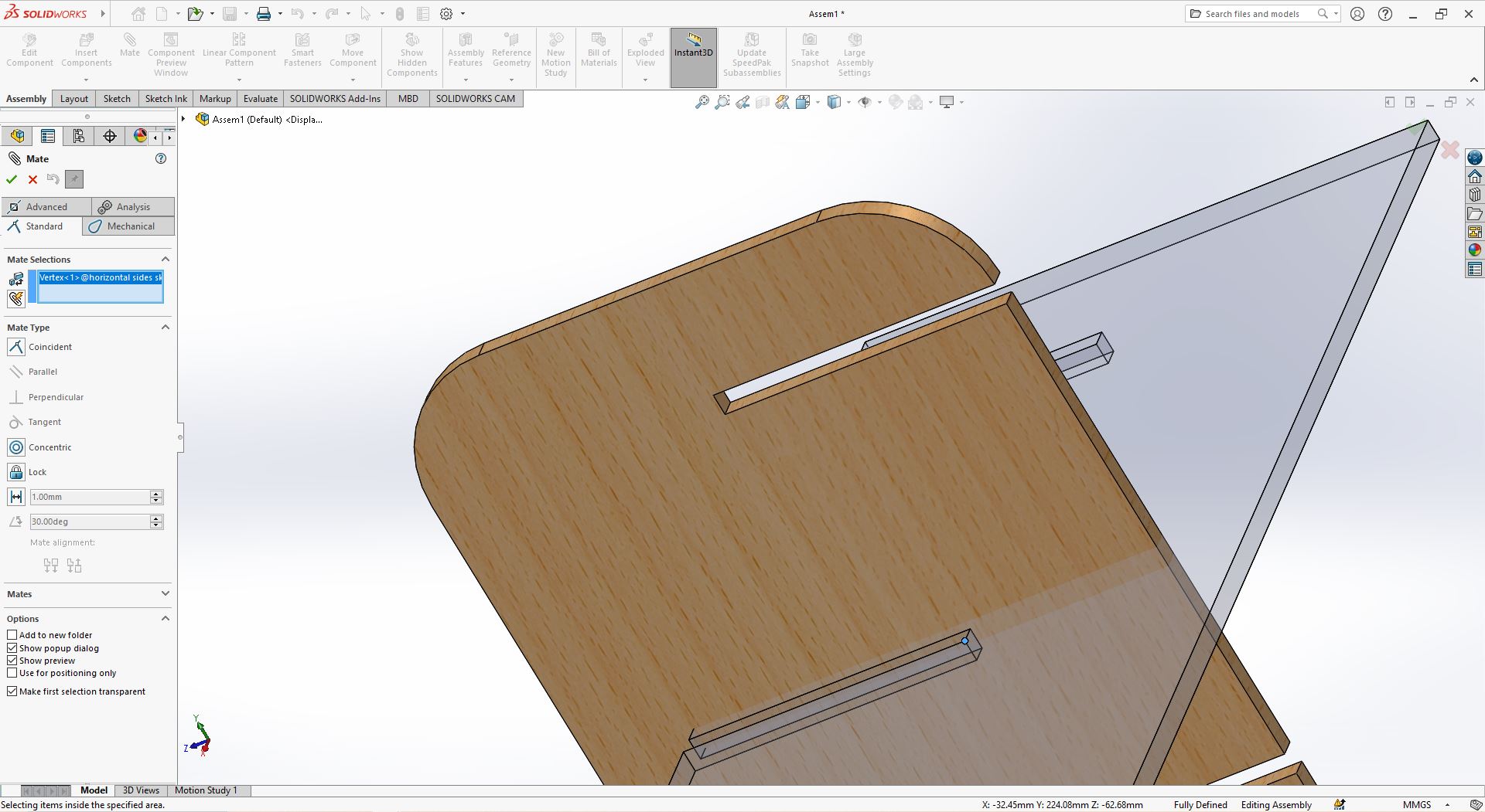
- Selecting the second vertex

- Final mate
So after getting vertex together i clicked OK to apply the mating.
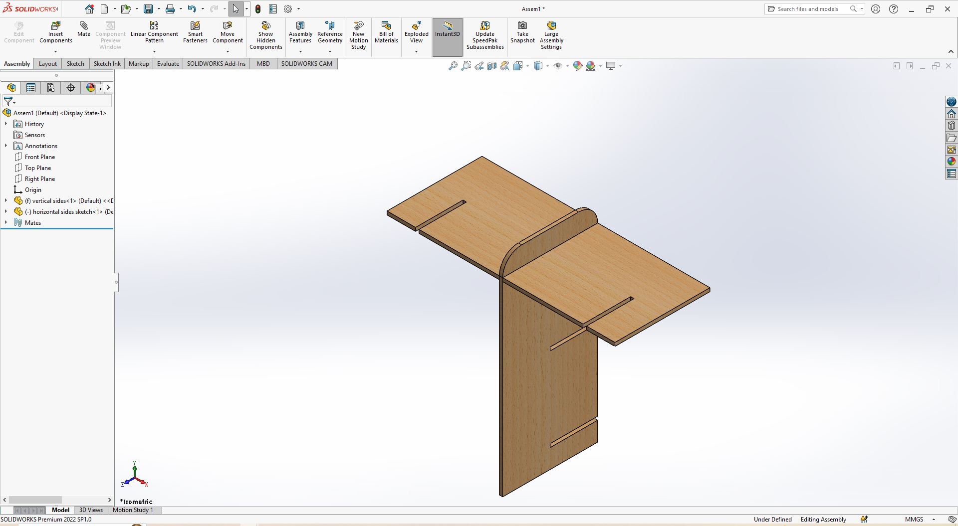
- Added all the horizontal sides.
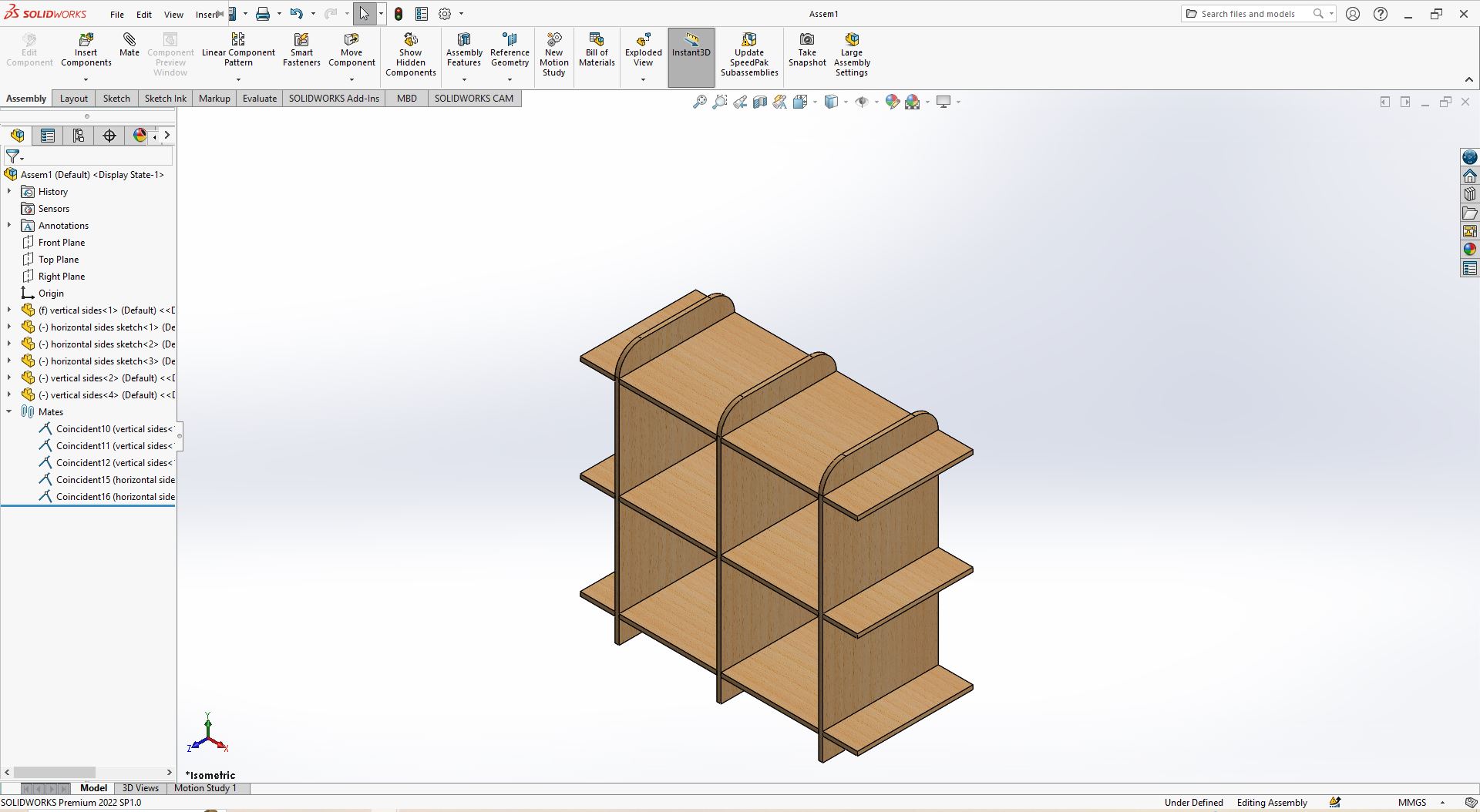
Added the two remaining horizontal sides and then moved to Coincindently add vertex together one by one.
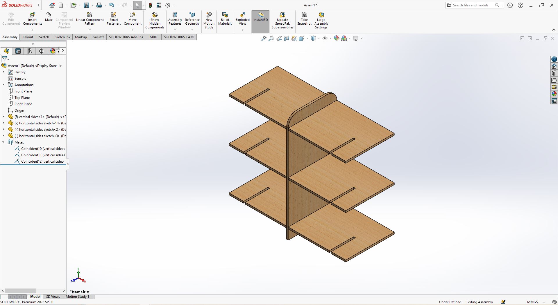
Added the two remaining vertical sides and then moved to Coincindently add vertex together one by one.
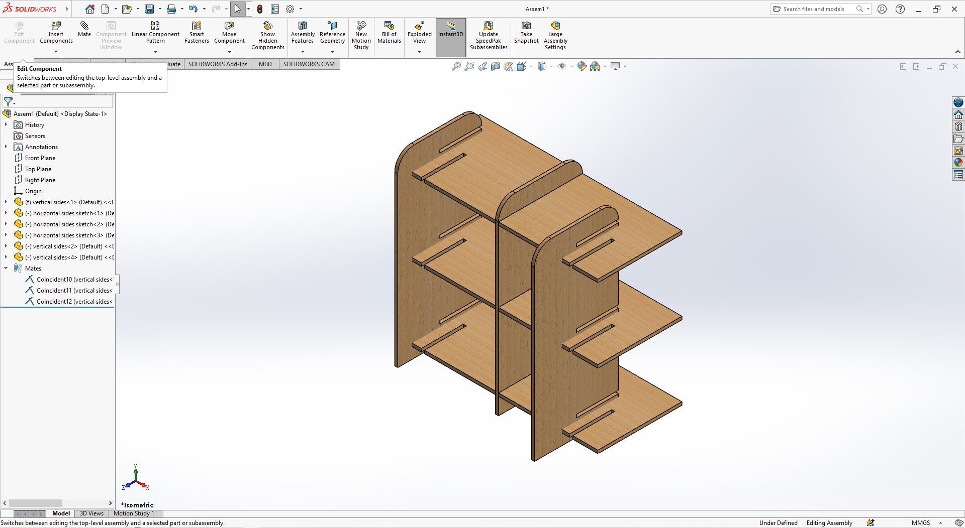
The Final model
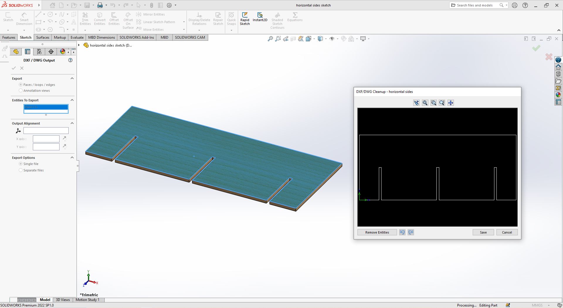
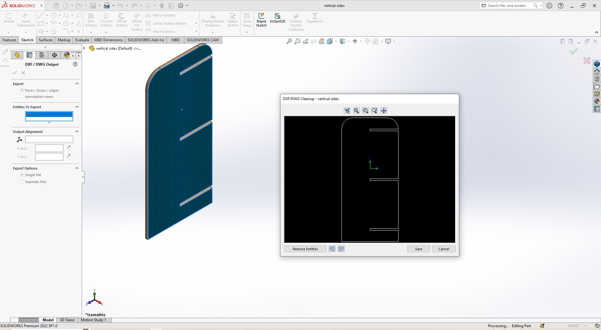
After Saving the files, I also saved the parts as DXF type file but in a way that we save one face of the model as vector file, here's how i did it you go to save the file as usual then save it as DXF type file, it brings you back to solidworks then there's a panel that opens up titled DXF:DWG Output on the left side of the workspace, then select Faces/loops/edges click on the face of the model you want saved as a vector file then preview window opens up to show what would be saved as a vector file then click on SAVE then the file will be saved as vectorized DXF file.
- How i saved horizontal dxf file
- How i saved vertical dxf file
Machinining.
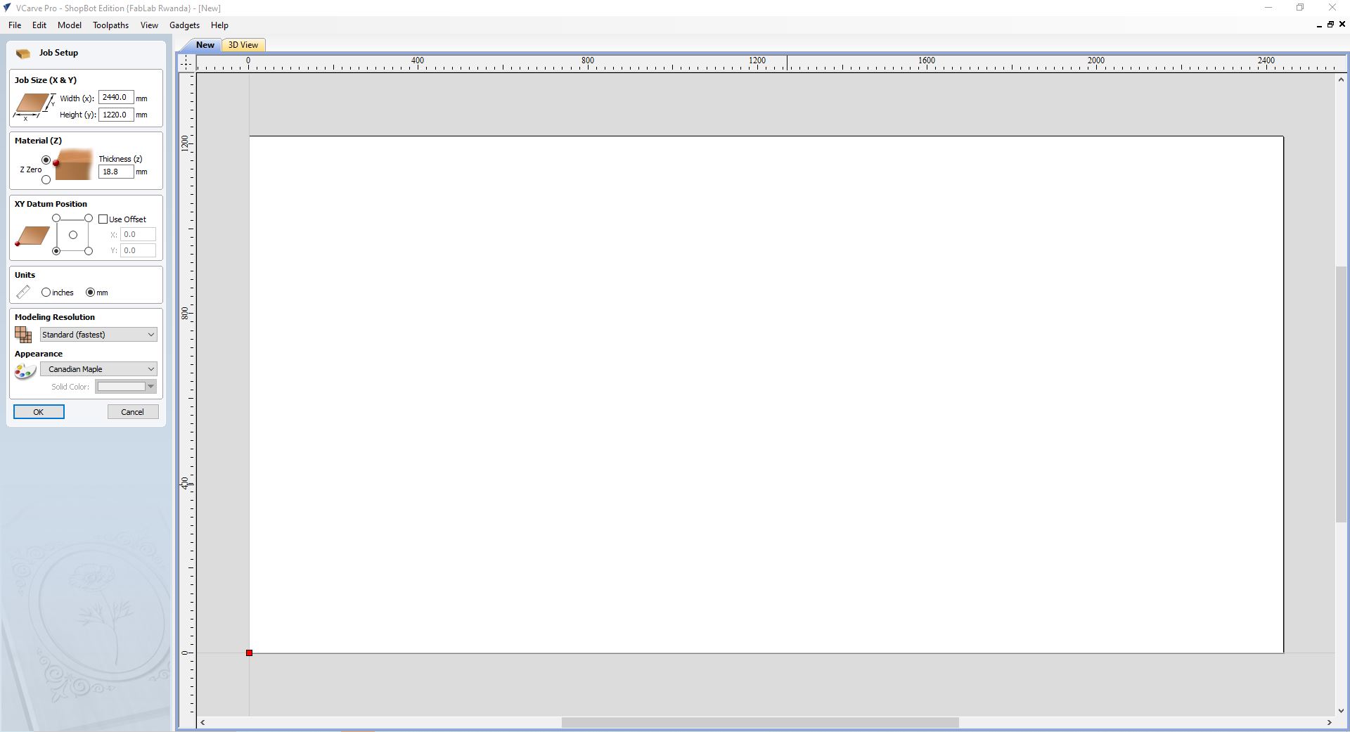
For the machining part i used the DXF files saved from the solidworks model in the Vcarve software. The Vcarve is a software for creating and cutting parts on a CNC Router and our CNC router is shopbot for which further info can be found here, so first you set up the size of the workspace/sheet size, the type of material and it's thickness 18MM and the surface at which the tool will start cutting or the top layer of the sheet/at Z axis 0, next is the working Unit these are the basics of my job set up, but there are other settings for material type, design scale but i wasn't going to use it which is why i left it
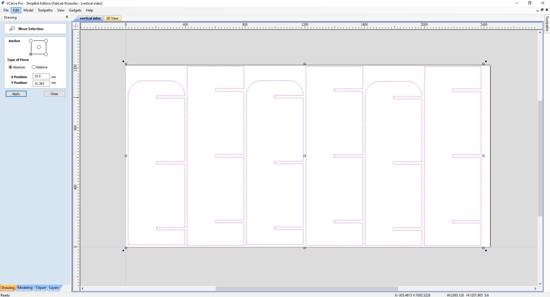
I imported the DXF files to the vcarve then selected all the vectors, to multiply it you can either Hold control drag the mouse and then release it Or copy and paste to the side after that i aligned the vectors to the workspace using a feature in the commands manager under Transforming Objects there's a feature named move selected this helped me to align the vectors perfectly to the workspace by leaving a clearance gap of 15MM to the X axis and 10~11MM to the Y axis for clamps to hold down the sheet tot the machine bed
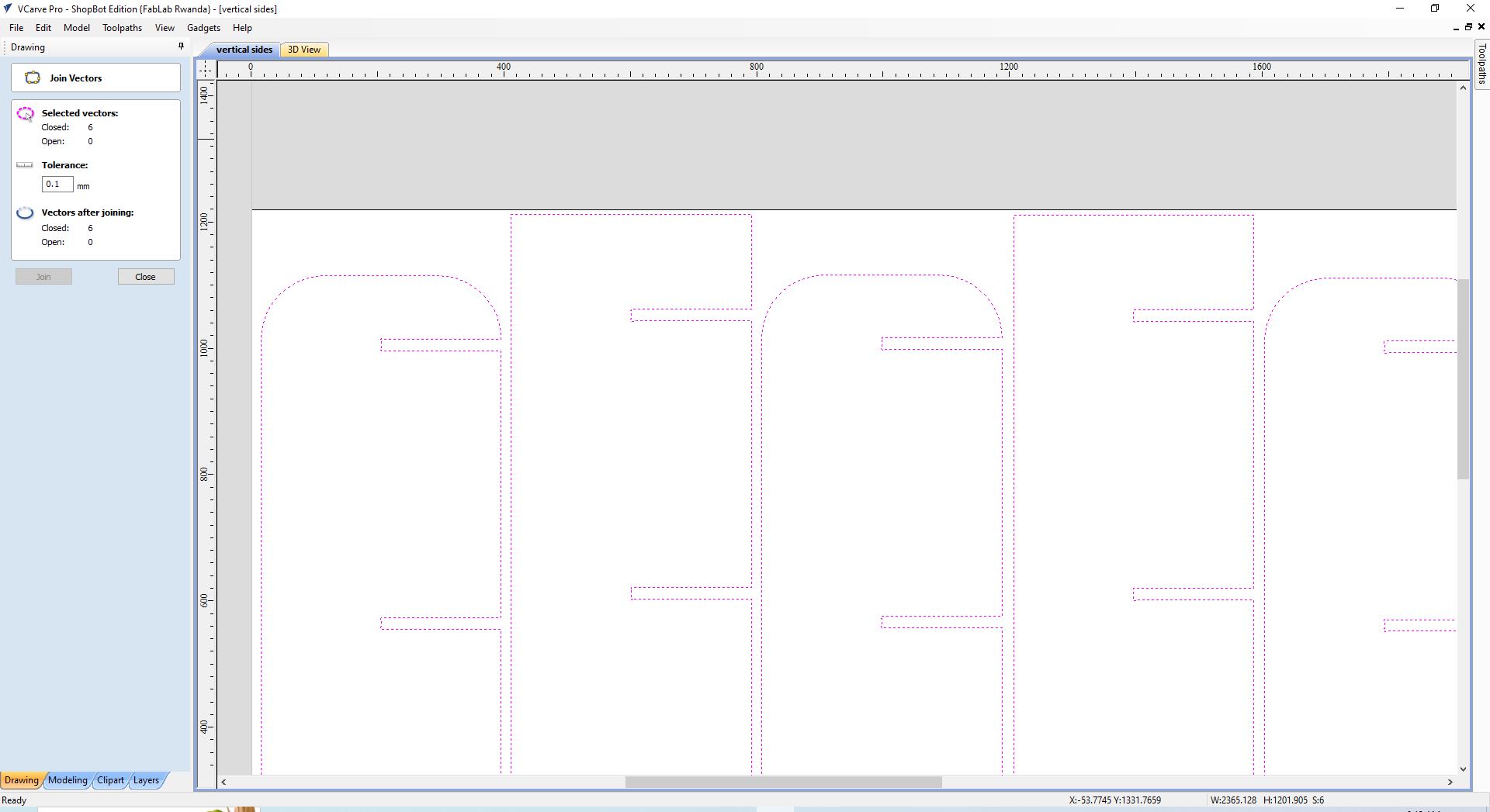
Due to some of the vectors not being fully closed, this is at times due to vectors produced or being generated by another software in this case solidworks, there's a feature in the drawing panel of Vcarve under Edit objects the second icon on the fourth line is for joining open vectors so i selected everything then clicked on join open vectors, with it's opened window i set the tolerance gap to be 0.1MM then clicked on join, then close to apply the feature. As you can see there was 6 open vectors that closed
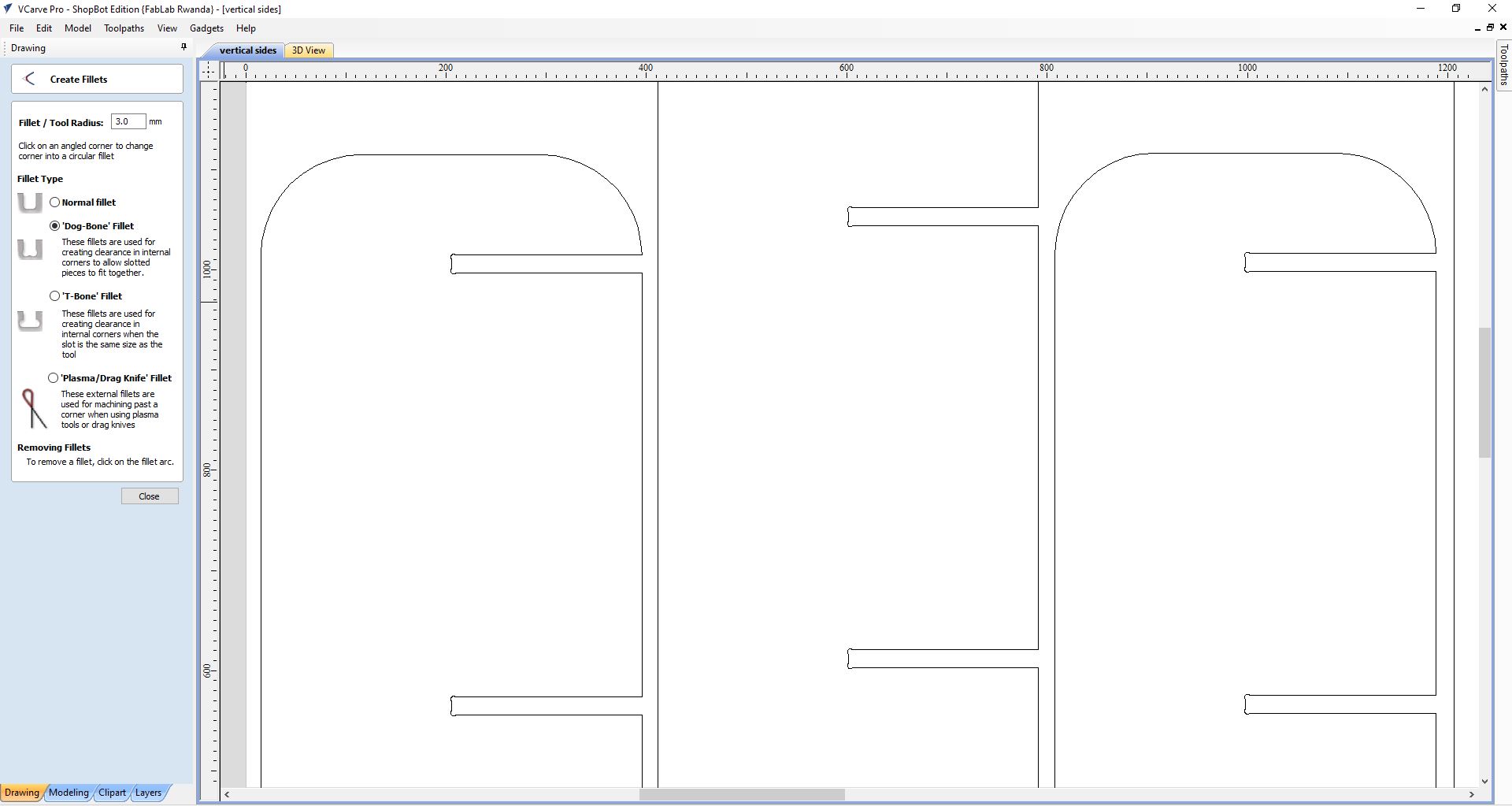
Now for the pieces of MDF to be machined, we add Dog bone a feature under fillet, and fillet is located under edit objects in the third line of icons,first icon, i set the tool/fillet radius to 3MM, this is done due tot the endmill tool being round so the corners are also going to be round so if we add the pieces together it's not gonna fit to the end due to inside round corners so we add dog bone for tool to go inside past corners round so that when we fit the parts together it holds perfectly
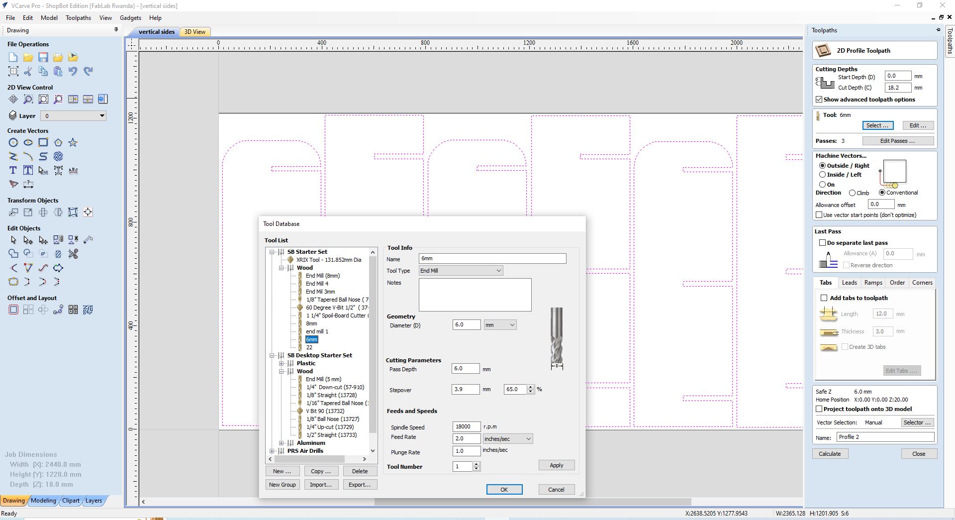
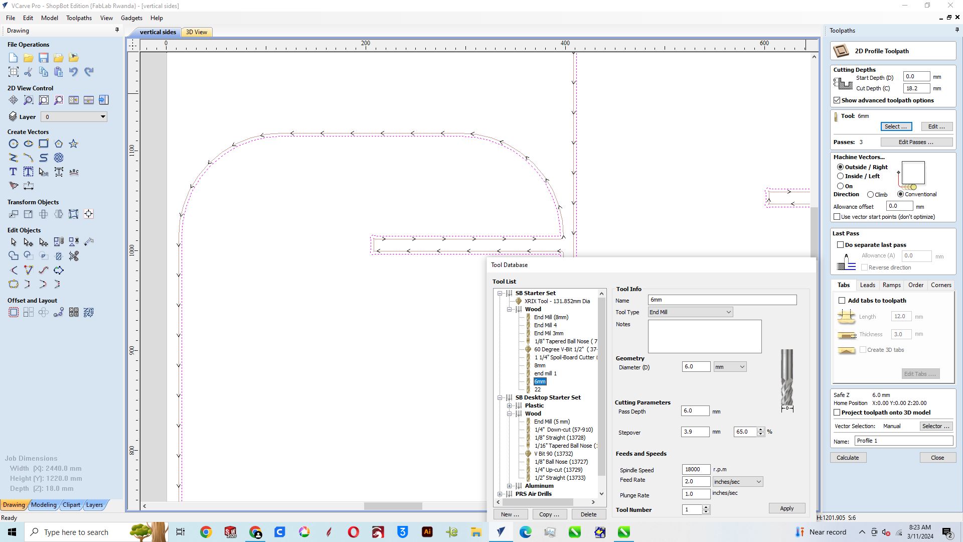
Cutting Parameters
For cutting parameters in the toolpaths panel i clicked on the 2D profile toolpath, set the start depth to O MM and the cut depth to 18.2MM usually it supposed to be the same thickness as the MDF material but we add the 0.2 MM in order for the tool to go past the MDF sheet help cut out the pieces completely. the tool Diameter is 6MM, the stepover i set it to 65%, this is means that in between the lines of the toolpath, the distance will be 65% of 6MM, the speed of the spindle to be 18000rpm, the feed(the speed at which the tool travel horizontally) set to 1.8INCHES/SEC, the plunge rate speed at which the tool travels vertically; meaning how fast it pierces the sheet of material, i set it to 1.2 INCHES/SEC, clicked apply and close, passes set to 3 due to the fact, a single pass shouldn't plunge to a height beyond the diameter of the tool meaning 6MM so i set three passes, for machine vectors i choose Outside due to the fact that i wanted the cutout pieces and then i clicked on calculate to see the time it would take to machine this which was about 1 hour 25min
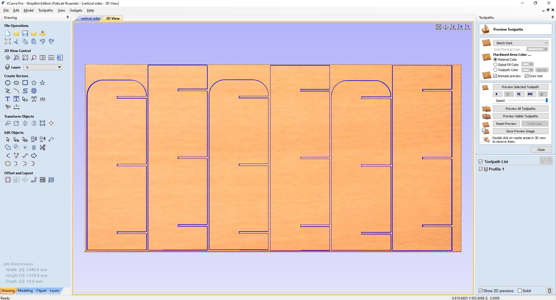
After calculating
Previewing
Saving Toolpath
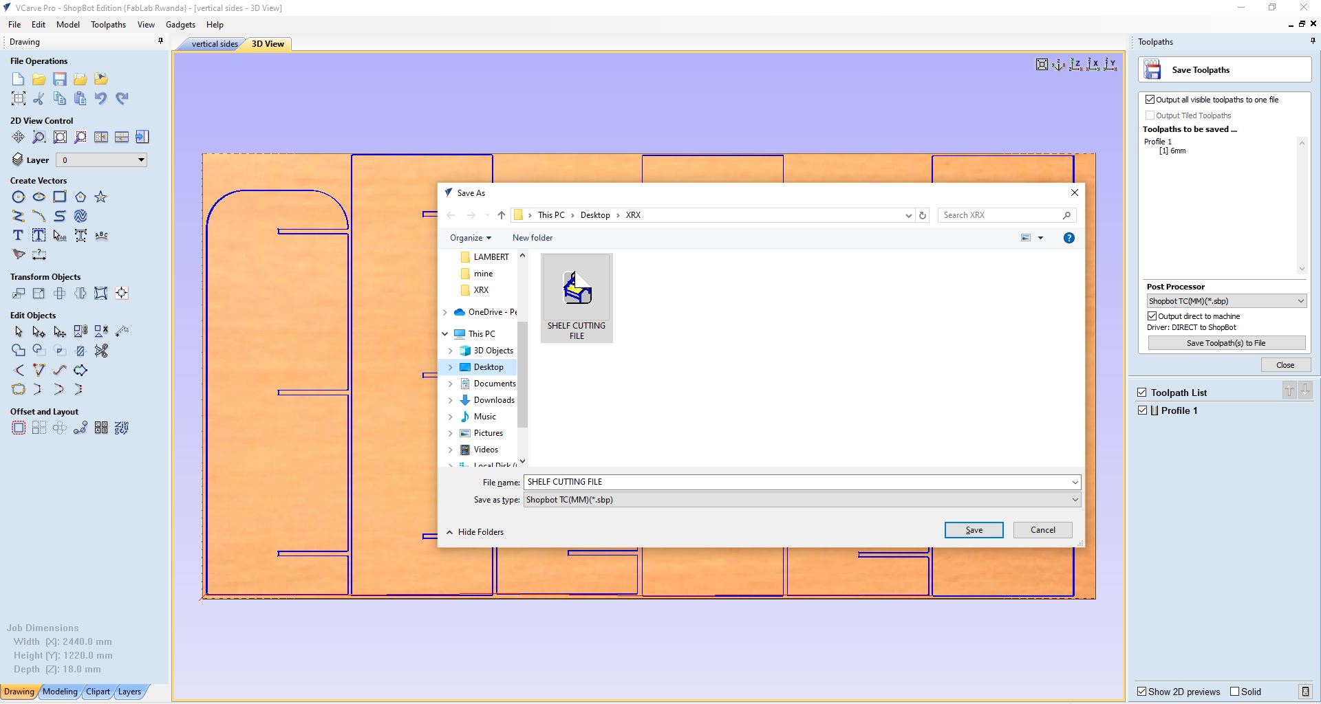
Setting axis
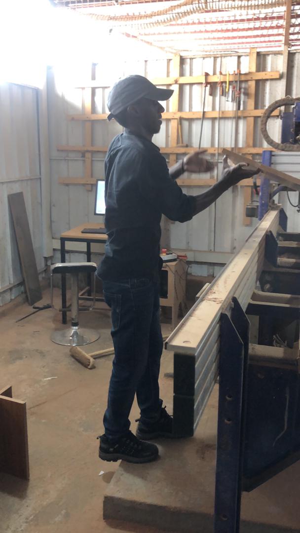
So after you have saved the file, it automatically opens up the shopbot controller and using the controller to set the origin. I turned the CNC router switch on, locked the machine to the computer with the reset button(the blue button on the pushbutton) in order to be able to drive the gantry using the controller handles. After, i moved to positioning the tool at the origin of the sheet material as precise as possible, to set XYZ or the beginning of the machining
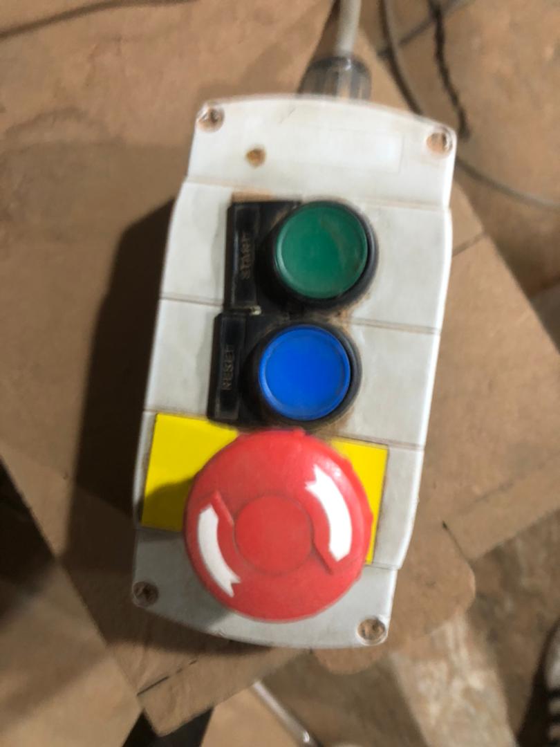
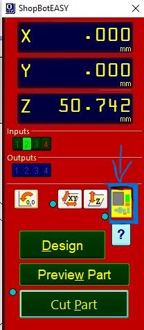
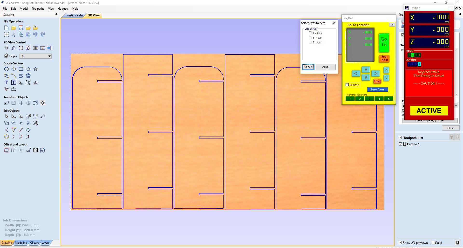
Setting zero axis on the controller on the controller panel, there is a small yellow keypad, i clicked on it opened another panel now you click on the zero axis then it opens another panel for selecting the axis i'm going to set at zero hence the origin of the work so i selected all 3 axis; XYZ then clicked on Zero then i closed the yellowpad
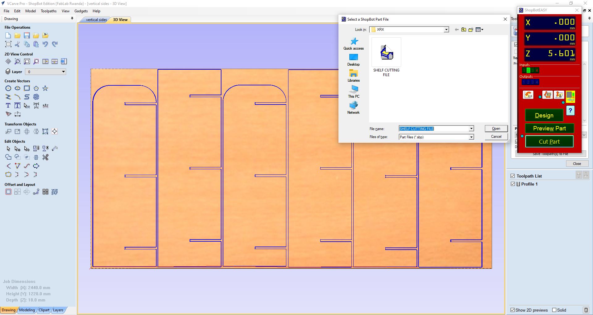
After setting XYZ i moved to start machining so i clicked on Cut part then it opened where i had saved my file before then i clicked on Open
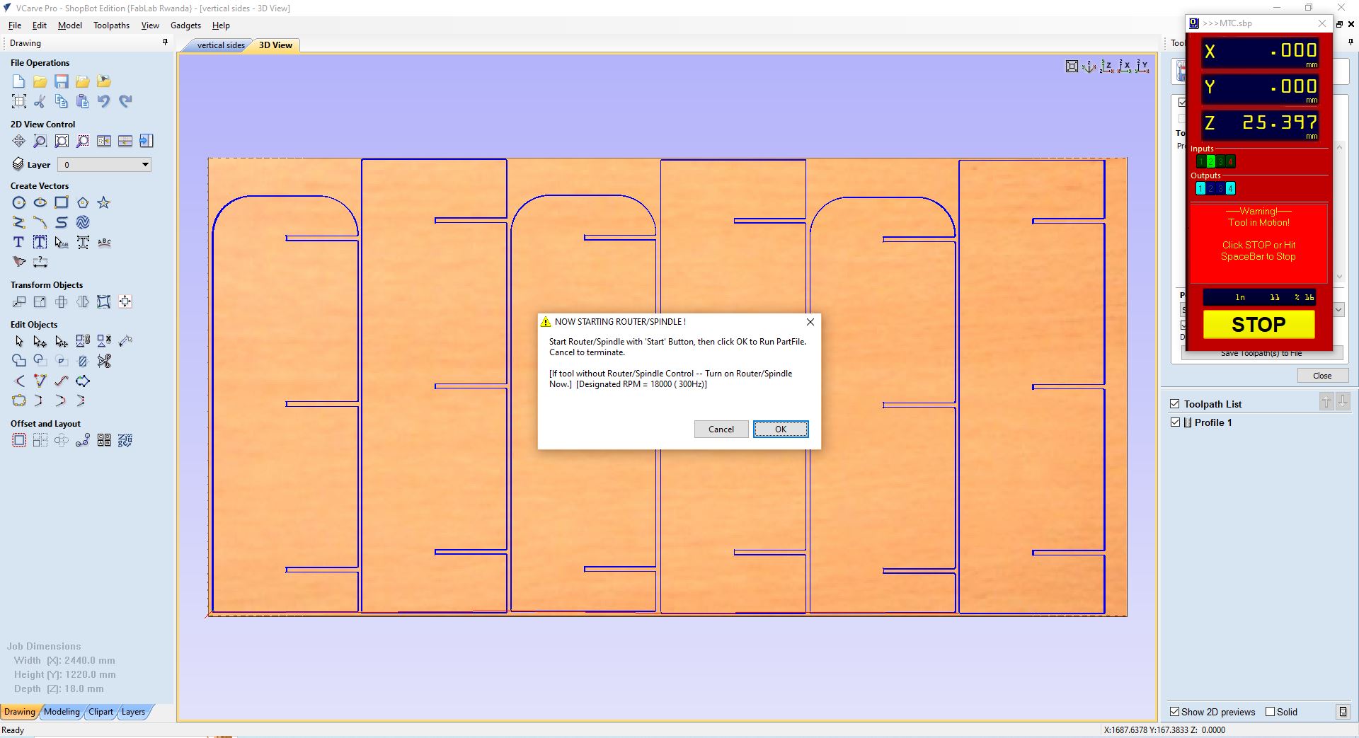
After clicking on open before you go on with starting the work you must turn on the spindle first to avoid tool damage, i pushed the start button (the green button on the push button) on the pushbutton box to start the machine spindle and then with the window that opened on the screen i clicked enter on the keyboard and the machining started
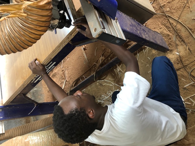
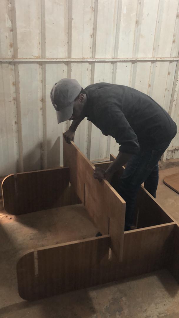
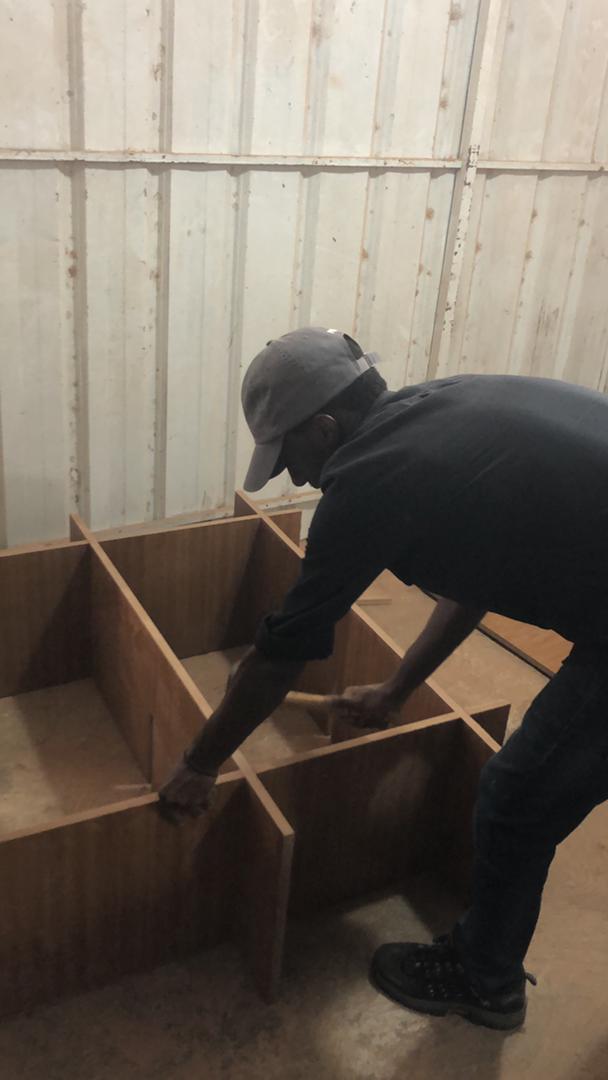
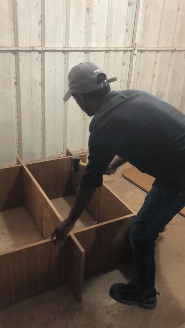
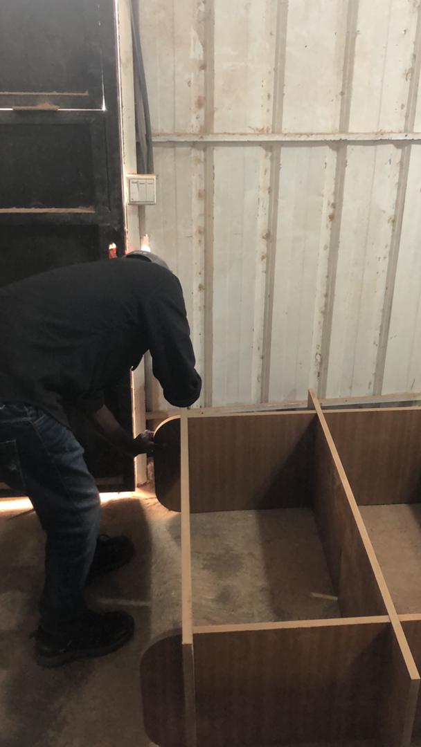
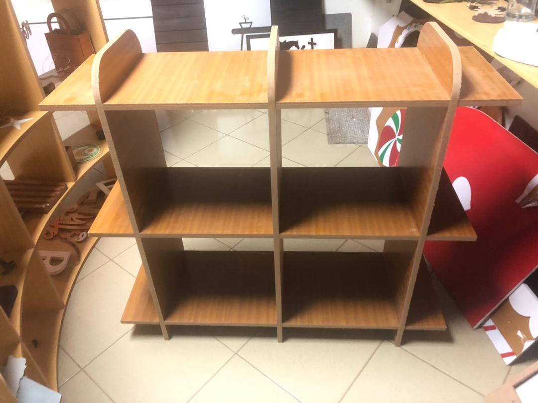
After Machining, i assembled the parts to make the cabinet/shelf uisng the mallet to punch together the parts that hardly fit together.
Assignment Files