Week 2
Computer-Aided design
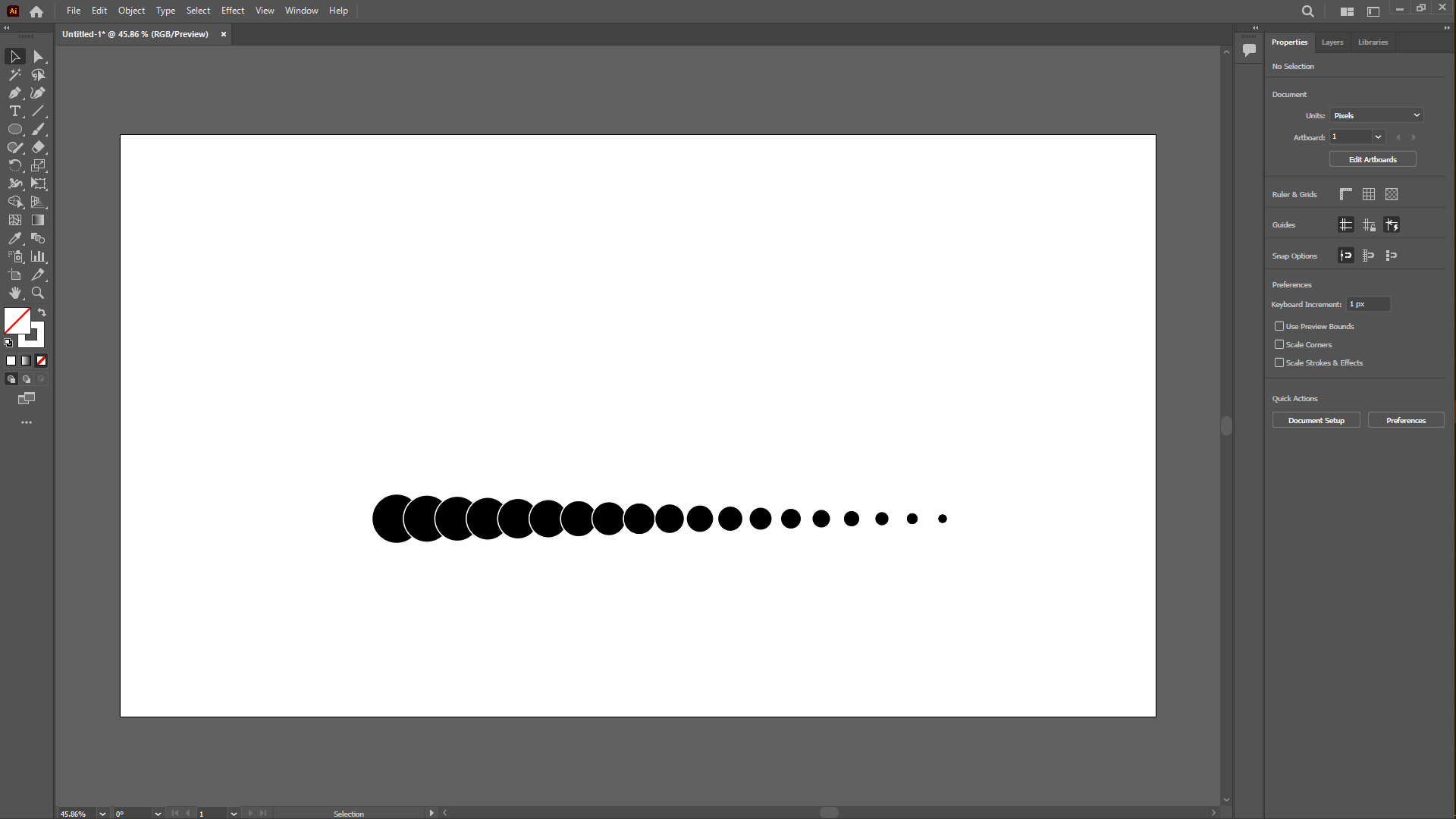
For this second week i able to design the 2D part on my end i used a vector based software; illustrator. So below are the design that was able to make using this software. First i opened illustrator then i then i drew a circle copied to its left another circle, selected both then i used a feature in the toolbar under object, then click on blend then click on make
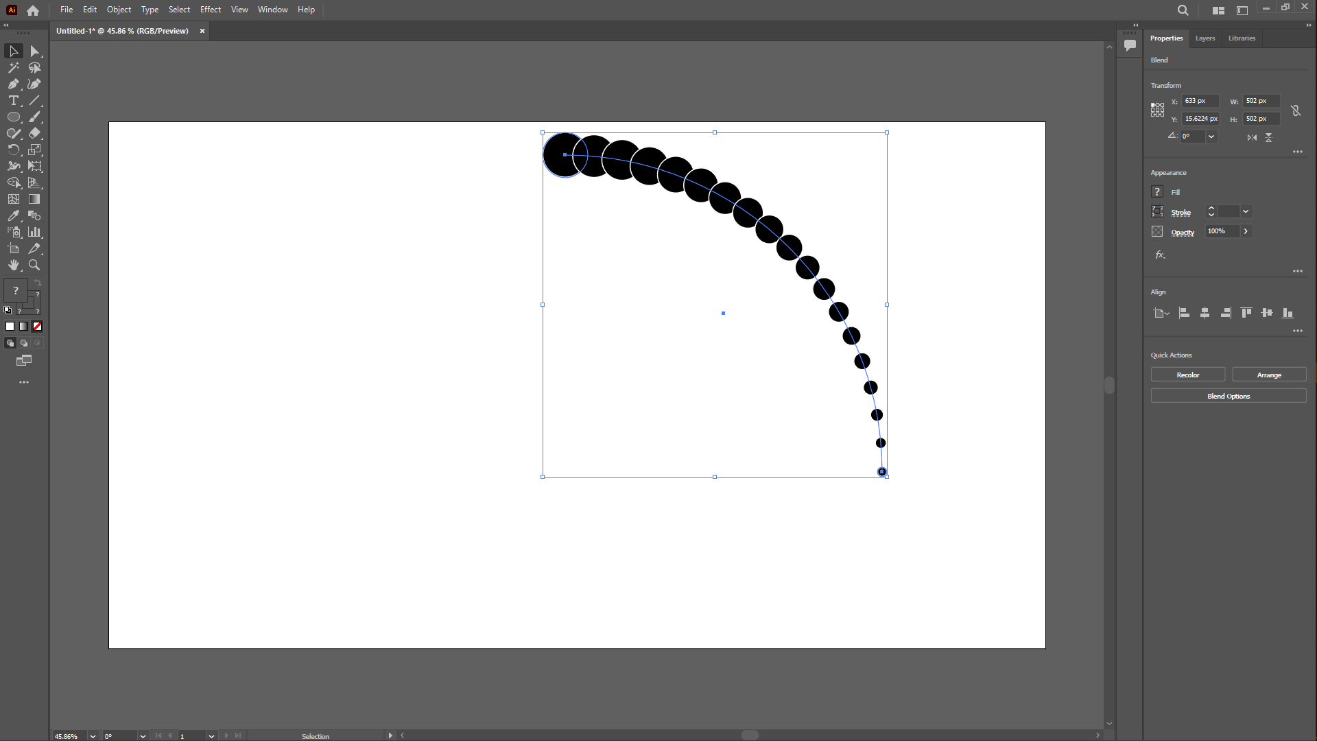
i then drew a circle then selected its 3/4, deleted them then selected everything clicked on object again then blend, then replace spine
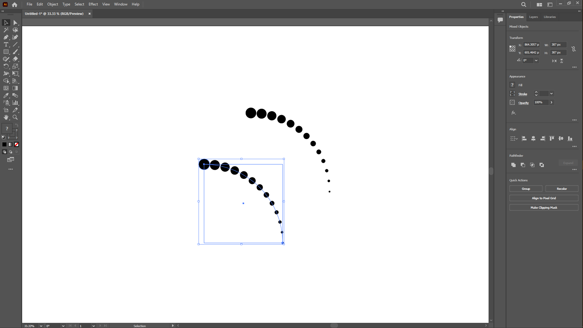
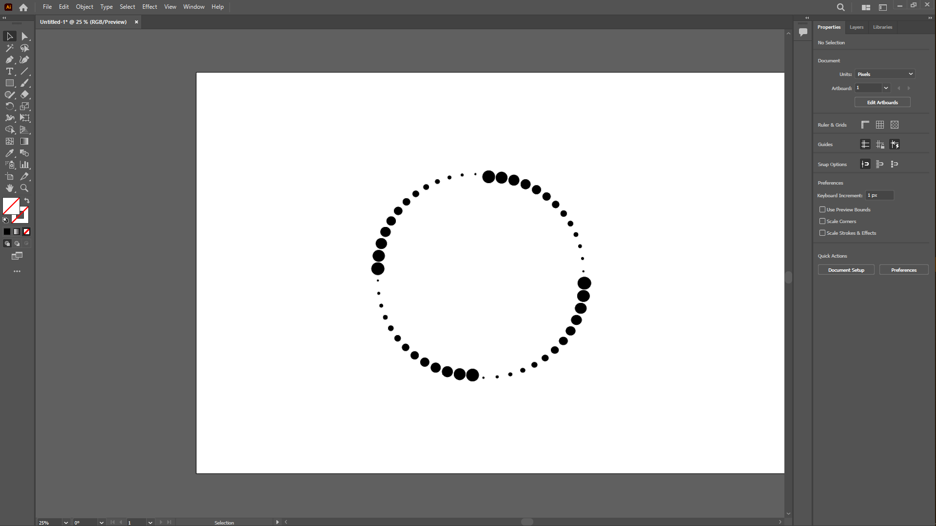
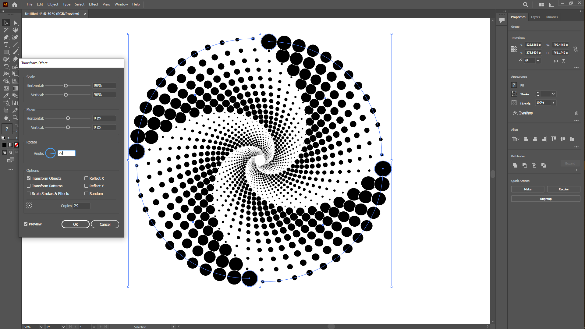
After this i selected and copied both this using CTRL+C then CTRL+F to paste in place then i used the SHIFT+ALT to rotate the copy then i grouped everything then clicked on effect, then Distort & Transform then click on Transform with the window open i set the copies to 29 copies, scaled the horinzotal & vertical to 90% and the angle -9°.
Rastering
I designed something with Photoshop, and so i simply designed the fablab with texture to it, first you open photoshop, click on new file, set the width & height to 3000x2000 pixels, set the artboard to white and then clicked create. i then clicked on brush tools then i clicked on artboard to change its color to blue sot i set the hex characters for this color is 021a41 then i clicked ok then dragged the brush tool over the artboard then made it blue, then i created a new layer, selected the artboard again gave it the hex of 114570 clicked ok then i clicked in the middle of the artwork to created a whitened hollow shape to create a dim light effect, then i used the gaussian blur under blur which is one the setting under filter on the features bar then set the radius 4 again going to filter, then finally noise set the amount to 3, clicked ok then clicked on the artboard to give it that effect, now i selected text on toolbar wrote FABLAB, gave it a black color which is hex number 000000 then i draged to centerize it with the artboard, next you right click on the new layer where we wrote, then rasterize type now i used the shortcut hold CTRL+ALT while simultanoeusly pressing arrow left & top respectively, this will create multiple copies of this layer we working on so depending on how you want the effect to be you can set what you want, i made 39 copies. Now you can double click on the layer to add effect, so under blending options select bevel & emboss , and then set the structure size to 7, go back under blending options select Color overlay, set the blend mode to normal then double click to change the color and give it a hex number of e33601 CLICK OK AND Close
Now that we have applied effect on one layer, we will copy too other layers by selecting it, and right click, then copy layer style then scroll to the last layer you want to apply it too then hold down shift and select that last layer then right click and paste layer
WILDCARD WEEK
For this week i worked around a 2D to machined using a plasma cutter. For 2D i choose to use the illustrator, due to that editing and pattern making is easy to use for me and also most importantly i was going to use this software tracing the image i had downloaded that can be found here to be used on as for machining on plasma cutter. So i downloaded the image below.
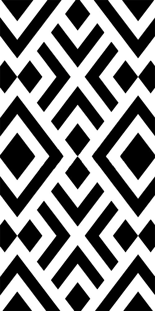
So i opened illustrator, imported the picture above and then selected the picture went on to the right side of the workspac, click on save as then choose a placee in control panel, under properties, there’s quick actions, click on Image trace then choose default then Expand, Next go to FILE, click on save as then choose a place to save and save the file as svg.
After this i went on to generate gcodes using Fabmods, i opened the website then programs, then open program then scrolled down to Shopbot, then under it, you select Mill 2D, it opens up a window then on the left top we load in the SVG, file we saved from illustrator, then below in this window, click on Calculate , automatically the with that file saved
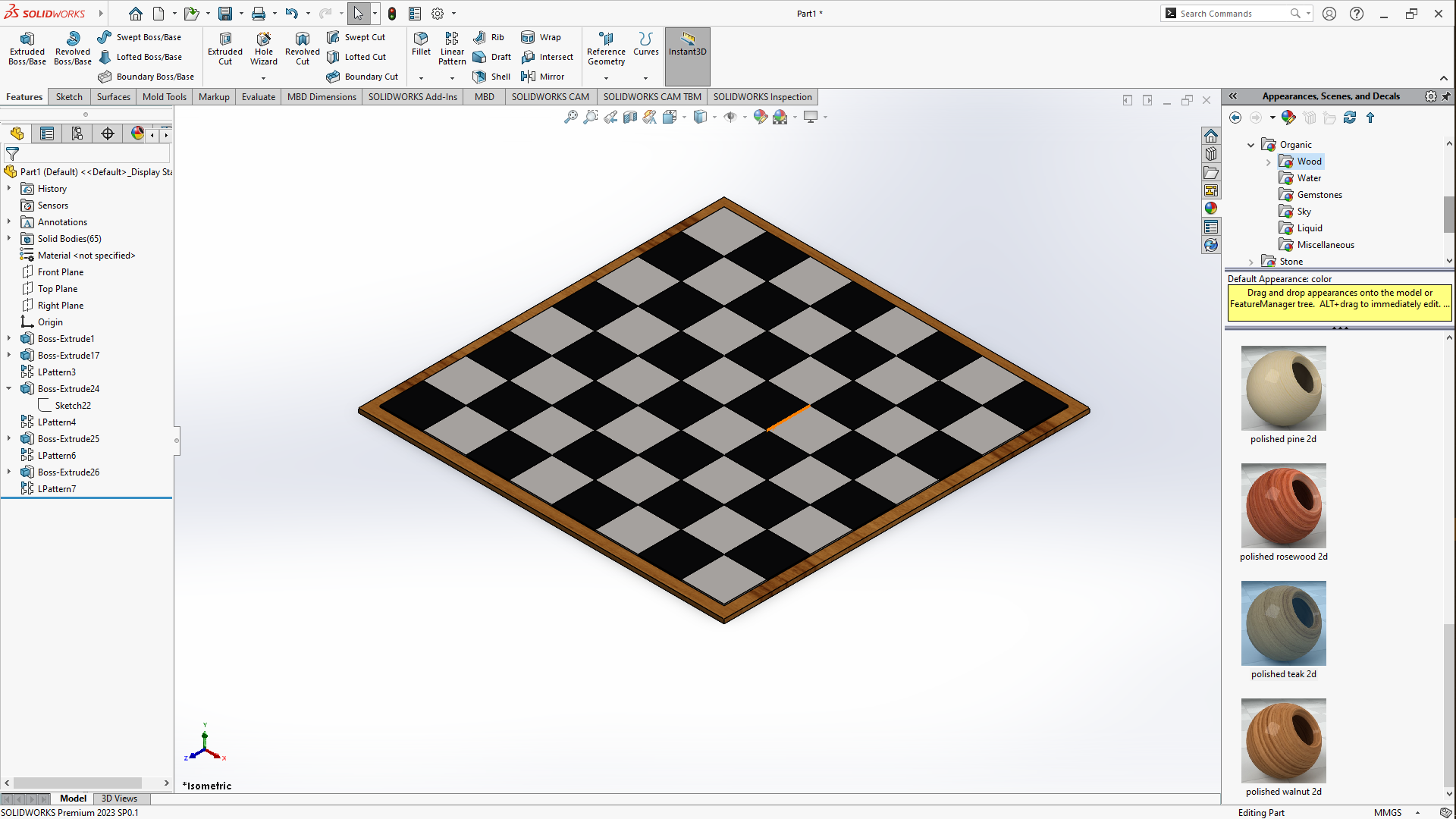
3D MODELLING
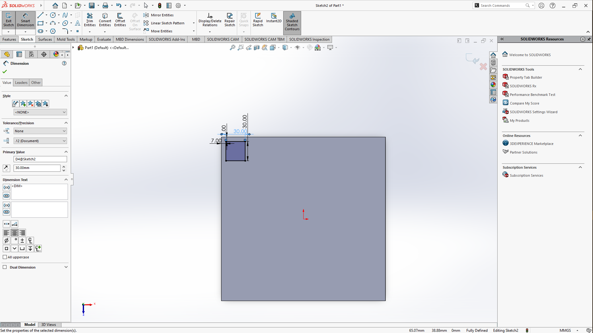
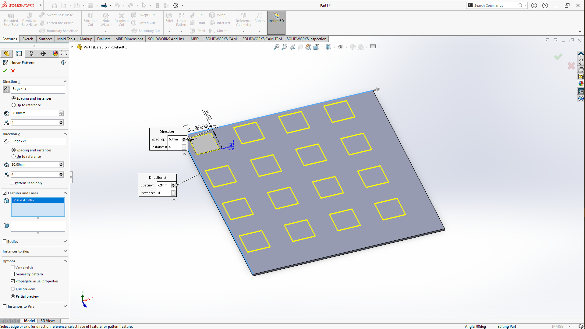
For modelling ironically i had a client ask for a checkers board which gave me the idea for making this as an assignment for this week, so i started off by using solidworks as my 3D modelling software, i choose it because i had used beforehand and also due to its user-friendly interface and intuitive features. So i started by doing a sketch by selecting Top plane, sketch then selectcenter rectangle, drag from the origin to draw a square of 25.5/25.5CM, go to the toolbars, features, then Extrude boss/base the square to 3MM due to the thickness of theMDF, i will be using then i clicked OK. Next i clicked on Extruded boss/base,then selected the top surface, selected the corner square, to create a sketch of 30/30MM, then i put a distance of 7MM between the horizontal and vertical edges then clicked exit sketches then extruded it to 1MM but under where you add the height of the extrusion untoggle the merge resultsbutton to be able to extrude another square next to it. added the color to the square by going to the right of the workspace to Appearances/Scenes and Decals then selected a creamy high gloss plastic.
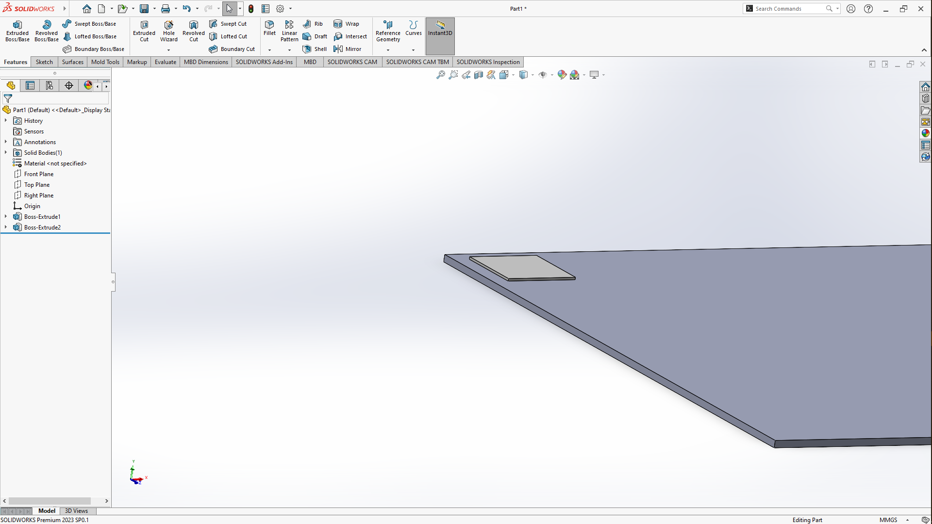
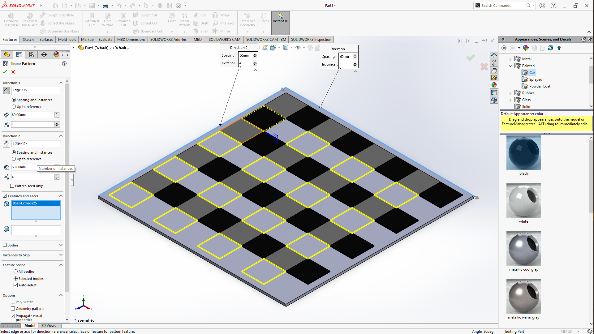
Next in the commands manager, i used linear pattern feature, with its window open, under Direction 1, i selected the vertical edge and for the second Direction 2 i selected the horizontal edges, then set the spacing to 60MM and the squares, i made them four on each direction then i clicked ok to apply the feature
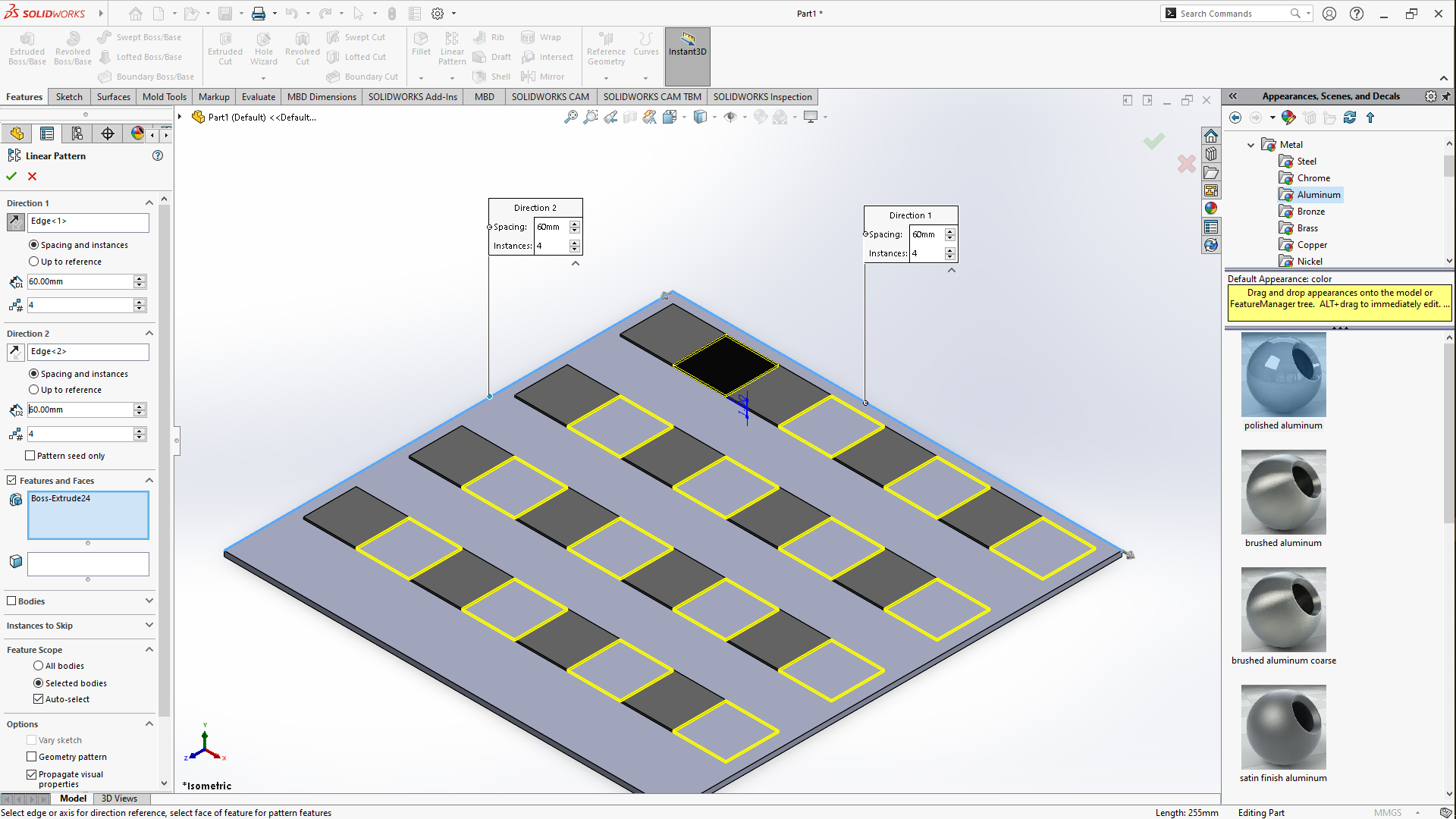
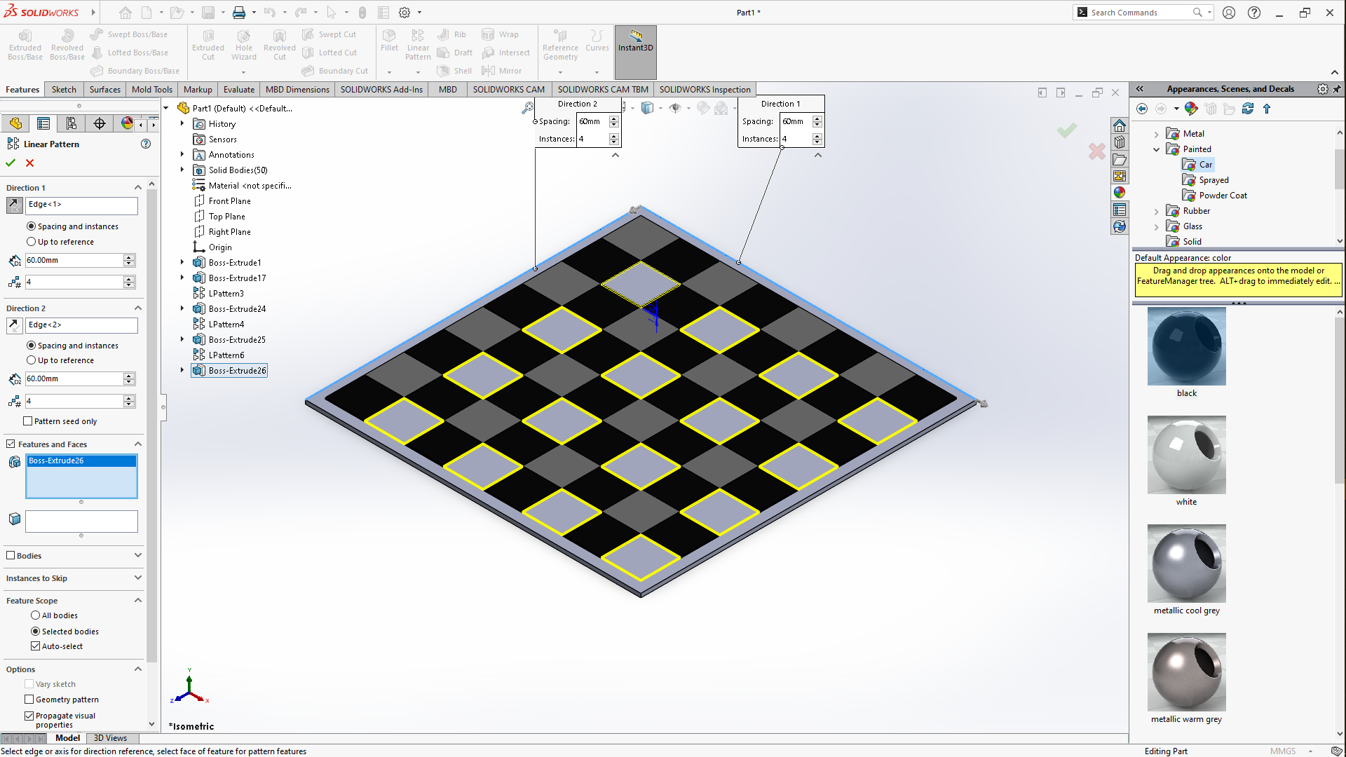
I drew another square of the same size and shape right next to the first one i had drawn then extruded it then repeated the whole process by adding color and more squares using <Appearances/Scenes and Decals and linear pattern feature. At this point we had just created designs for the horizontal side now i repaeted it to make the vertical side too to complete this checkers board. After this i added a wooden texture to the base of the board to finish this. I then saved the files as firts solidworks files then as DXF to put in the coreldraw which is used as a 2D software and and has a plugin to use the laser cutter reason why i saved the 2D dxf type file.
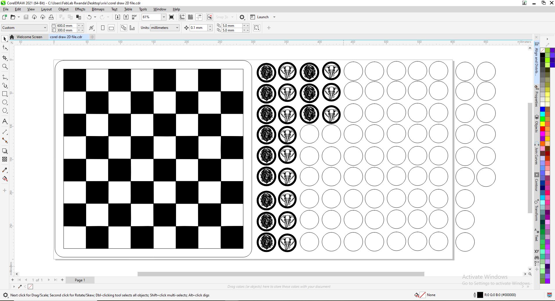
LASER CUTTING & ENGRAVING
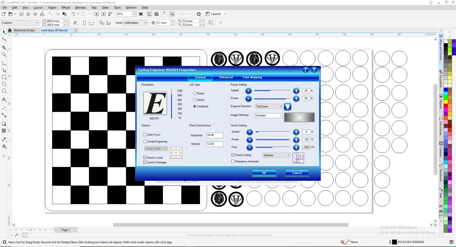
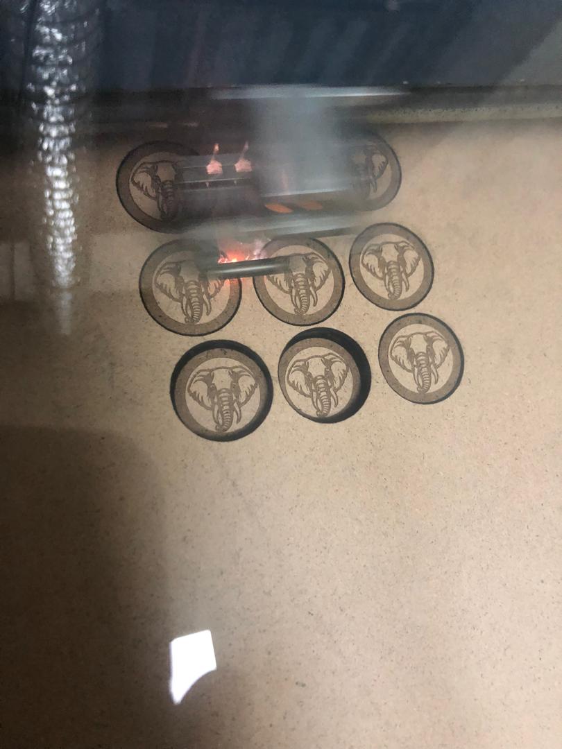
After saving the file from solidworks i exported it in coreldraw to be able to print it on lasercutter machine. The lab is equipped with a 24"x 12"(610 x 305mm) epilog laser, so after importing the svg file i arranged the file on the board as shown below, then after organizing the files on workspace i sent the files on the with the parameters shown below also. Also there’s a point to be made about the pieces, i first downloaded silhouettes of an elephant and the lion too then i made then i traced the photo in illustrator rather than coreldraw due to good quality of tracing by the illustrtor so i opened illustrator, imported the picture above and then selected the picture went on to the right side of the workspace, click on save as then choose a placee in control panel, under properties, there’s quick actions, under it, click on Image trace then choose default then Expand. Now sometimes yo may need to do two more steps like here in this case, next step will be to click on ungroup, then go click on release, then you can separate the image and use it to your satisfaction, after this you save then choose a place to save and save the file as svg. So the files i used will be added in the section at the bottom dedicated for files
the final product
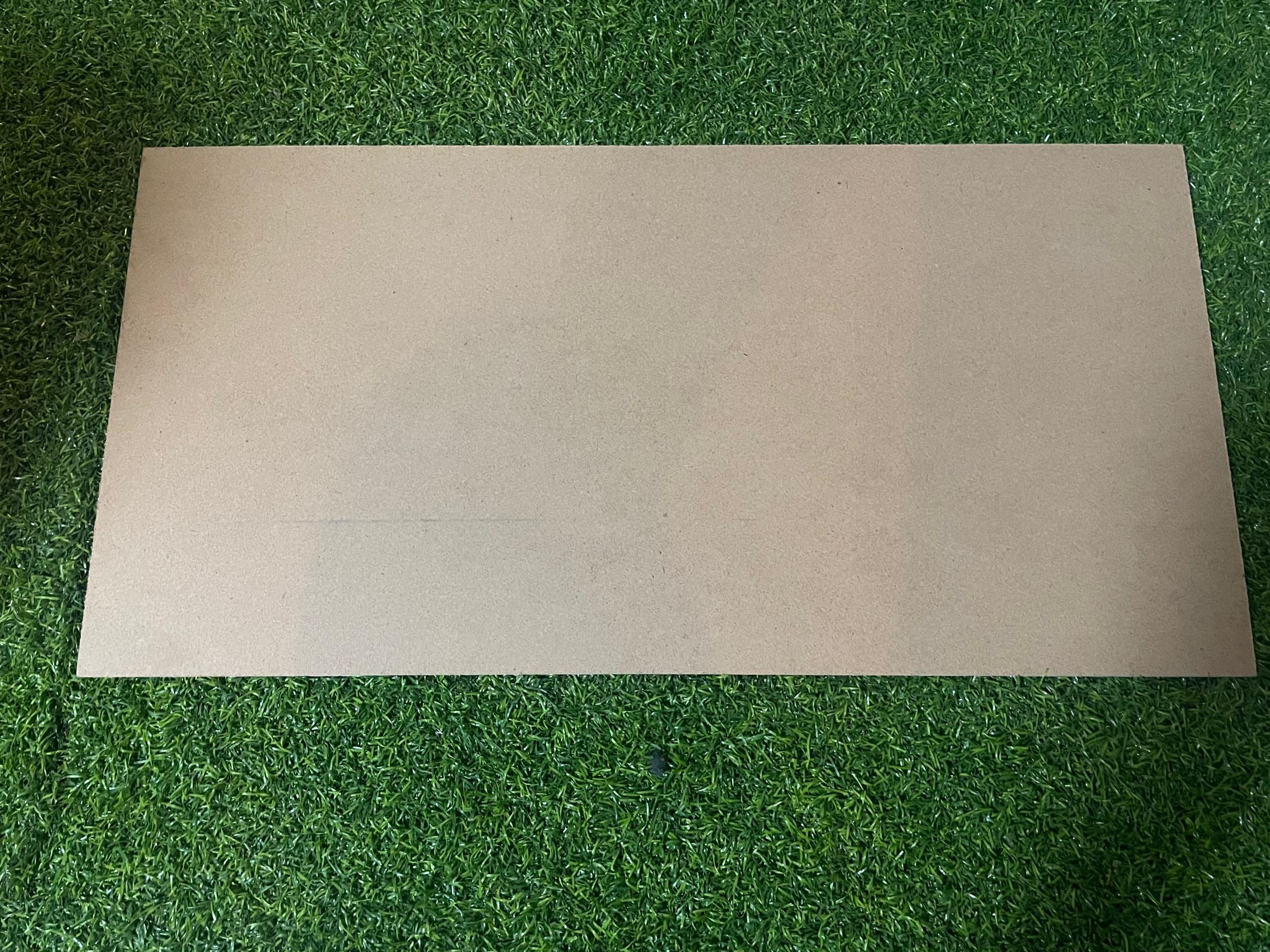
After putting together the design, i sent it to the laser through a plugin controller of coreldraw. Regarding the material i used a 3MM MDF sheet of material, so i place it on the machine bed, you focus the laser pointer on the material correctly, remove the item that helps us to set the focus then pressed start
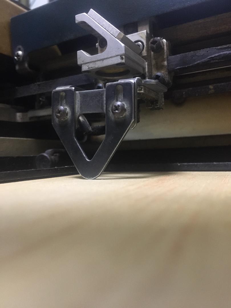
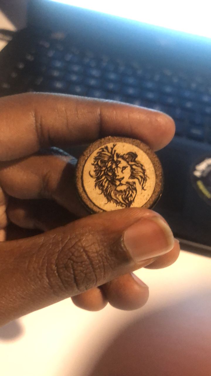
Below are the pictures of the pieces cut by the laser and also below i will be showing in the short hero video of the process while cutting, below are the pictures of the pieces cut before assembling
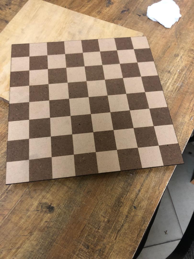
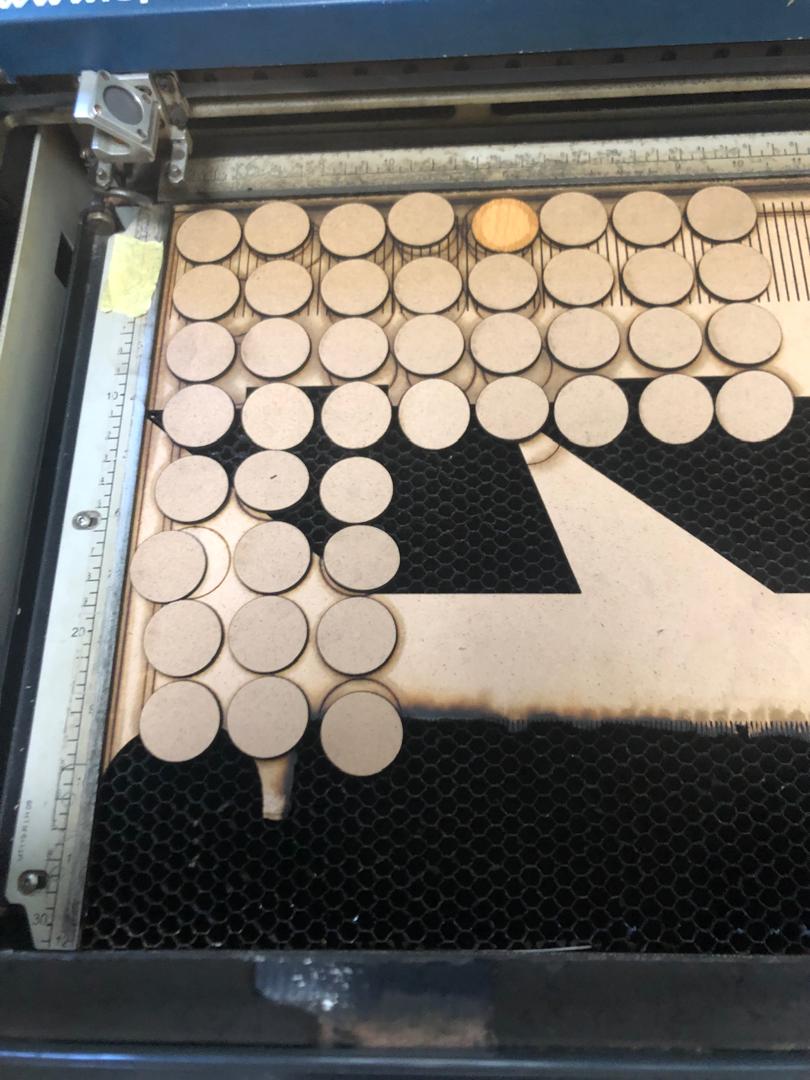
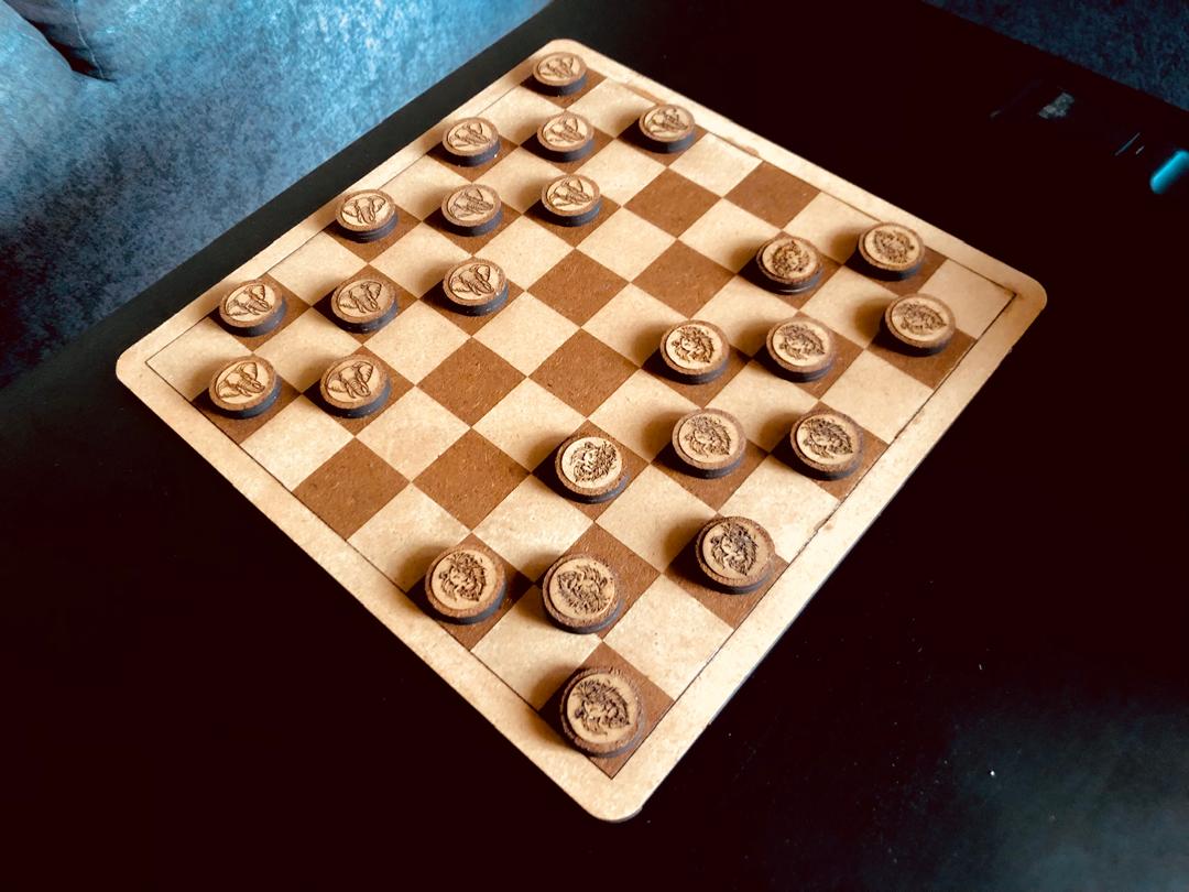
For assembling i had to first glue together the engraved on piece with other two circle of it's same size using AKFIX GLUE in order ot give it a height of 9MM for it to be something that's holdable. I proceeded with glueing the checker board with its contour which gave the final product you see below.
Short hero video
For the short hero i would like to mention that i had a few videos so i used the VEED web to add them together to make one video which is pressented below.
Assignment Files