FINAL PROJECT
Slide
presentation
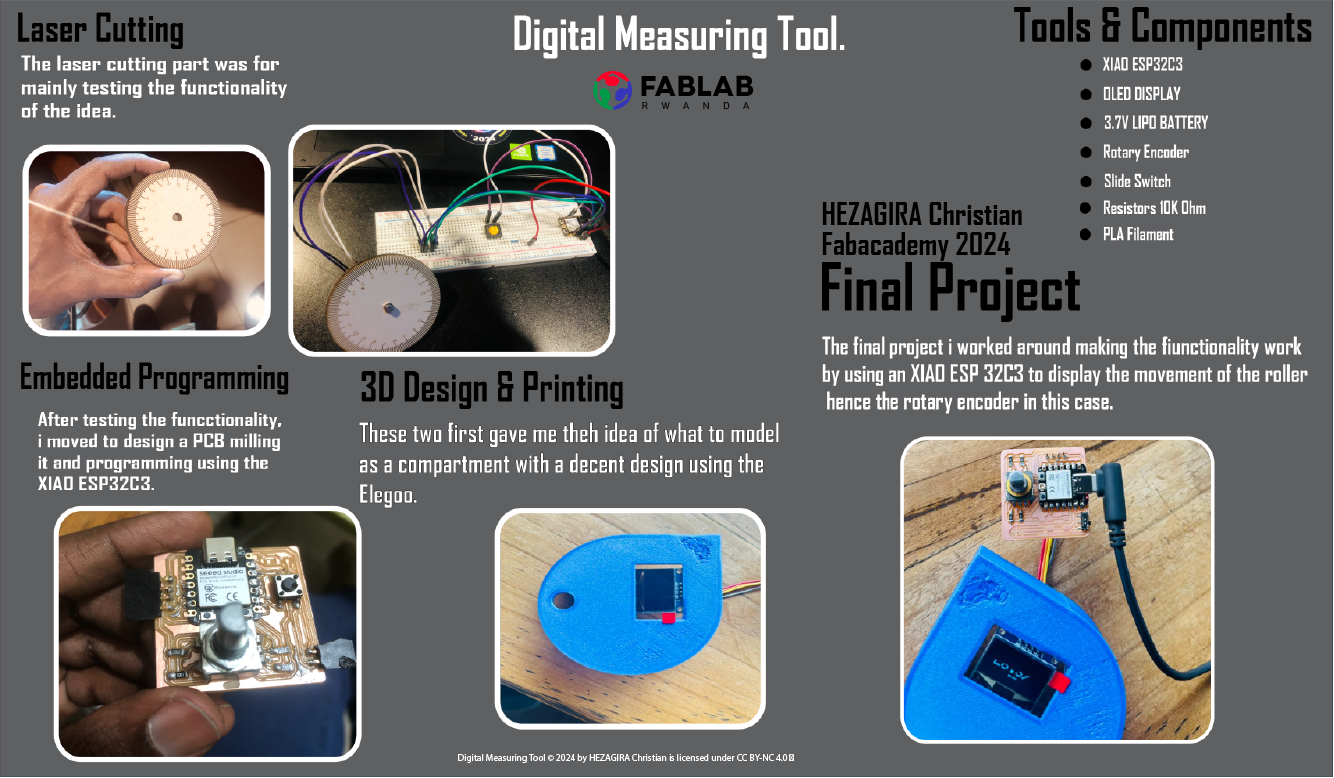
The project itself is about making a Digital Measuring Tape, a modernized version of the traditional tape measure, integrating electronic components for enhanced functionality and precision. Unlike a conventional tape measure with marks and numbers along its length, it will have a digital screen, accurate measurements, that displays measurements in digits, making it easier to read and interpret, for lenghts i intend to make model suitable for construction or industrial use with centimeters as the unit, not too big but one that can also be used to bridge the gap between industrial and other function where the tape measure is needed. for power supply i intend to batteries as the source, lipo in this case
PROCESS PCB MAKING
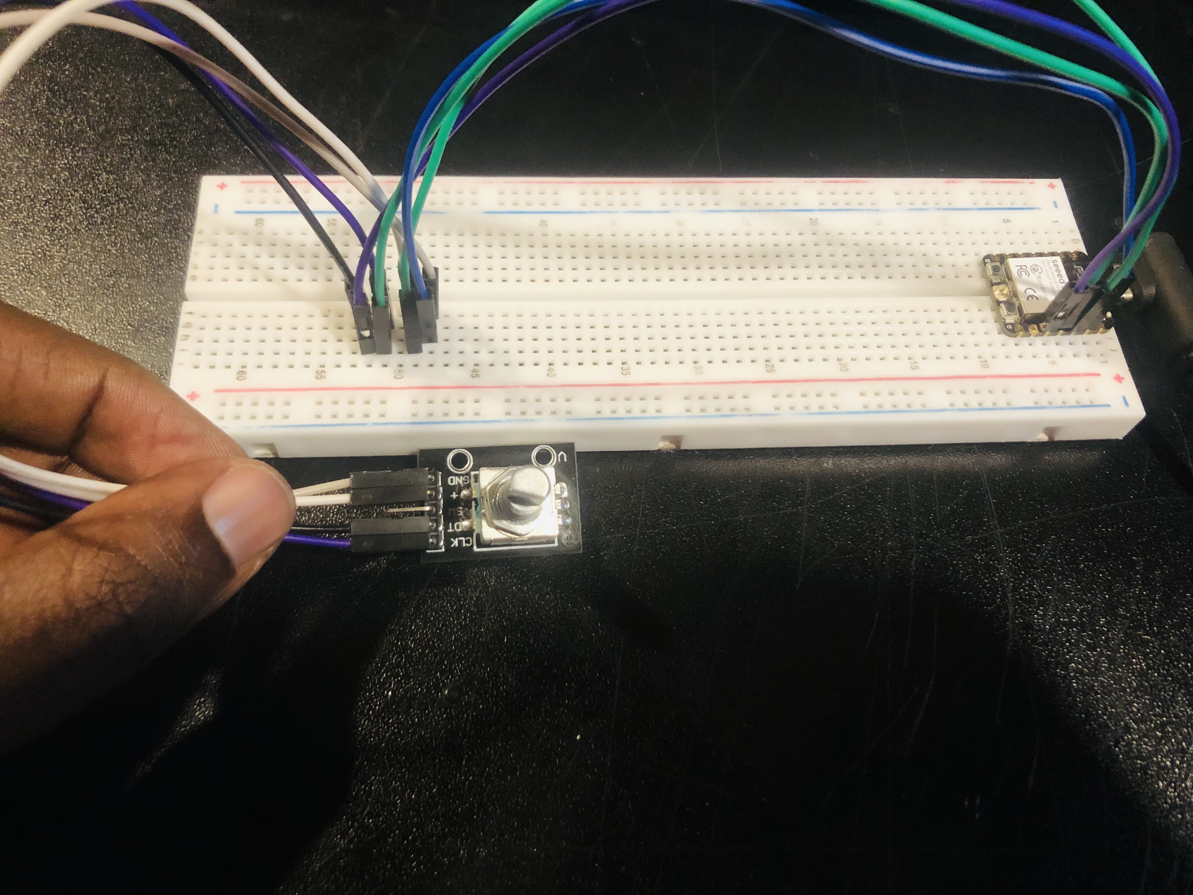
I started off with making connections on the bread to get a better understanding and build a PCB with no errors so i after receiving certain components which i got from this sources below:
CODES & TESTING
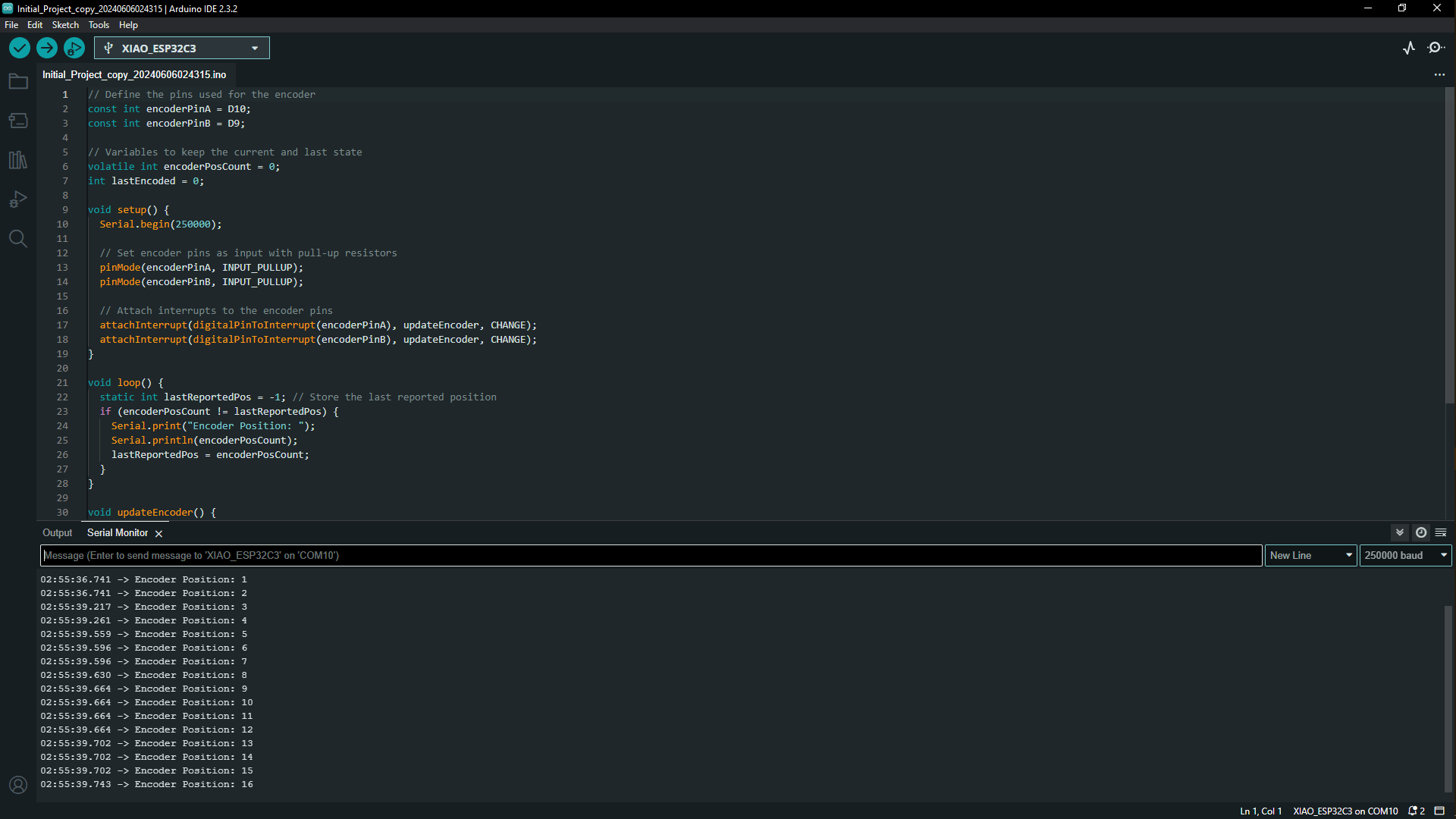
This code initializes the rotary encoder and uses interrupts to update the position count every time the encoder is turned, the result is printed to the Serial port so that you can read it out from the Serial Monitor. I found it online looking for a way to work around and understand how a rotary encoder works so i took the codes from this article to try to see how the encoder will respond and i found it to be positively responding so i kept on building on it so below i will share the codes.
    // Define the pins used for the encoder
    const int encoderPinA = D10;
    const int encoderPinB = D9;

    // Variables to keep the current and last state
    volatile int encoderPosCount = 0;
    int lastEncoded = 0;

    void setup() {
      Serial.begin(250000);

      // Set encoder pins as input with pull-up resistors
      pinMode(encoderPinA, INPUT_PULLUP);
      pinMode(encoderPinB, INPUT_PULLUP);

      // Attach interrupts to the encoder pins
      attachInterrupt(digitalPinToInterrupt(encoderPinA), updateEncoder, CHANGE);
      attachInterrupt(digitalPinToInterrupt(encoderPinB), updateEncoder, CHANGE);
    }

    void loop() {
      static int lastReportedPos = -1; // Store the last reported position
      if (encoderPosCount != lastReportedPos) {
        Serial.print("Encoder Position: ");
        Serial.println(encoderPosCount);
        lastReportedPos = encoderPosCount;
      }
    }

    void updateEncoder() {
      int MSB = digitalRead(encoderPinA); // MSB = most significant bit
      int LSB = digitalRead(encoderPinB); // LSB = least significant bit

      int encoded = (MSB << 1) | LSB; // Converting the 2 pin value to single number
      int sum  = (lastEncoded << 2) | encoded; // Adding it to the previous encoded value

      if(sum == 0b1101 || sum == 0b0100 || sum == 0b0010 || sum == 0b1011) encoderPosCount++;
      if(sum == 0b1110 || sum == 0b0111 || sum == 0b0001 || sum == 0b1000) encoderPosCount--;

      lastEncoded = encoded; // Store this value for next time
    }
2D & 3D MODELLING
Prototyping
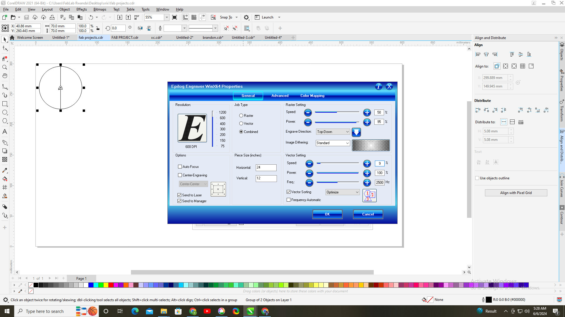
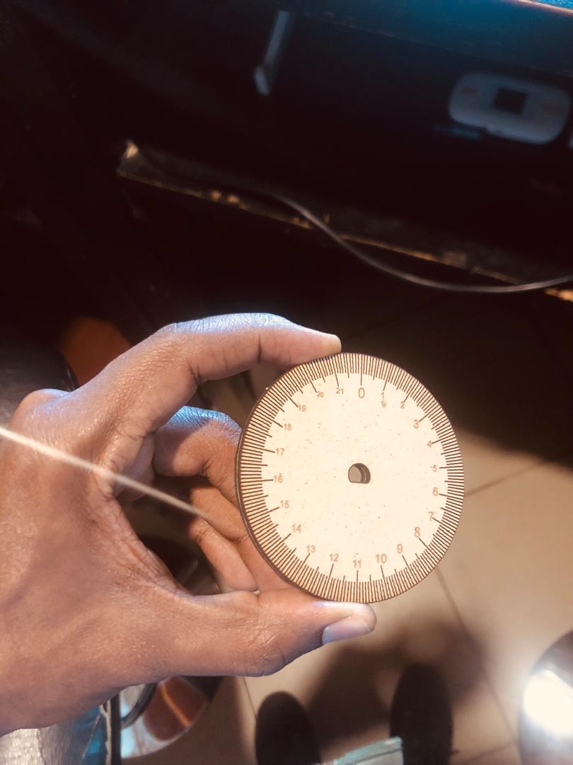
After getting the result that the encoder could function with these codes i designed a roller that's to be the extension of the encoder so again this is an initial design for testing and then progress with what's working. I started with with designing in coreldraw a circle with marked numbers to be able to count the revolution of the roller in conjunction with the pulse of the encoder. So the design is a circle of 70MM with the middle of the circle shaped like the extension of the encoder so that it may fit firmly with the encoder.
I traced or engraved on The circle a line as an indicator of the beginning of a revolution and the end of the revolution to make sure we set up the codes that counts the exact measurement, in other words; how many times the wheel/roller turns while moving it in certain amount of distance. This roller i ended up not using it due to it not having measures traced on it so this can be counted as what didn't work because i ended up not using this.

I designed a second one with measures equating to the diameter of the roller which was wrong because i had to draw around the roller measures equating the circumference of the roller
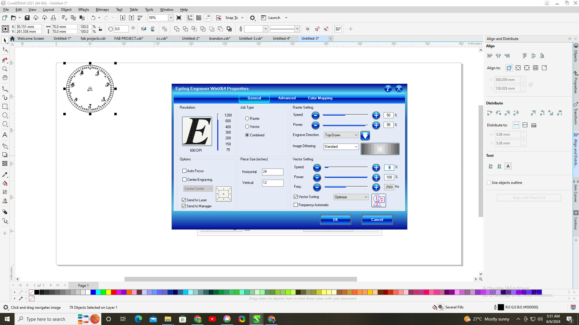
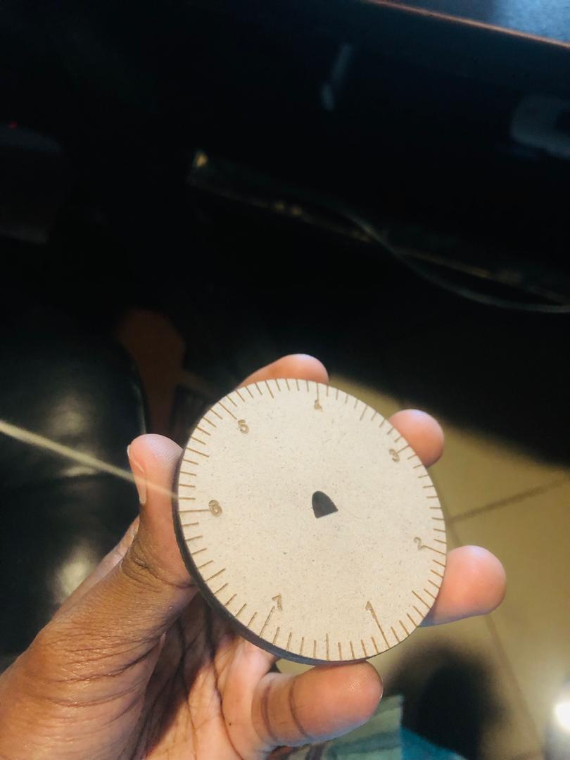
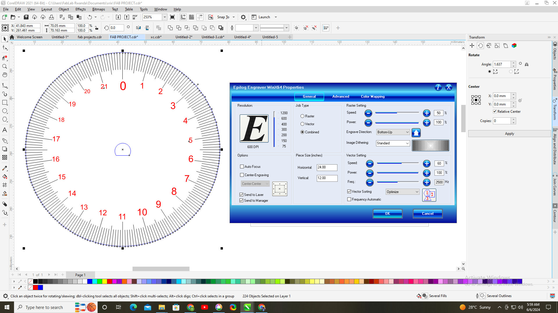
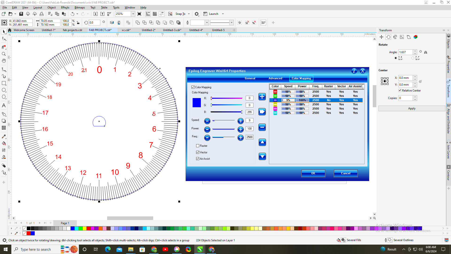
I calculated the circumference using the formula Diameter*π then with the diameter being 70mm, the circumference was 210.905⁓220MM so i designed the roller with a 220MM engraved as i circumference so to design this in coreldraw, you first draw a circle then i add the line of 6mm in height then double click that line and then take its center of rotation put it in the center of circle withe 70MM diameter then go to the properties bar located on the right side of the workspace you can also activate it by using the shortcut; ALT+Enter then go to Transform in its tab, click on Rotate. We will set the angle of rotation to 1.637, this number came from dividing the 360° with the circumference. Below it toggle on rotate the orientation of the object, then set the coopies to 219 since we already have one then print it. For print i learned that another tool called color maping which you can use to cut or engrave part of a same file differently so i wanted the measures to be engraved but i vectorized it so that they can be thin as possible and take less time to do it, then using color map i set the circle to be cut off to a blue color and i cut it using the settings below.
<
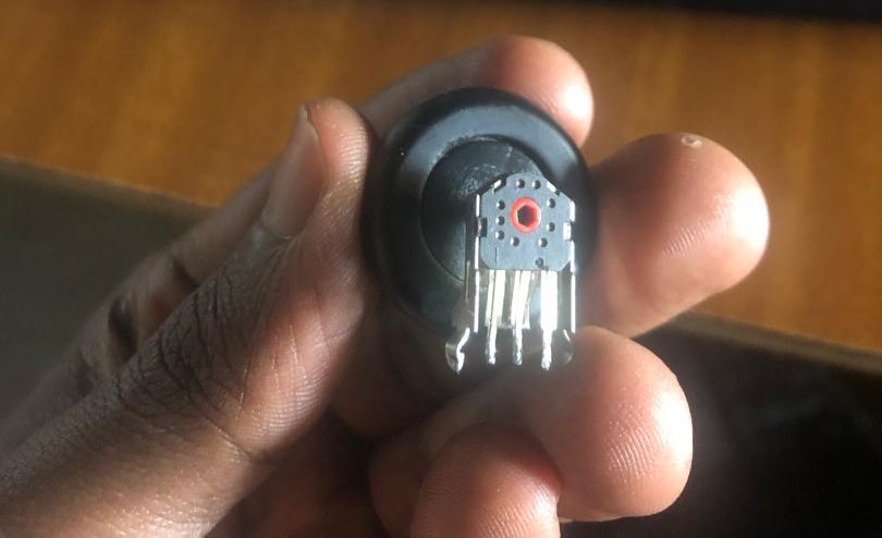
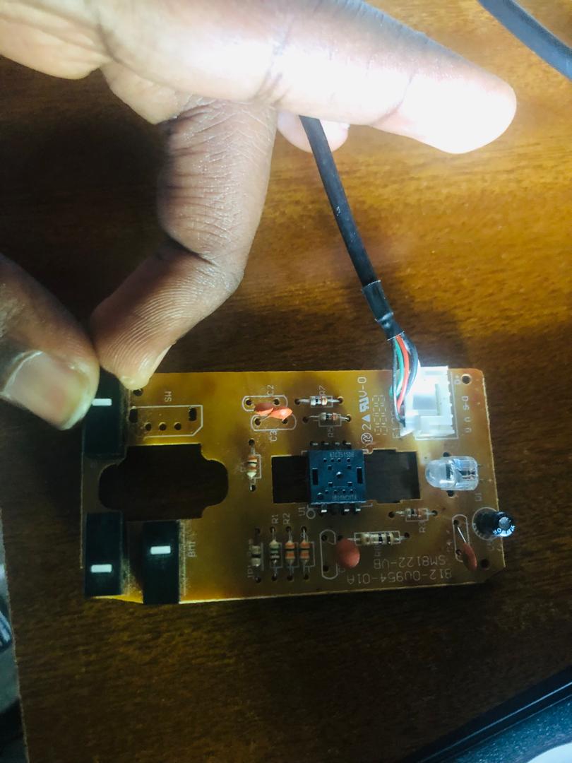
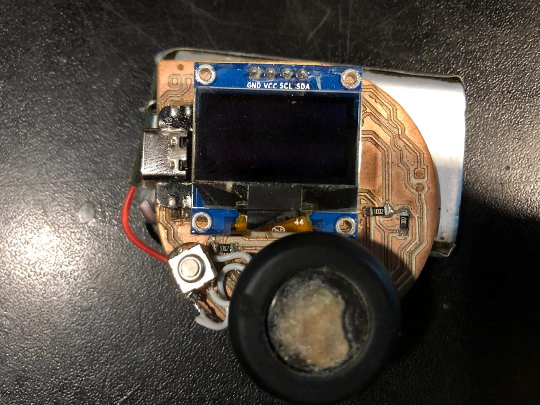
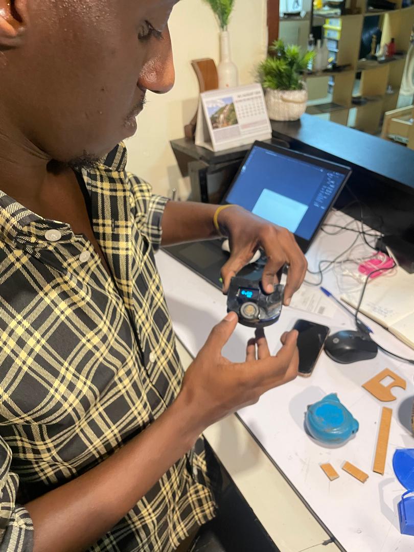
After making & printing these rollers i found that using them will result in slipping and retention on certain surfaces so i decided to use a rubber roller with a Circumference of 78.5MM, so below is a a picture of the roller with its encoder that i took from this board(in the second picture) of the computer mouse.
proceeded with editing the codes to which i added certain functions to the code i found from another simmilar project. The improved line of codes is potrayed below:
    #define ENCODER_PIN_A 8
    #define ENCODER_PIN_B 7

    volatile long encoderCount = 0;
    const float wheelCircumference = 78.5; // in millimeters
    const int pulsesPerRevolution = 24; // Example PPR

    float distancePerPulse = wheelCircumference / pulsesPerRevolution;

    void setup() {
      Serial.begin(9600);

      pinMode(ENCODER_PIN_A, INPUT);
      pinMode(ENCODER_PIN_B, INPUT);

      attachInterrupt(digitalPinToInterrupt(ENCODER_PIN_A), updateEncoder, CHANGE);
    }

    void loop() {
      long count;

      noInterrupts();
      count = encoderCount;
      interrupts();

      float distance = count * distancePerPulse;

      Serial.print("Linear Distance: ");
      Serial.print(distance);
      Serial.println(" mm");
      delay(1000);
    }

    void updateEncoder() {
      int stateA = digitalRead(ENCODER_PIN_A);
      int stateB = digitalRead(ENCODER_PIN_B);

      if (stateA == stateB) {
        encoderCount++;
      } else {
        encoderCount--;
      }
    }
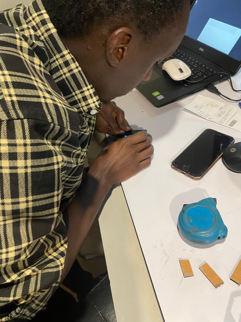
after running the codes i made a few test but first i uploaded the codes to the XIAO_ESP32C3 using a type c cable now to upload the codes you hit the microcontroller boot button then you plug the cable and then you upload it and when it's 100% uploaded you press reset then turn the roller on a specified distance. You start by first measuring an object with normally used tape measure or any other that can take measurement and then use the roller to measure the same object, we found that our roller was taking close to absolute accurate measurement that is in regard to the object that have static known measurements like paper and also using the normal tape measure, so we did couple test, which came pretty close to each others count
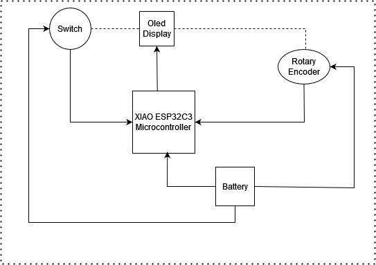
System Diagram
I used draw.ioto create my system diagram because it offers a user-friendly interface and a range of tools for building clear, organized diagrams. Its drag-and-drop functionality made it easy to add and arrange components logically, ensuring the system flow was easy to follow. Additionally, the platform’s customization options allowed me to use colors, shapes, and labels to enhance the diagram's readability, which was particularly useful for visualizing the interactions within the system accurately and effectively.
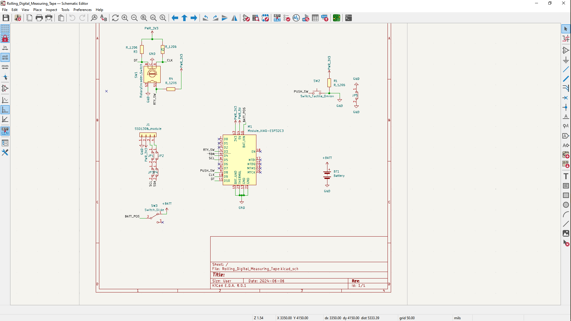
Designing the PCB
i started off by designing the schematic design of the circuit using KICAD a software for making pcb , so in the schematic you can add components to create a cicruit board so i proceeded with updating correctly the schematic to footprints, i saved the front and back layer files to be used with MODS. to generate files to be used by the cnc pcb milling machine.
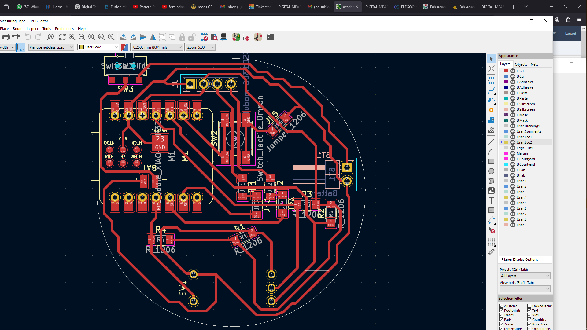
For Milling this pcb i used the MODS. website first, to generate files to be used in the pcb milling machine controller.
Next, i added the png files to the mods website to generate milling machine files, and our lab is equipped with the roland srm 20, so when you open the MODS then right click on the blue-red icons in the top left upper corner, you then scroll down to click on programs which opens up another list of menu then you scroll down to open program, this brings multiple options or machines you scroll down to find the machines your lab uses in my case i scrolled down to select under ROLAND, SRM-20 MILL then under it select MILL2D PCB then with the system open i go under read png, i clicked on select png file, after it has been loaded you click first on Invert then click on mill traces 1/64 under set pcb defaults, next then click on calculate, the process is the same for edge cut and drills expect that these type of files we use mill outline instead of mill traces, so after clicking on calculate its gonna automatically save the file, an rml type file for the milling machine.
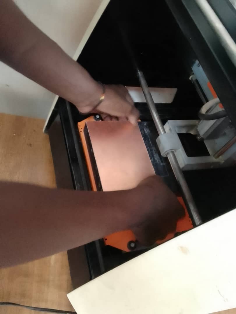
i saved the file then put it on flash drive, connected it to the machine that has the roland srm-20 software for milling then loaded the files to be milled so first the traces the drills (for drilling hokes) then edge cuts for removing the pcb
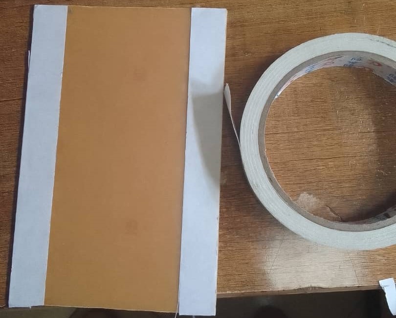
This is setting up copper boards you add a double-sided tape on the back of this pcb in order to be able to stay still on the bed of the machine while the spindle with the tool are tracing on it.
below there's a picture of traces, after this i moved to adding components and soldering next was to start uploading codes to the microcontroller.
.jpeg)
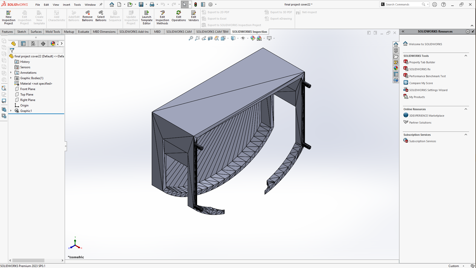
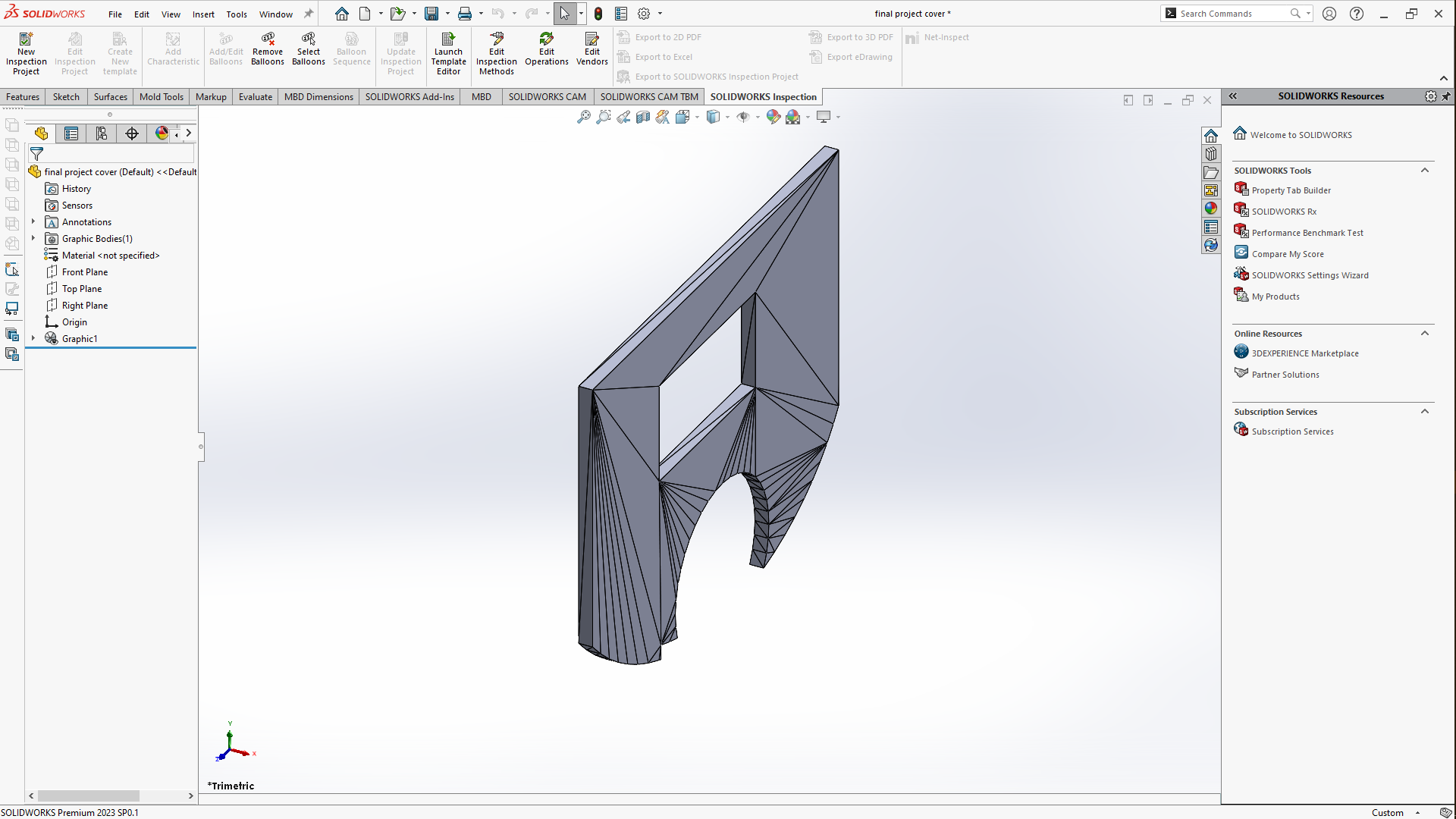
3D Design
For 3D designs i designed the enclosure housing the electronic components and the screen and the roller
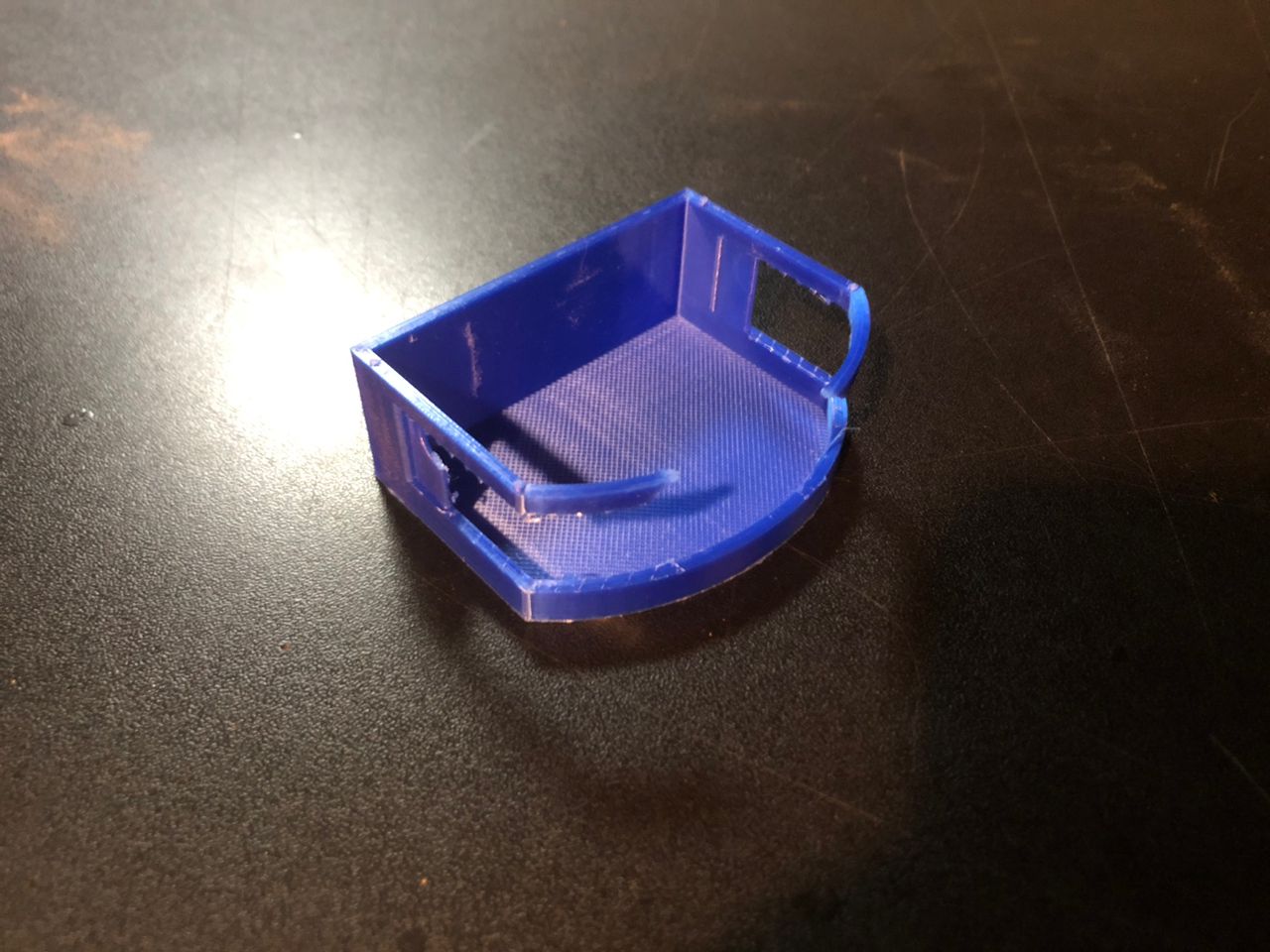
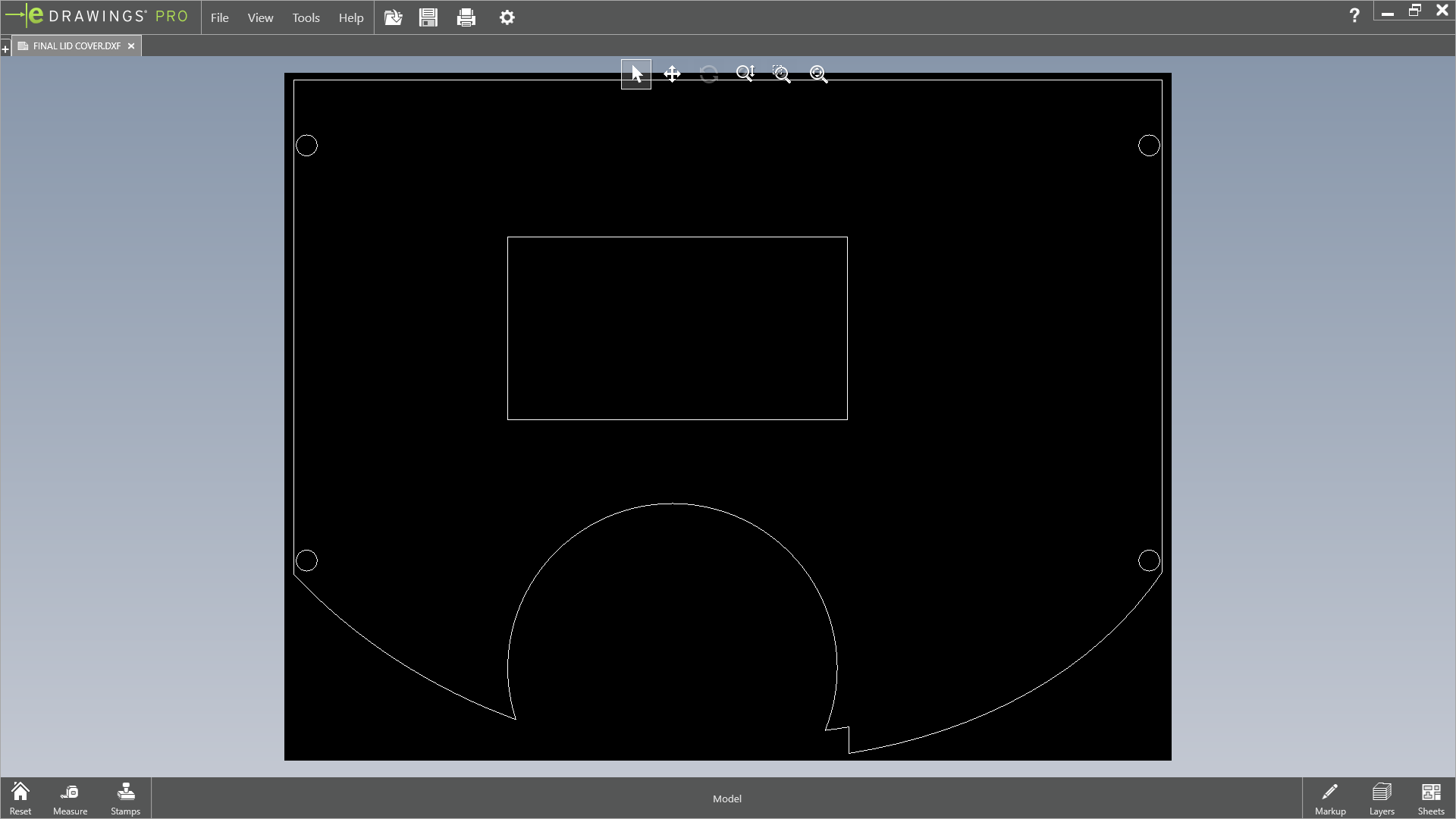
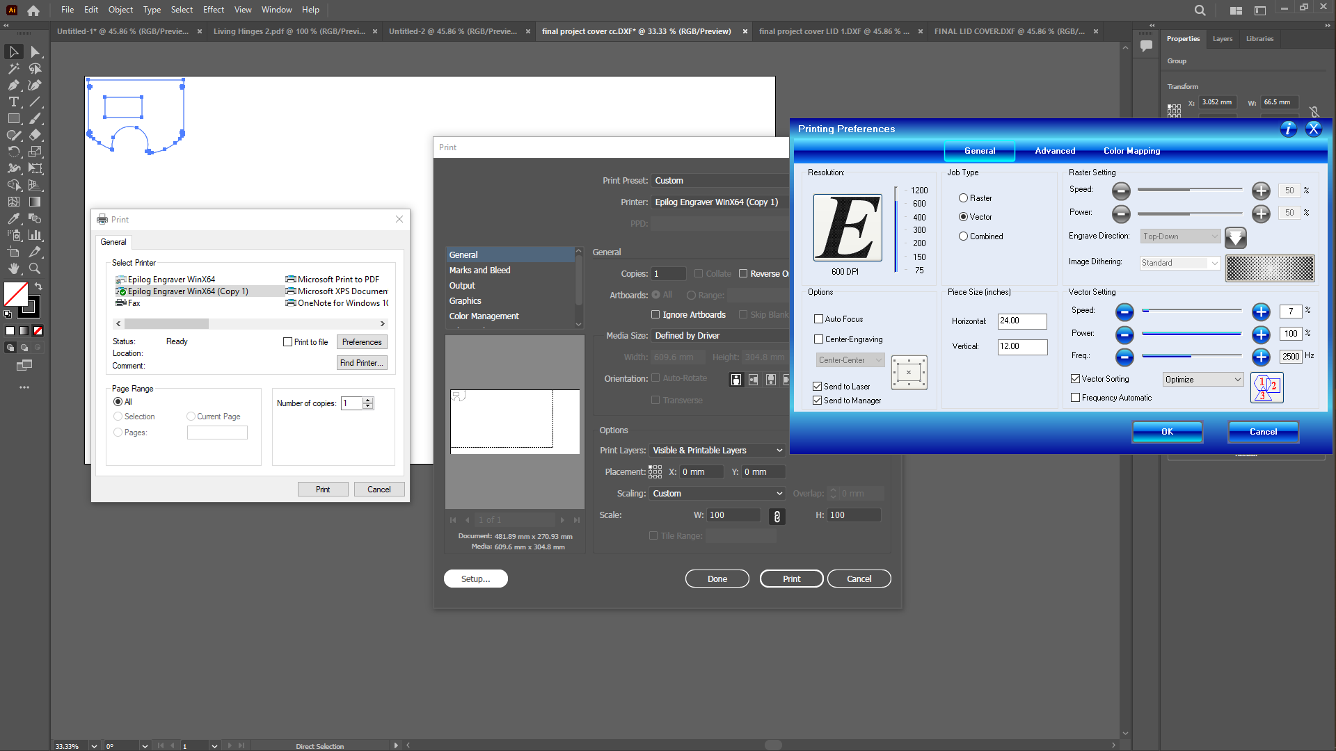
Laser Cutting
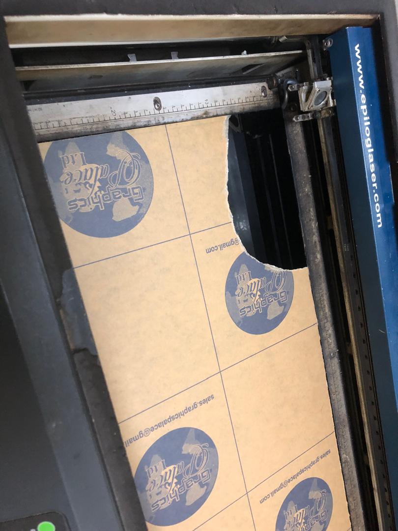
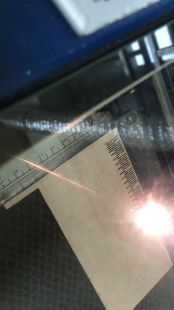
After designing the model in solidworks i made the covering parts of the enclosure using laser cutter i used two material for this, a 3MM black acrylic sheet for using to make a top cover so i saved the front part of the model in solidworks as DXF file to use with vector software for laser cutting, i used illustrator and used it as well to print on the epiloglaser so i saved it first as DXF then i opened a file in illustrator then i placed the black 3MM acrylic sheet on the laser bed(important that you place the side of the acrylic to the back), gave it a focus and then plugged the laser to my computer(the details are elaborated in the picture on the far right),
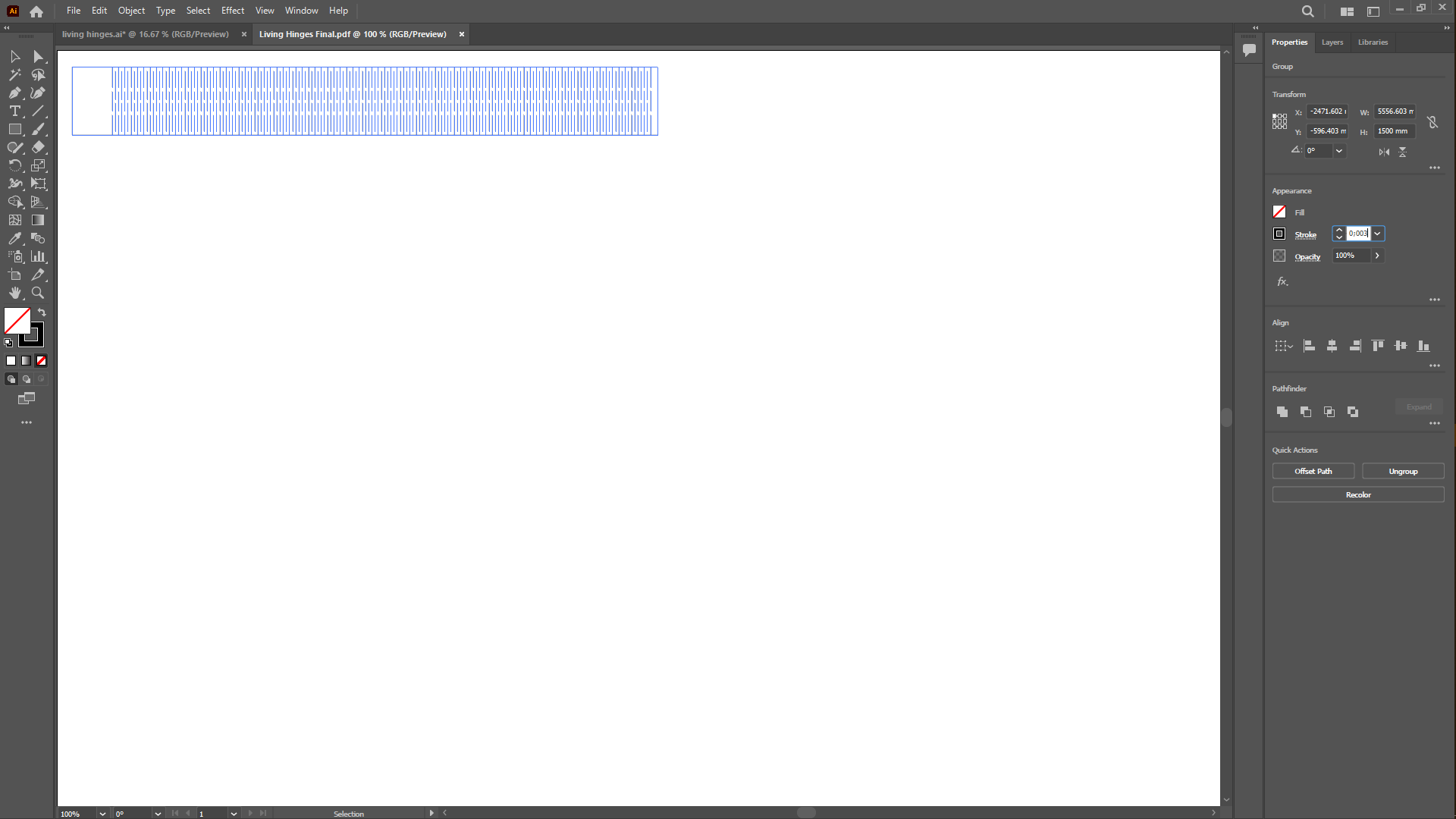
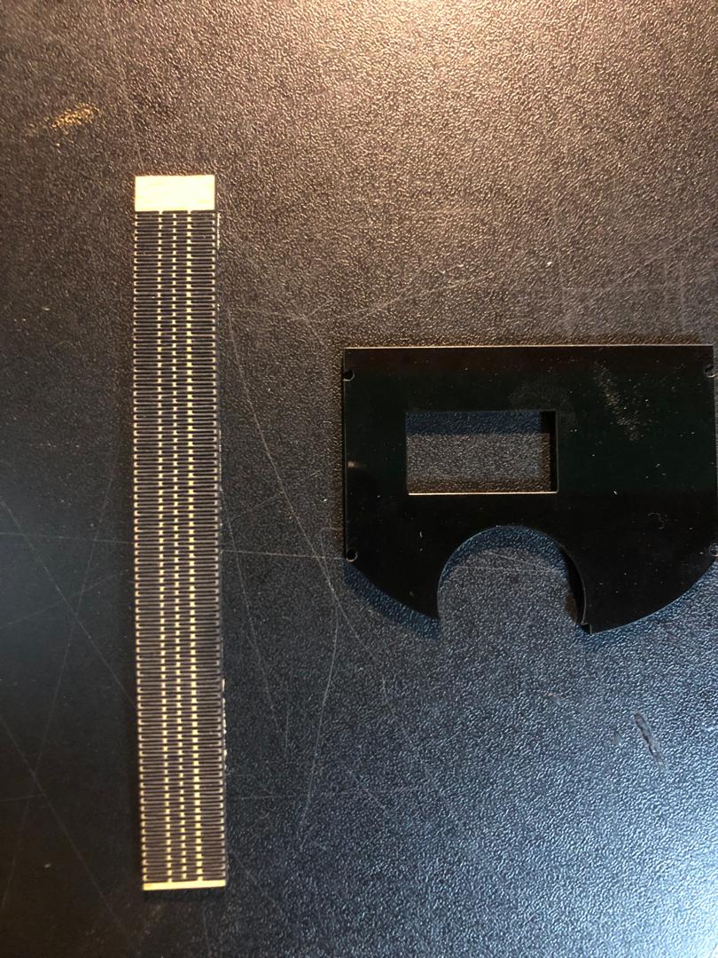
After i measured the distance of the contour left on the middle part of the 3D printed part to be 125MM, to make it cool i choose to use the living hinges with a 3MM MDF sheet. To bend the MDF i used illustrator, traced three dotted lined and spaced them out to a distance of 0.6MM , gave it a contour and grouped the rectangle piece with 125MM of length to 14.5MM of height. So i gave the lines a black stroke then i set the stroke to 0.003PT then i sent the job to the laser using the same cutting setting i used on acrylic.
System Integration
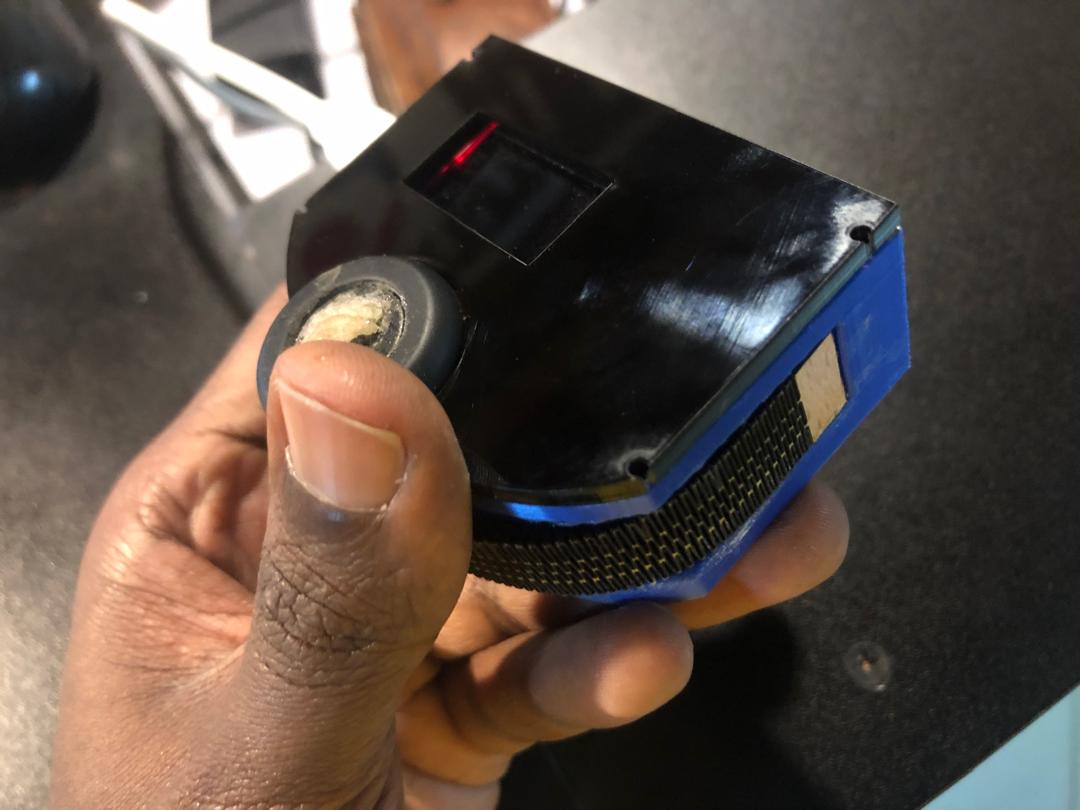
For system intergration i added components on the PCB then attached the battery to the back and then i placed it all in the 3D printed box then added the top acrylic lid and the 3MM mdf that i cut in living hinges for the the MDF to be foldable around the model.
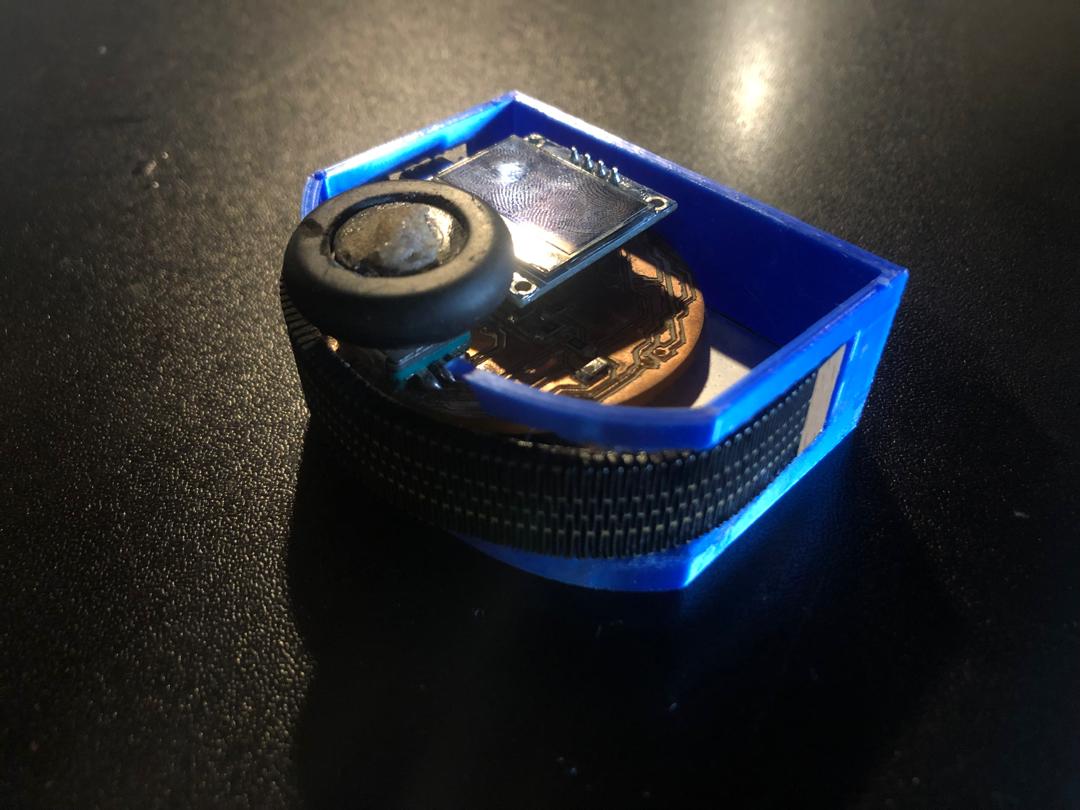
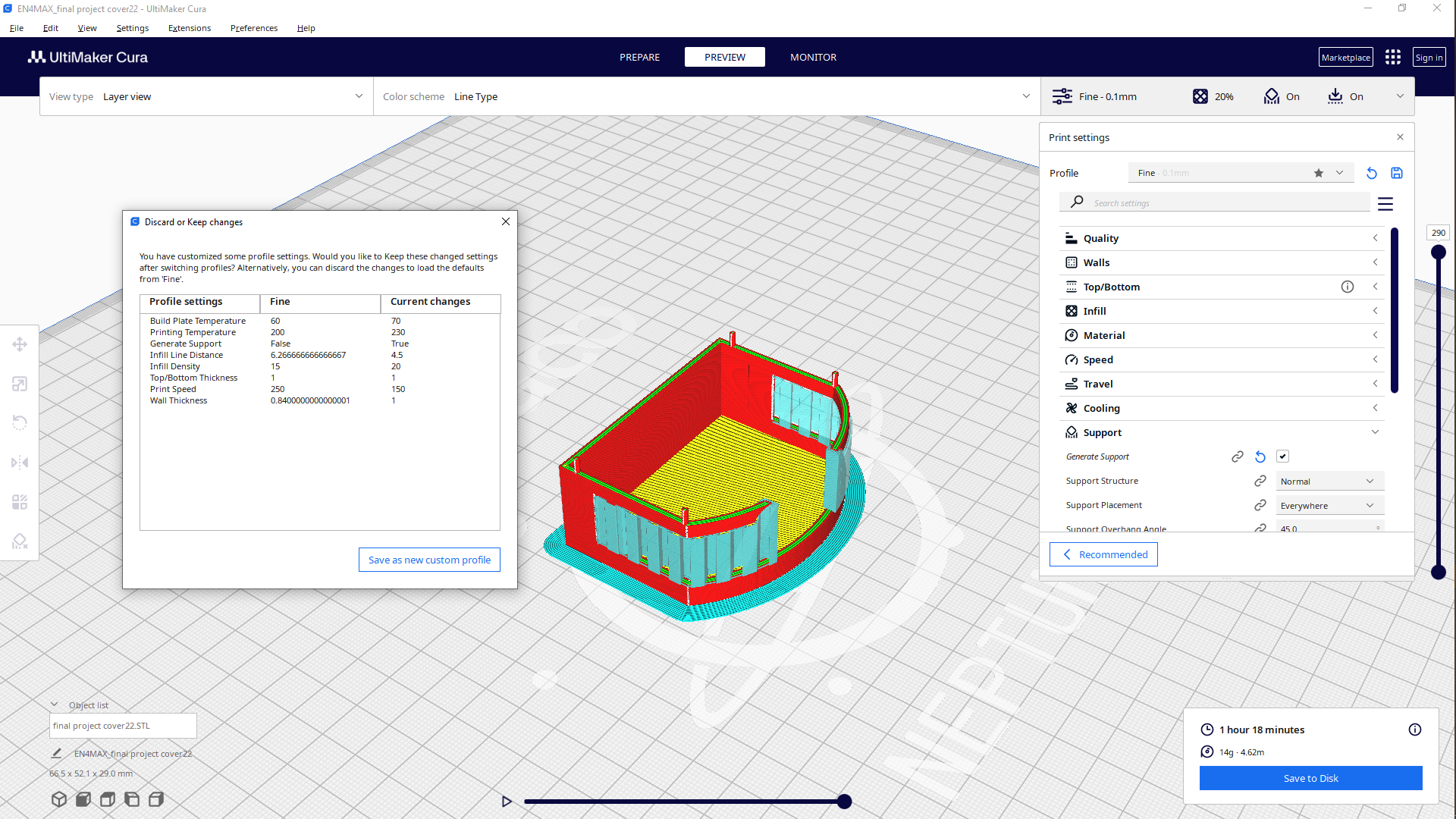
the content below were used before for testing, the final product is different now because these below were made using 3D printer only.
TESTING VIDEO before covering
TESTING VIDEO After covering
So i was aiming at using the 3D printer to print my case but the printer had some update issues and wouldn't print and due to the deadline i ended up using 3MM mdf to make a box to cover the model.
TESTING VIDEO After covering 3D printed parts
BOM
| Item | Quantity | Unit price | Total | Comment | Market Place/Link |
|---|---|---|---|---|---|
| Power Components | |||||
| Li-Po Battery | 1 | $9.90 | $9.90 | For final project | Link |
| Passive Components | |||||
| Resistors | 9 | $0.08 | $0.08 | For final project | Link |
| Electromechanical Components | |||||
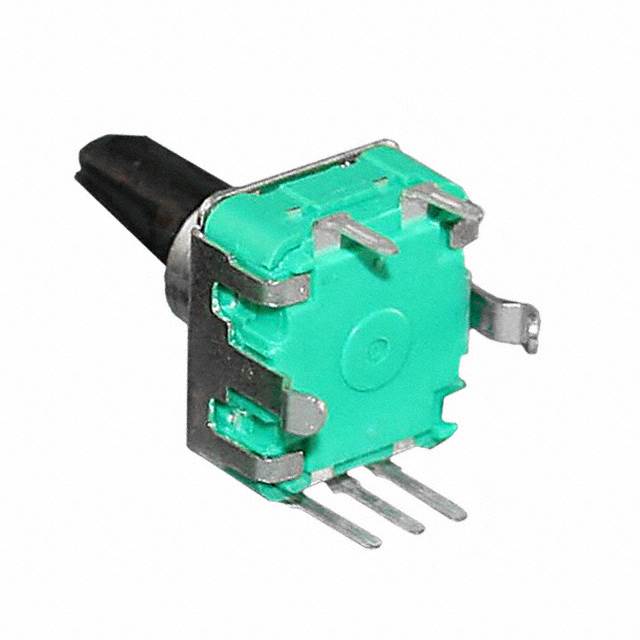
| Rotary Encoder | 1 | 2.97$ | 2.97$ | for the spining roller | Link |
| Switches | 1 | 0.30$ | 0.30$ | for resetting to re-measure | Link |
| Materials | |||||
| PLA | 1 | 52.47$ | 52.47$ | for 3D printing the enclosure case | Link |
| MDF 3MM Sheet | 1 | 11.76$ | 11.76$ | For making living hinges | local shops | Mini Development Board |
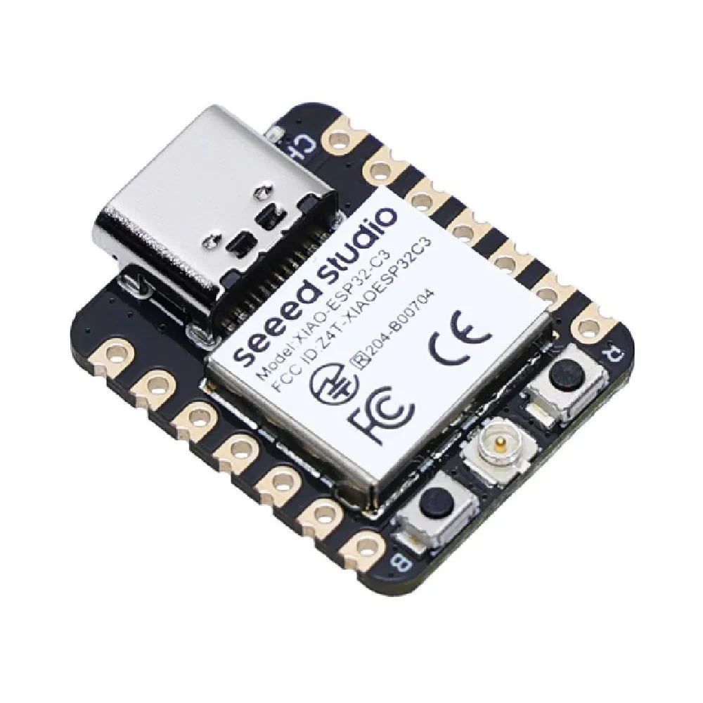
| XIAO ESP32C3 | 1 | 19.80$ | 19.80$ | As a micro controller for the project | Link | Printed Circuit Board(PCB) |
| copper pcb board | 2 | 1.49$ | 2.98$ | final project PCB | Link | Display Components |
| OLED Screen | 1 | 5.45$ | 5.45$ | For displaying the data | Link |
Total: 106.43$
Assignment Files