Week 14
Interface and application programming
The group assignment link can be found here
For this week; i'm supposed to be writing an application that that interfaces a user with an input &/or output device that's controlled by a microcontroller/on a PCB that i made. So i choose platformIO as a user-friendly and extensible/plugin IDE with a set of professional development instruments, to simplify the creation and delivery of embedded products, so to install it you open VS code then go to left side of the window then select extensions, then in the search box you search type platformIO, after searching, click on install then after the installation, restart the VS code. After restarting the VScode you wiil see on the leftside of the window the icon of platformIO then click on it to open it, go to PIOhome under it click on OPEN, then go to New Project, then add a name for your project, select a board name according to your microcontroller you have then click on finish this might take a little tim eif it's time but after that it will open your file to start working on it.
I used the ESP-WROOM-32 to test if the process can work so then i searched the internet for codes or project that was done involving an esp32 how to use MQTT communication protocol with the ESP32 to publish messages and subscribe to topics, so by surfing i found this link, i used the codes from this link to test but since i was going to use it was only for testing so i copied the codes in this article but isince i was going all of them, below were codes i finally used:
  #include
  #include


  // Replace the next variables with your SSID/Password combination
  const char* ssid = "agro";
  const char* password = "mamanb123";

  // Add your MQTT Broker IP address, example:
  //const char* mqtt_server = "192.168.1.144";
  const char* mqtt_server = "172.20.10.2";

  WiFiClient espClient;
  PubSubClient client(espClient);
  long lastMsg = 0;
  char msg[50];
  int value = 0;

  // LED Pin
  const int ledPin = 4;
  void callback(char* topic, byte* message, unsigned int length);
  void setup_wifi();

  void setup() {
    Serial.begin(9600);
    // default settings
    // (you can also pass in a Wire library object like &Wire2)
    //status = bme.begin();

    setup_wifi();
    client.setServer(mqtt_server, 1883);
    client.setCallback(callback);


  }

  void setup_wifi() {
    delay(10);
    // We start by connecting to a WiFi network
    Serial.println();
    Serial.print("Connecting to ");
    Serial.println(ssid);

    WiFi.begin(ssid, password);

    while (WiFi.status() != WL_CONNECTED) {
      delay(500);
      Serial.print(".");
    }

    Serial.println("");
    Serial.println("WiFi connected");
    Serial.println("IP address: ");
    Serial.println(WiFi.localIP());
  }

  void callback(char* topic, byte* message, unsigned int length) {
    Serial.print("Message arrived on topic: ");
    Serial.print(topic);
    Serial.print(". Message: ");
    String messageTemp;
    int c =0;

    for (int i = 0; i < length; i++) {
      Serial.print((char)message[i]);
      messageTemp += (char)message[i];
    }
    Serial.println();

    // Feel free to add more if statements to control more GPIOs with MQTT

    // If a message is received on the topic esp32/output, you check if the message is either "on" or "off".
    // Changes the output state according to the message
    if (String(topic) == "esp32/output") {
      Serial.print("Changing output to ");
      if(messageTemp == "on"){
        Serial.println("on");
        digitalWrite(ledPin, HIGH);
      }
      else if(messageTemp == "off"){
        Serial.println("off");
        digitalWrite(ledPin, LOW);
      }
    }
  }

  void reconnect() {
    // Loop until we're reconnected
    while (!client.connected()) {
      Serial.print("Attempting MQTT connection...");
      // Attempt to connect
      if (client.connect("ESP8266Client")) {
        Serial.println("connected");
        // Subscribe
        client.subscribe("esp32/output");
      } else {
        Serial.print("failed, rc=");
        Serial.print(client.state());
        Serial.println(" try again in 5 seconds");
        // Wait 5 seconds before retrying
        delay(5000);
      }
    }
  }
  void loop() {
    if (!client.connected()) {
      reconnect();
    }
    client.loop();

    long now = millis();
    if (now - lastMsg > 5000) {
      lastMsg = now;

      // Temperature in Celsius
      int c=1000;
      // Uncomment the next line to set temperature in Fahrenheit
      // (and comment the previous temperature line)
      //temperature = 1.8 * bme.readTemperature() + 32; // Temperature in Fahrenheit

      // Convert the value to a char array
      char tempString[8];
      dtostrf(c, 1, 2, tempString);
      Serial.print("Temperature: ");
      Serial.println(tempString);
      client.publish("/temperature", tempString);
    }
  }
installing and Using Mosquitto for Windows
Mosquitto is an application for the MQTT protocol. It can be used as a broker, subscriber and publisher. We will be using Mosquitto as an application, not as a Windows service.You can download Mosquitto here based on your operating system you're running.
Installing the MQTT
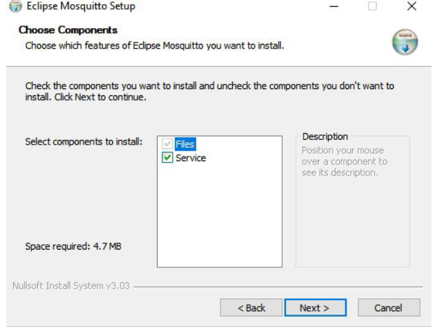
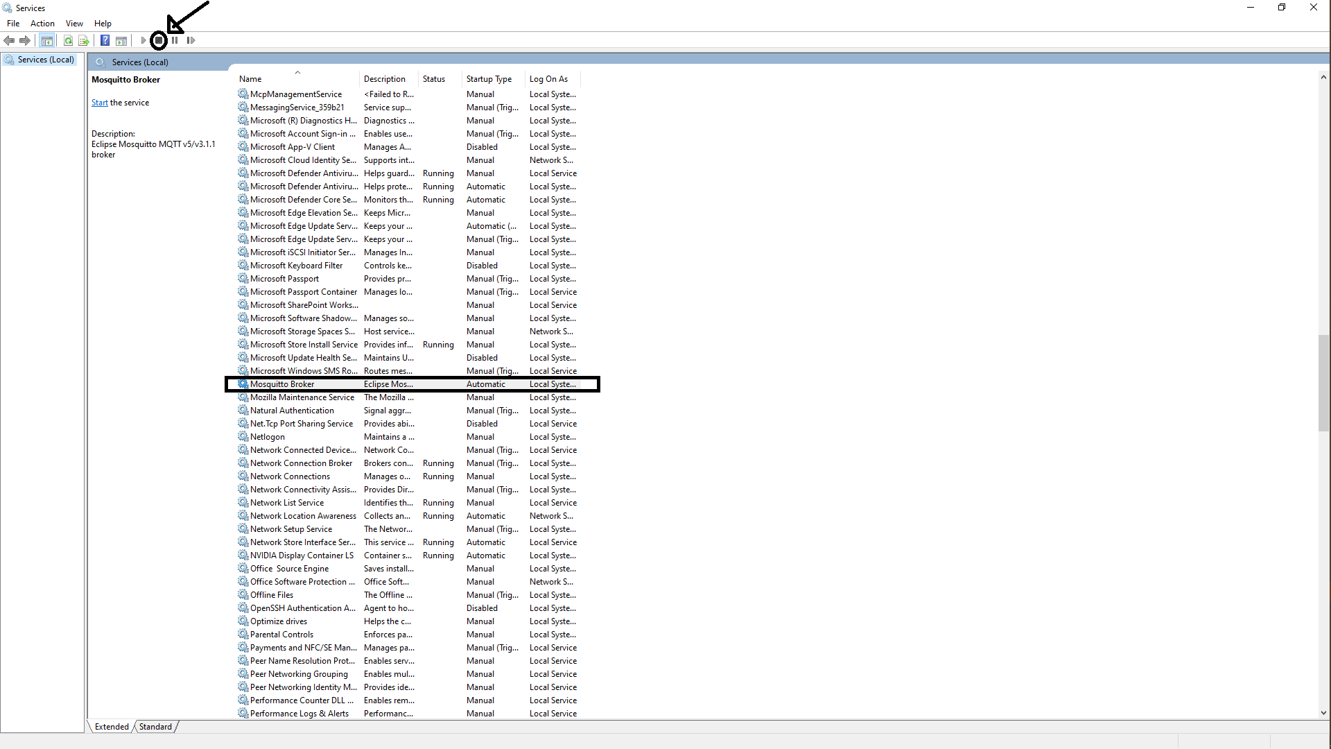
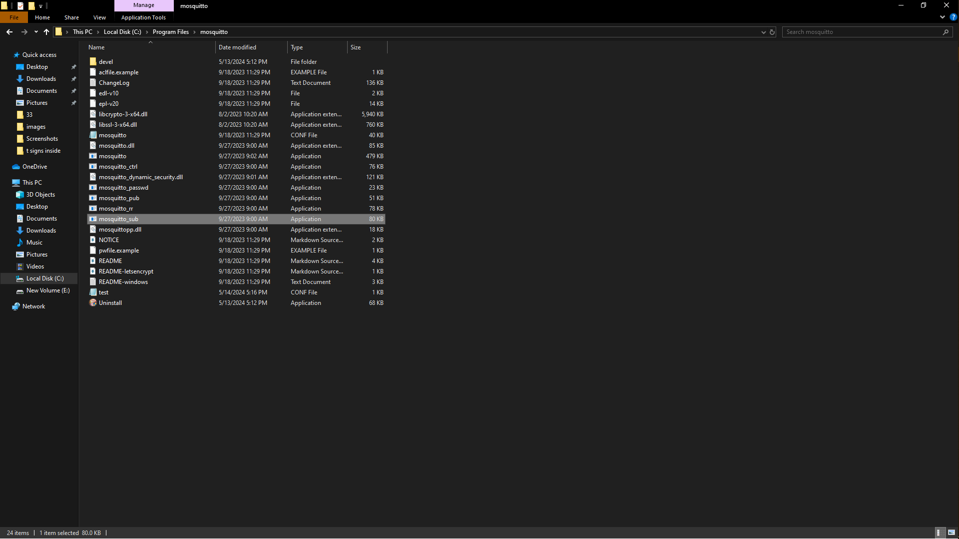
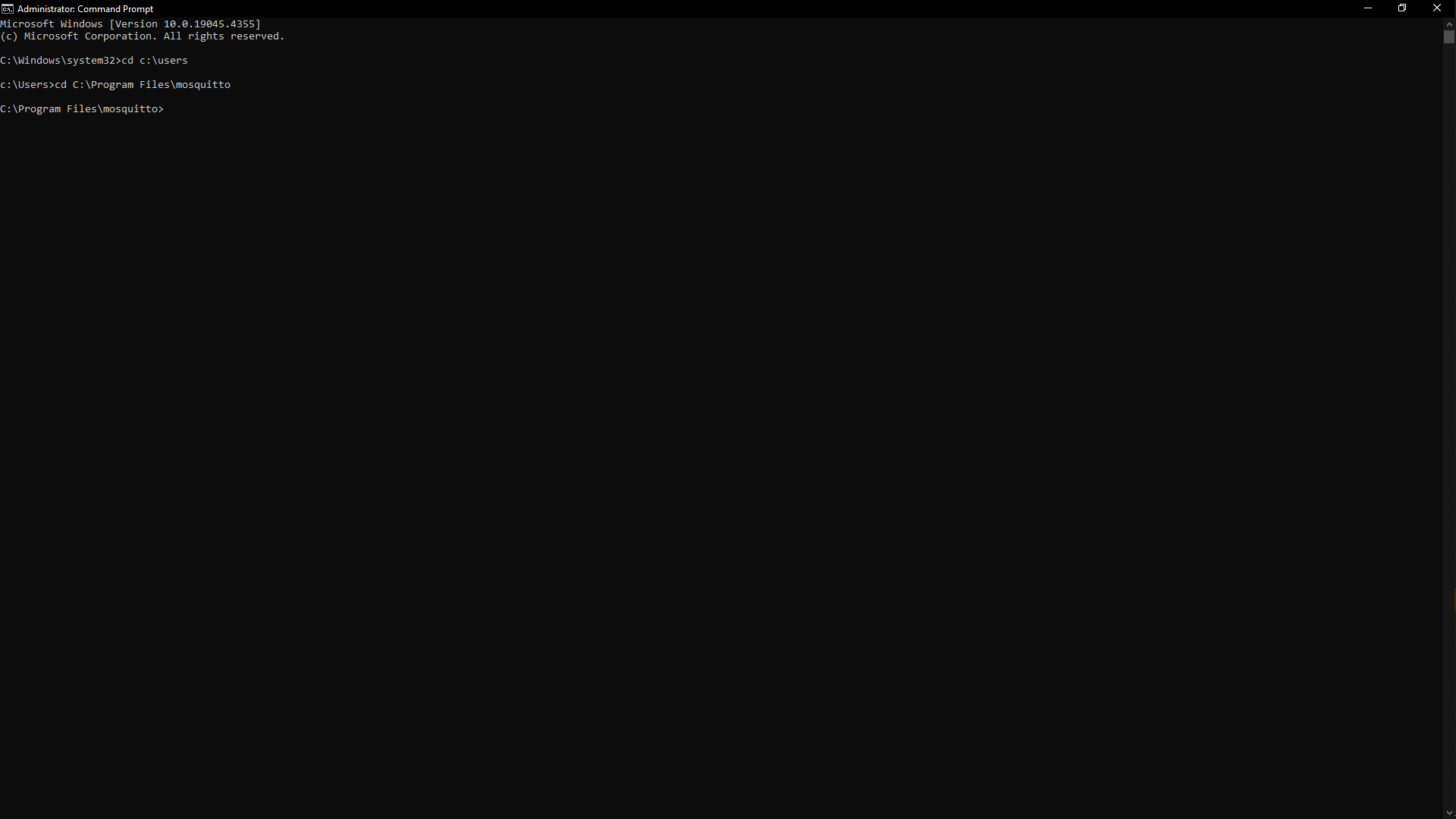
If you install it with the “Service” checkbox checked, it will start automatically with Windows and occupy the default port 1883. If you installed Mosquitto this way you can disable the service by going into the Services menu in Windows and pressing the stop button with the Mosquitto Broker selected and If you installed Mosquitto this way you can disable the service by going into the Services menu in Windows and pressing the stop button with the Mosquitto Broker selected. The default installation path will be: C:\Program Files\mosquitto if the program installed correctly. Next go to windows, open the command prompt by running it as an admnistrator and add the location of where the folder of the mosquitto is saved but if it opens up like this at first C:\Windows\system32>, just add this in front of the cd c:\users then press enter then add cd C:\Program Files\mosquitto in front of cd c:\users then press enter.
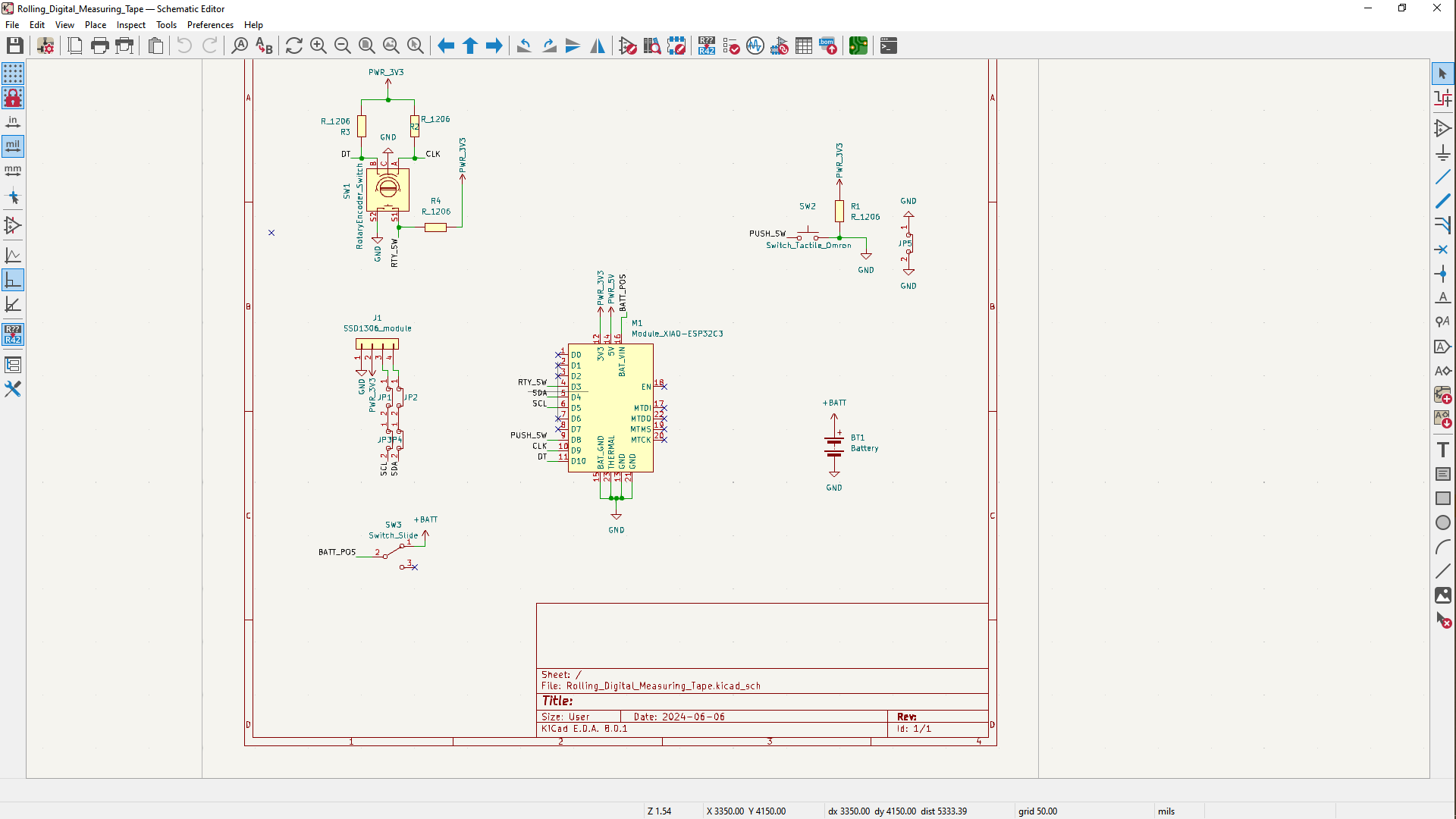
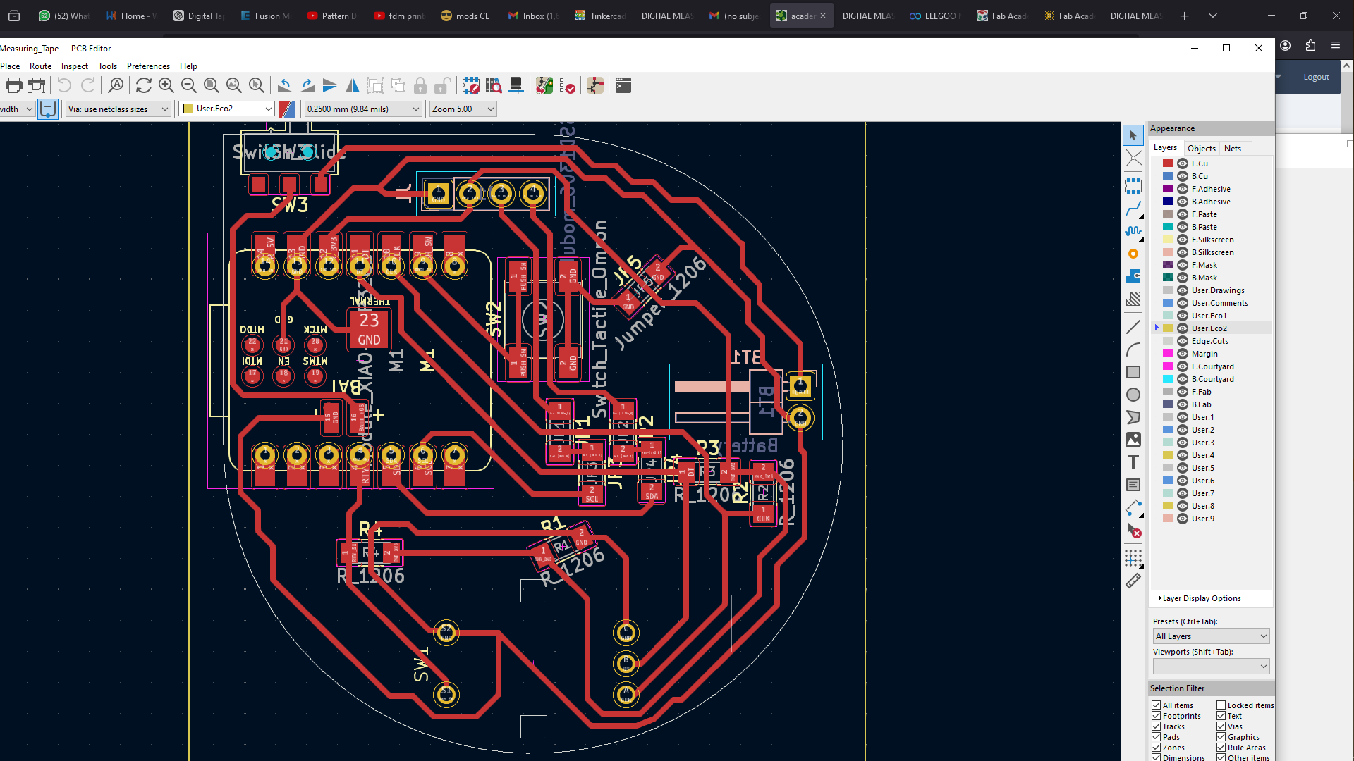
The board i was using, with the ESP-WROOM-32 microcontroller was damaged through debugging so i switched to working with the one i made to use on my final project which is the XIAO ESP32C3 then i ll add the files of the board in the assignment files.
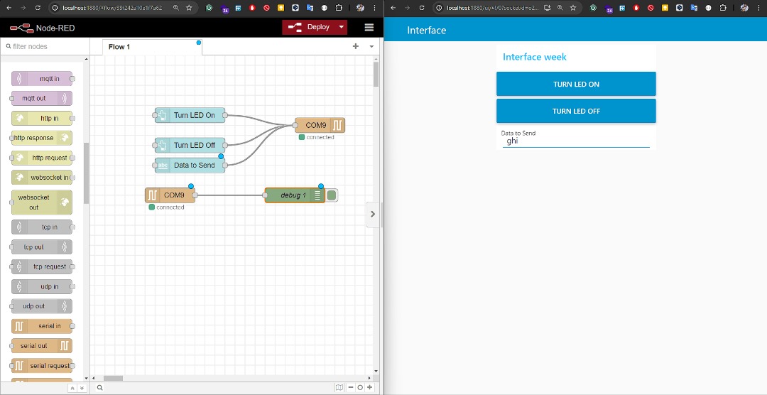
So the idea was to send data on our SSD1306 OLED to interface through installation of node-red dashboard.
Microcontroller
I designed this during the project finalisation but also found that i could use for inteface the files for this pcb will be added at the bottom of this page with other files in the assignment files
Node-RED is a flow-based programming (a way of describing an application’s behavior as a network of black-boxes, or “nodes” as they are called in Node-RED. Each node has a well-defined purpose; it is given some data, it does something with that data and then it passes that data on. The network is responsible for the flow of data between the nodes. It is a model that lends itself very well to a visual representation and makes it more accessible to a wider range of users. If someone can break down a problem into discrete steps they can look at a flow and get a sense of what it is doing; without having to understand the individual lines of code within each node.) tool.
You can choose Where you want to run Node-RED, whether on your local computer, a device such as a Raspberry Pi or in the cloud,
first all of all you need to install nodejs
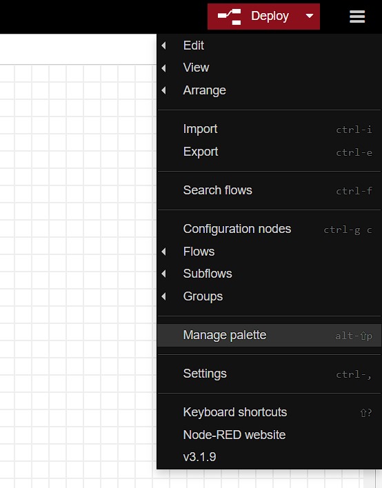
then i installed node-red and run it on my local machine by following quick guide
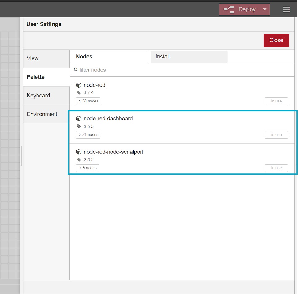
after installing node-red i installed serial and nore-red dashboard pallets using GUI
Node-RED Flow and UI
These were the codes for XIAO_ESP32C3 I used for interfacing
   // LED pin
#define LED_PIN D3

void setup() {
// Initialize Serial Monitor
Serial.begin(115200);

// Set LED pin as output
#include
  #include
  #include

  #define SCREEN_WIDTH  128
  #define SCREEN_HEIGHT 64

  Adafruit_SSD1306 display(SCREEN_WIDTH, SCREEN_HEIGHT, &Wire, -1);

  const int LED = D3;
  String Command="";

  // Variables to keep the current and last state
  volatile int encoderPosCount = 0;
  int lastEncoded = 0;

  void displayMessage(String(message)) {
    display.clearDisplay();
    display.setTextSize(2);
    display.setCursor(2,2);
    display.print(message);
      display.display();


  }

  void setup() {
    Serial.begin(115200);
    Wire.begin();
    if (!display.begin(SSD1306_SWITCHCAPVCC, 0x3C)) {
      Serial.println(F("SSD1306 allocation failed!!"));
      // for (;;);
    } else{
      Serial.println("ready");
    }
    display.setTextColor(WHITE);

    // Set encoder pins as input with pull-up resistors
    pinMode(LED, OUTPUT);
    displayMessage("ready");
  }


  void loop() {
     if (Serial.available() > 0) {
      Command=Serial.readStringUntil('\n');
      Serial.println(Command);
      if(Command == "1" || Command == "0"){
        if(Command == "1"){
          digitalWrite(LED, HIGH);
        }else{
          digitalWrite(LED, LOW);
        }
      }else{
      displayMessage(Command);
      }
     }

  }
Short hero video
blink
files
node-red flow
arduino code