Week 13
Embedded Network & Communication
The group assignment can be found here
This week's assignment was to design, build and connect wired or wireless node(s) with network or bus addresses and a local interface as an individual assignment so i opted for the soil moisture/humidity sensor connected to a quentorres board we made earlier and through it we will display the data collected by the moisture sensor on the LCD display
The soil moisture/humidity sensor working principle is pretty simple and straightforward, as the fork-shaped conductive probe are immersed in theto the soil/water, as the probe has two exposed conductive plates that will act as a variable resistor whose resistance will vary depending on the water content in the soil. This resistance of the probe is inversely proportional to the soil moisture/humidity of the device. The more water the better the conductivity which will result in lower resistance. The less the water the poor the conductivity which means higher resistance. This humidity/moisture sensor produces an output voltage according to the resistance by measuring which we can determine the moisture/humidity level the more water is added, the voltage drops; this is done by passing current through the soil using the two probes, and then it reads that resistance to get the moisture level. More water makes the soil conduct electricity more easily(less resitsance), while dry soil conducts electricity poorly(more resistance). It has four pins VCC, GND, Aout, Dout.
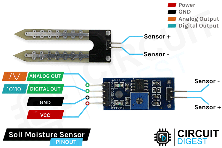
- Vcc: is the power supply pin of the soil moisture sensor that can be connected to 3.3V or 5V of the supply. But do note that the analog output will vary depending upon the provided supply voltage.
- GND: is the ground pin of the board and it should be connected to the ground pin of the Arduino
- DOUT: is the Digital output pin of the board, output low indicates soil moisture is appropriate, and high indicates soil moisture is low.
- AOUT: is the Analog output pin of the board that will give us an analog signal in between vcc and ground.
The entire soil humidity sensor consists of two parts: the first one is the soil moisture sensor probe and the second one is an electronic module. The module processes the incoming data from the probe and that will be processed by the XIAOESP32C3 microcontroller and display the final output on the LCD display. The signal LED on the board turns on when water level increases or humidity levels decreases is added to the soil.
The soil moisture/humidity sensor module is there to convert the incoming analog signal to digital signal; this is designed in such a way that the sensor can be used without microcontroller support. The module consists of two signal input pins where the probe gets connected. It also has four other pins two of which are VCC and GND. The other two are Digital Output and analog Output pins.

This module also consists of a High Precision Comparator, LM393 that is used to digitize the analog signal coming out of the sensor probe. The module has a built-in potentiometer that is used for sensitivity adjustment of the digital output. The main objective of the potentiometer is to set a threshold, so that when the moisture level exceeds the threshold value, the module will output LOW otherwise HIGH.
Display
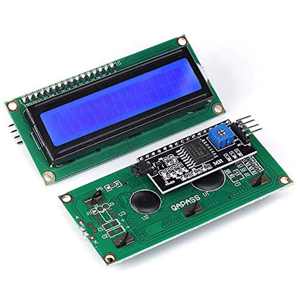
I2C Serial Interface 1602 LCD Module
I was able to find this is the type of LCD in our lab; this I2C interface 16x2 LCD display module, a high-quality 2 line 16 character LCD module with on-board contrast control adjustment, backlight and I2C communication interface. For beginners, no complex LCD driver circuit connection. The real significance advantages of this I2C Serial LCD module will simplify the circuit connection, save some I/O pins on a microcontroller, simplified firmware development with widely available Arduino library. The picture was sourced from here
Brief data
- Compatible with Arduino Board or other controller board with I2C bus.
- Display Type: Negative white on Blue backlight.
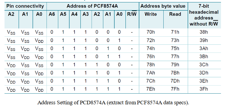
- I2C Address:0x38-0x3F (0x3F default)
- Supply voltage: 5V
- Interface: I2C to 4bits LCD data and control lines.
- Contrast Adjustment: built-in Potentiometer.
- Backlight Control: Firmware or jumper wire.
- Board Size: 80x36 mm
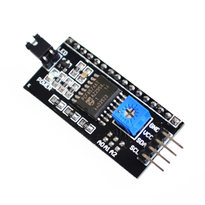
Using the LCD piggy-back board, desired data can be displayed on the LCD through the I2C bus. In principle, such backpacks are built around PCF8574 (from NXP) which is a general purpose bidirectional 8 bit I/O port expander that uses the I2C protocol. The PCF8574 is a silicon CMOS circuit provides general purpose remote I/O expansion (an 8-bit quasi-bidirectional) for most microcontroller families via the two-line bidirectional bus (I2C-bus). Note that most piggy-back modules are centered around PCF8574T (SO16 package of PCF8574 in DIP16 package) with a default slave address of 0x27. If your piggy-back board holds a PCF8574AT chip, then the default slave address will change to 0x3F. In short, if the piggy-back board is based on PCF8574T and the address connections (A0-A1-A2) are not bridged with solder it will have the slave address 0x27.
More info on this can be found here
At first you need to solder the I2C-to-LCD piggy-back board to the 16-pins LCD module. Ensure that the I2C-to-LCD piggy-back board pins are straight and fit in the LCD module, then solder in the first pin while keeping the I2C-to- LCD piggy-back board in the same plane with the LCD module. Once you have finished the soldering work, get four jumper wires and connect the LCD module to your microcontroller as per the instruction given below.
Microcontroller
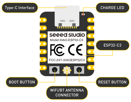
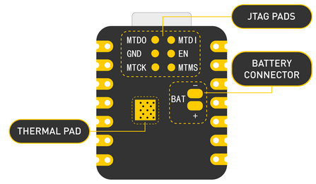
I used the board from the quentorres but i used the XIAOESP32C3 instead of using rp2040 that was used initially in the quentorres due to its availability on the local market, eventhough the patterns behind Xiaos are different i managed to use it and it worked perfectly. So as a notice, the bottom of the XIAOESP32C3 has pins for JTAG Pads, Battery connnector, Thermal Pads so to avoid the short circuit that could happen, you can use insulation tape behind your Xiao to prevent short circuits, you can solder the XIAO pins higher to avoid these pins on the back to touch the copper plate.
Short hero video
Short hero video
Assignment Files