Week 3
MOLDING AND CASTING
Group Assignment
The group assignment link can be found here
DESIGNING
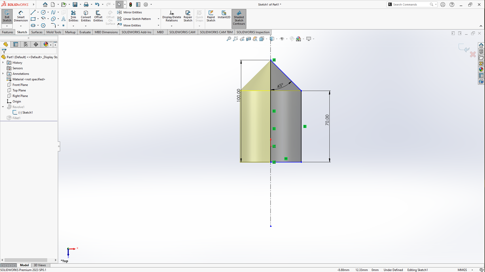
I started by designing using solidworks to make the parts of the mold that were to be 3D milled on cnc, i chooose solidworks due to the fact that i've been used to using now so it was a much faster easier choice than picking any other CAD. i opened the software went to parts-Top plane-sketch, then went on sketching the design for this model which is portrayed in the picture below.
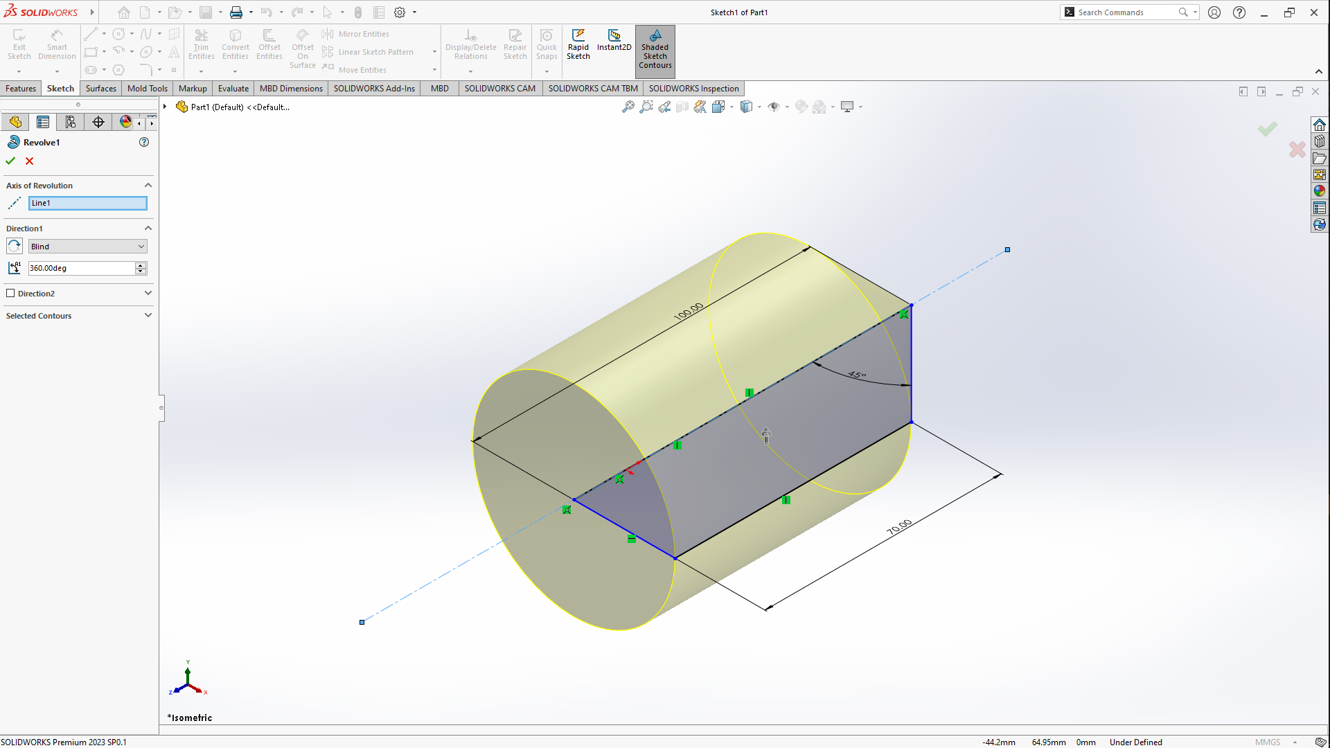
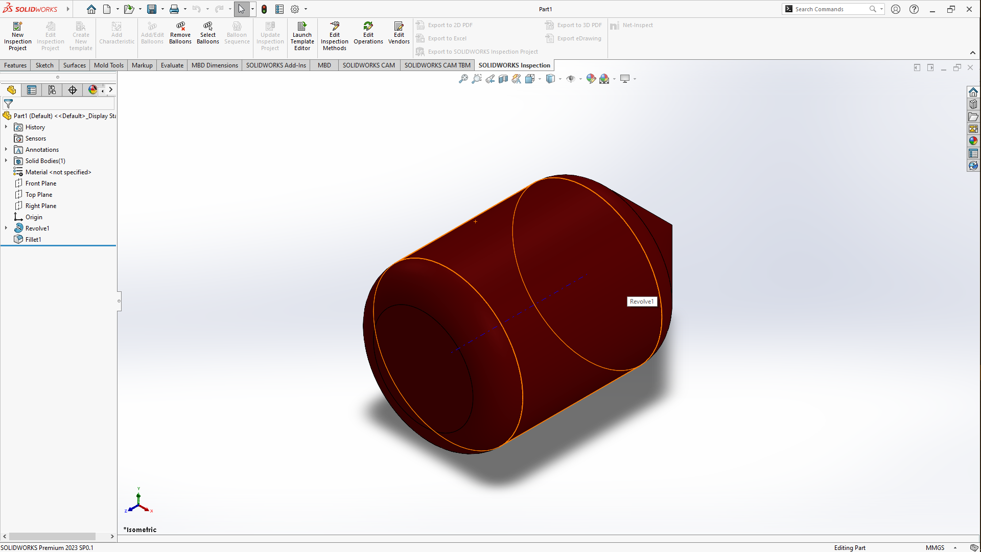
After finishing the sketch i went to add feature by going in the top left corner and click on features then click on revolve boss/base this opens up a window then under axis of revolution i selected the middle dashed line as the axis of revolution then i clicked on ok to close off the revolve panel then i added offset on the bevels.
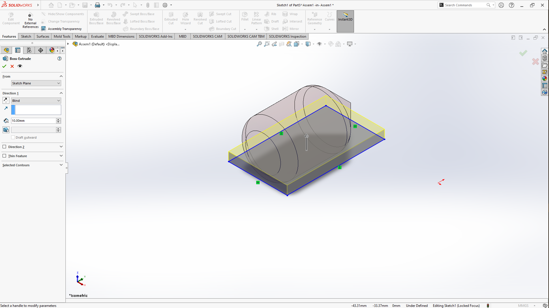
After that i went up to the menu bar clicked on the drop down menu on new scrolled down to Make assembly from Part/Assembly which opened up a window then you drag the part from it and then drop it in the workspace, now in the new window open, you go up in the menu bar and then click on assembly-insert components, clicked on its drop down menu then clicked on New Part then selected the Top plane-then right click on the top planethen normal to then i draw a rectaangle on the top plane, added dimensions then clicked on features then clicked on Extrude boss/base extruded it to 4CM or 4MM, then clicked to close the panel next I clicked on Insert then features then cavity with its panel Open, under cavity, there's a design components block, click on it then after head to the left of this panel where its written assembly then tap the drop down menu and then tap what's named pattern 1 or which ever name you had given it beforehand then click ok, you can add color too too be able to differentiate it with the other part that we will be designning
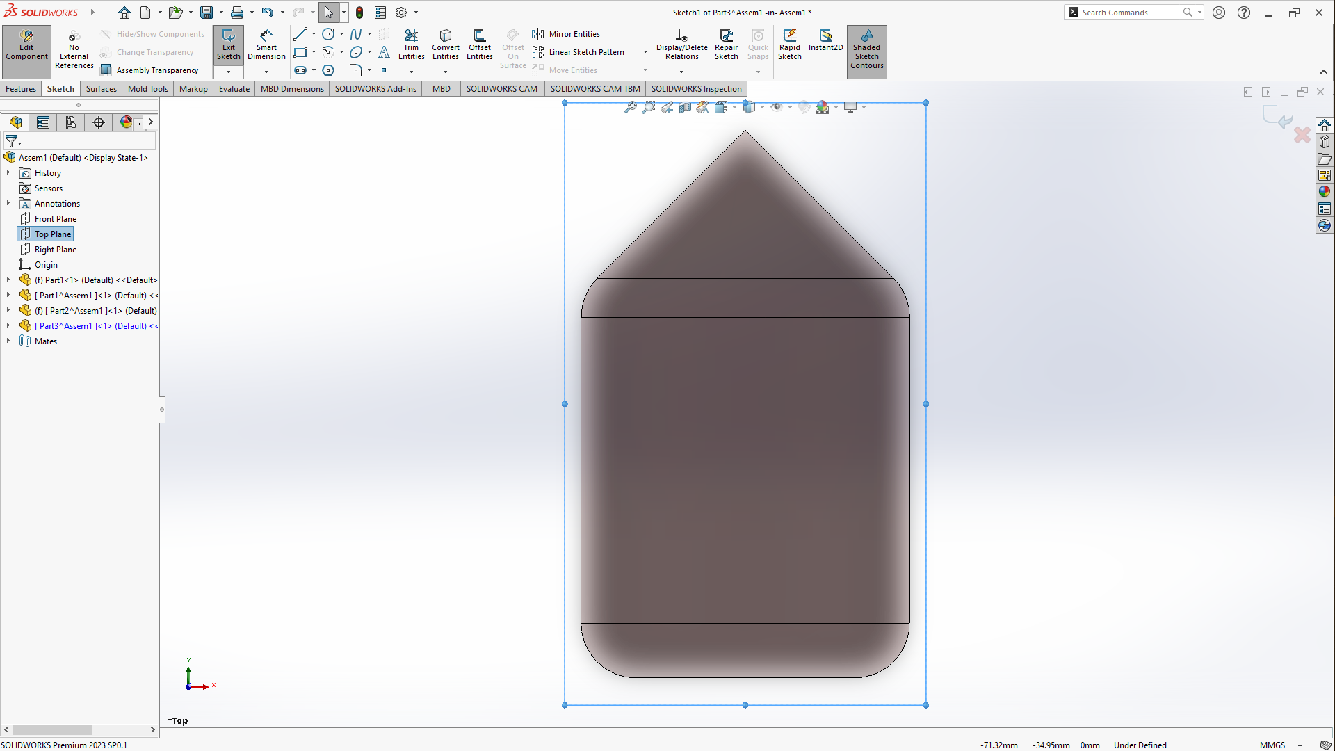
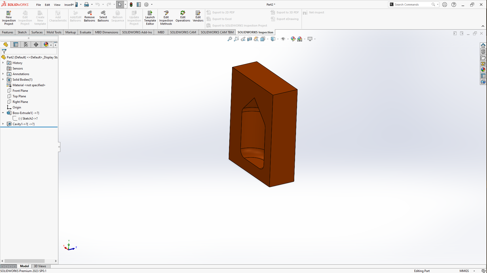
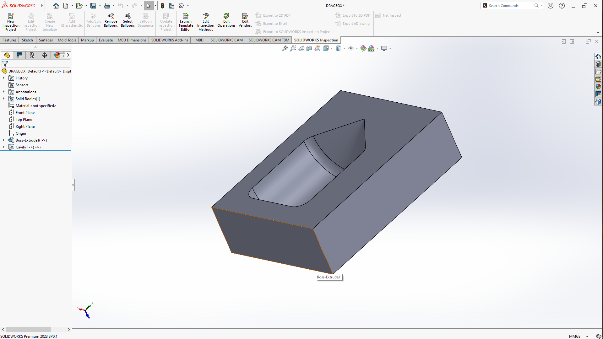
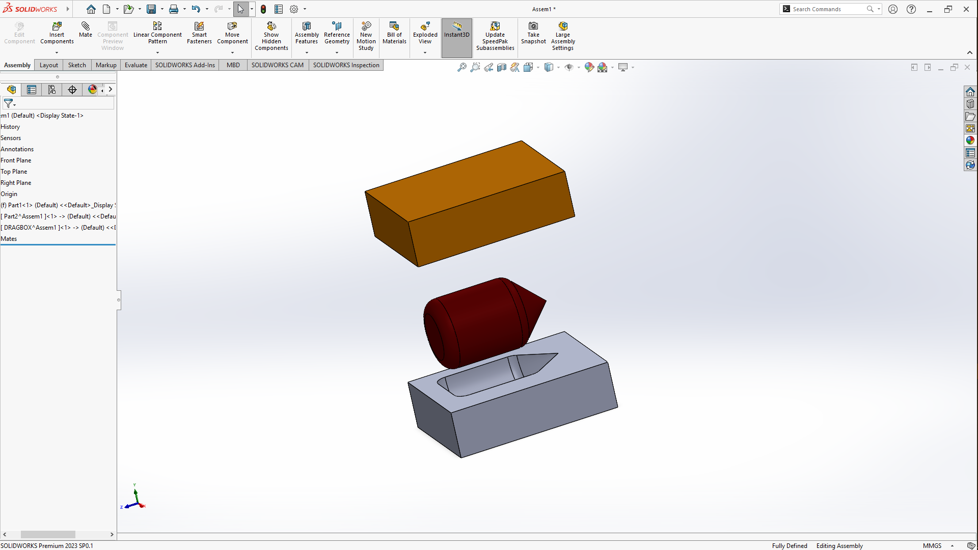
The other part can be drawn by using the process going to Insert components-New Part , select the front face of the model we just extruded, set to Normal to- draw a rectangle that fits that has the same size as the other part we extruded, then Exit sketch- Extrude boss to 40MM/40CM. After extruding, go to Insert - Features - cavity in design components select pattern 1 click ok and give it a color too and rename it then exit feature. Next in the commands manager, click on Explode View - select the top part pull it upward then select then the lower part and pull it downwards.
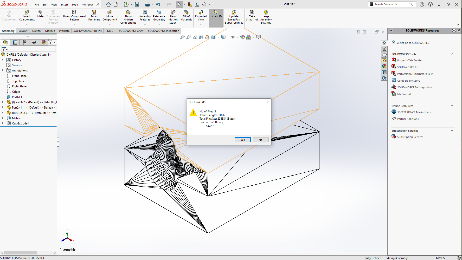
Saving the stl file
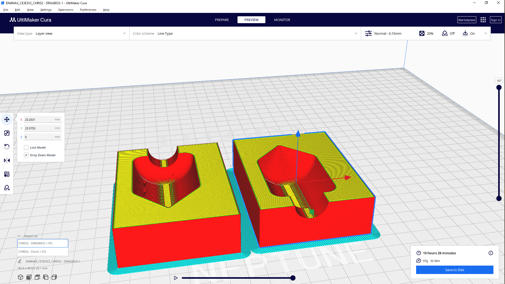
Slicing
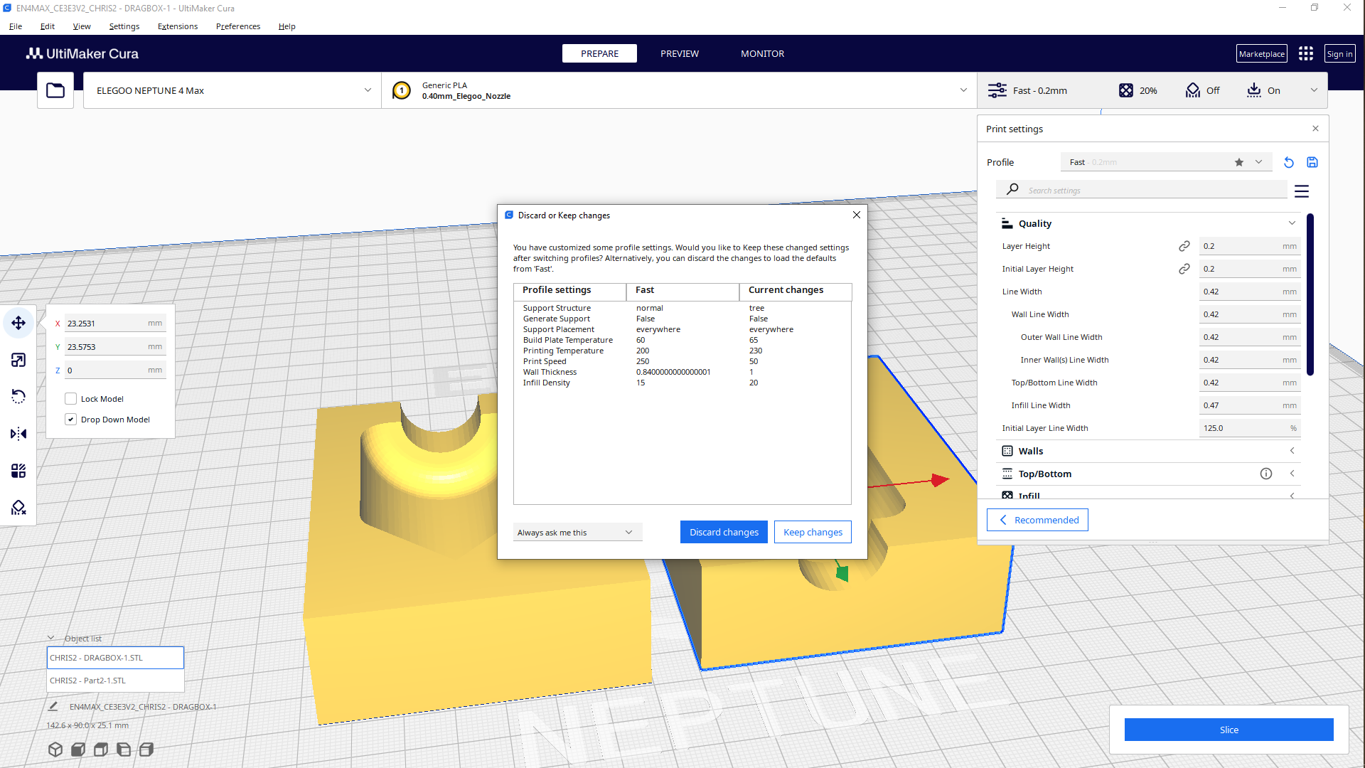
Settings
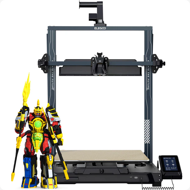
I used a different printer to other assignment, here i used ELEGOO nepturne 4 Max
The output of the files i printed
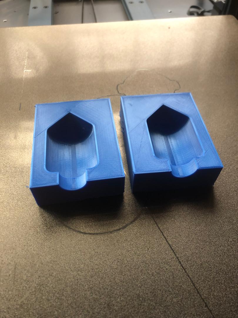
Group wise, due to deadline issues i understood from my colleagues that it was okay to do this reason why i did this, now taking the same route as my colleagues i proceeded with sanding the inside of of the printed parts to make it smooth enough to compare the two
After i used the sand paper on the inside surface of the model to smoothen it to have a better output diferent than the first
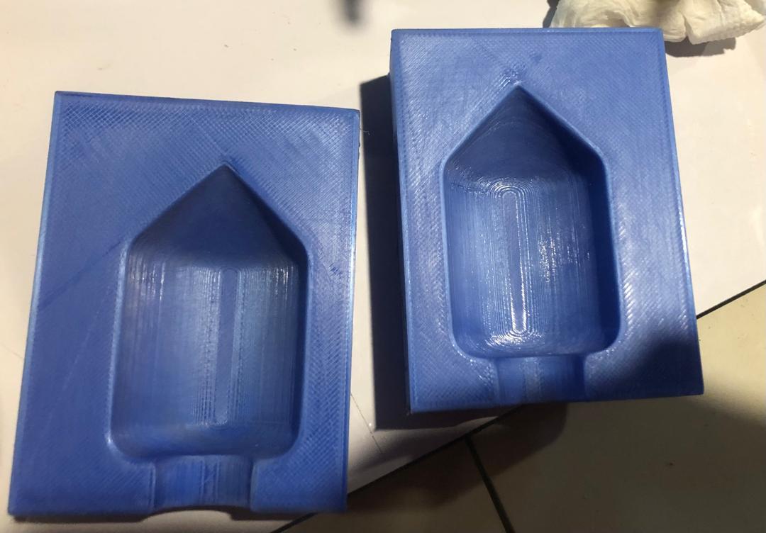
On this one the surface looks polished due to having used the sand paper on the interior of the mold
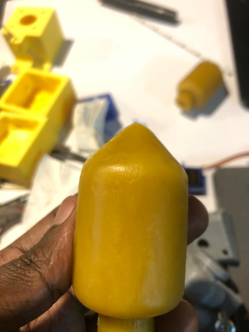
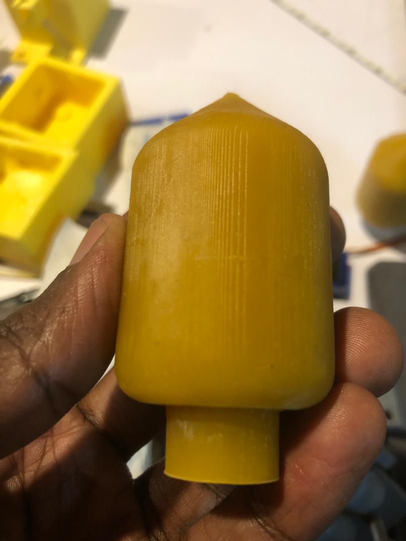
When looking at these too models i realised that the model on the left has a smoother surface due to polishing the inside of the of the mold, which is the difference with the picture on the right because we poured the hot mold directly in the mold after being 3D PRINTED; which is why it has some kind of lines on the surface which shows the roughness. so for better output its necessary to sand the mold before pulling the liquid in it.
Assignment Files