Wildcard Week
This week is like a free pass to try out whatever we want. We can design and make almost anything using digital tools like computer-aided design and manufacturing. I decided to focus on working with metal because I haven't had much experience with metal tools and machines before.
Things I experimented this week:
1. Metal lase Cutting
2. Metal Etching
Metal Laser Cutting
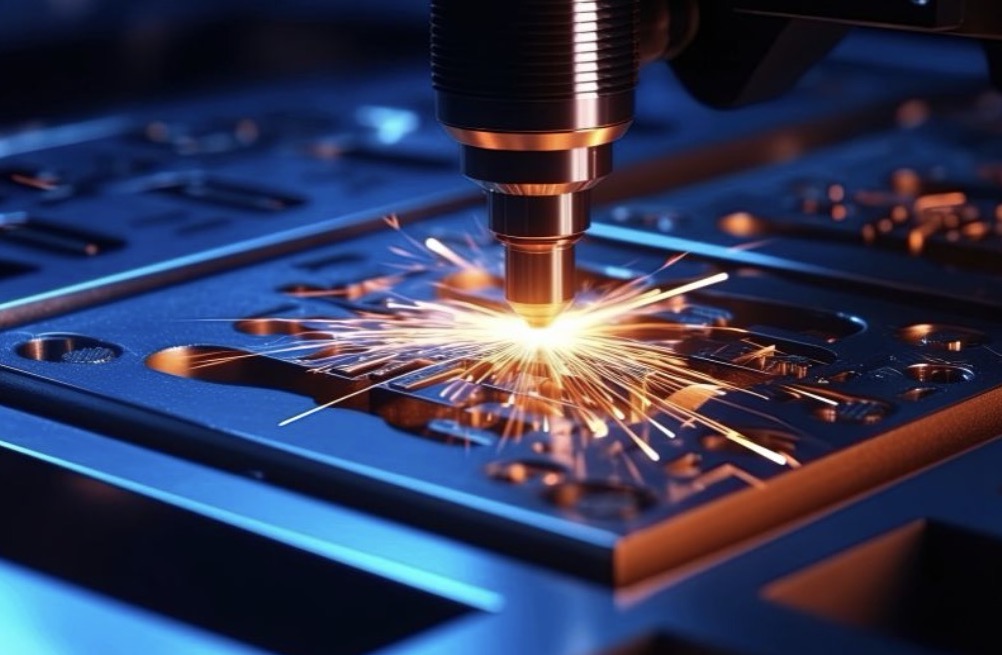
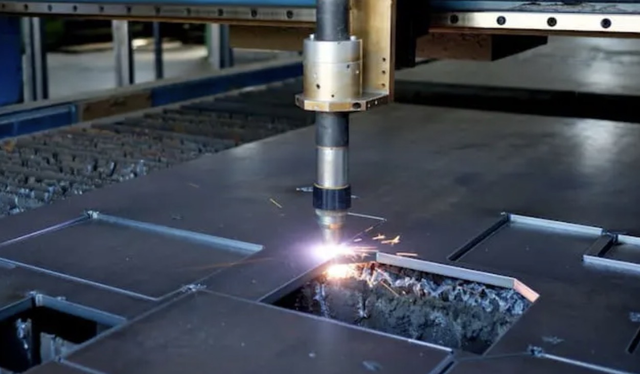
Metal laser cutting is a process where a high-powered laser beam is used to cut through metal sheets or plates with precision. The laser beam is directed onto the metal surface, melting or vaporizing the material along the cutting path. This technology allows for intricate and accurate cuts, making it suitable for various applications in industries such as automotive, aerospace, and manufacturing.
We don't have metal machines in house so we sourced it from the local vendor from outside.
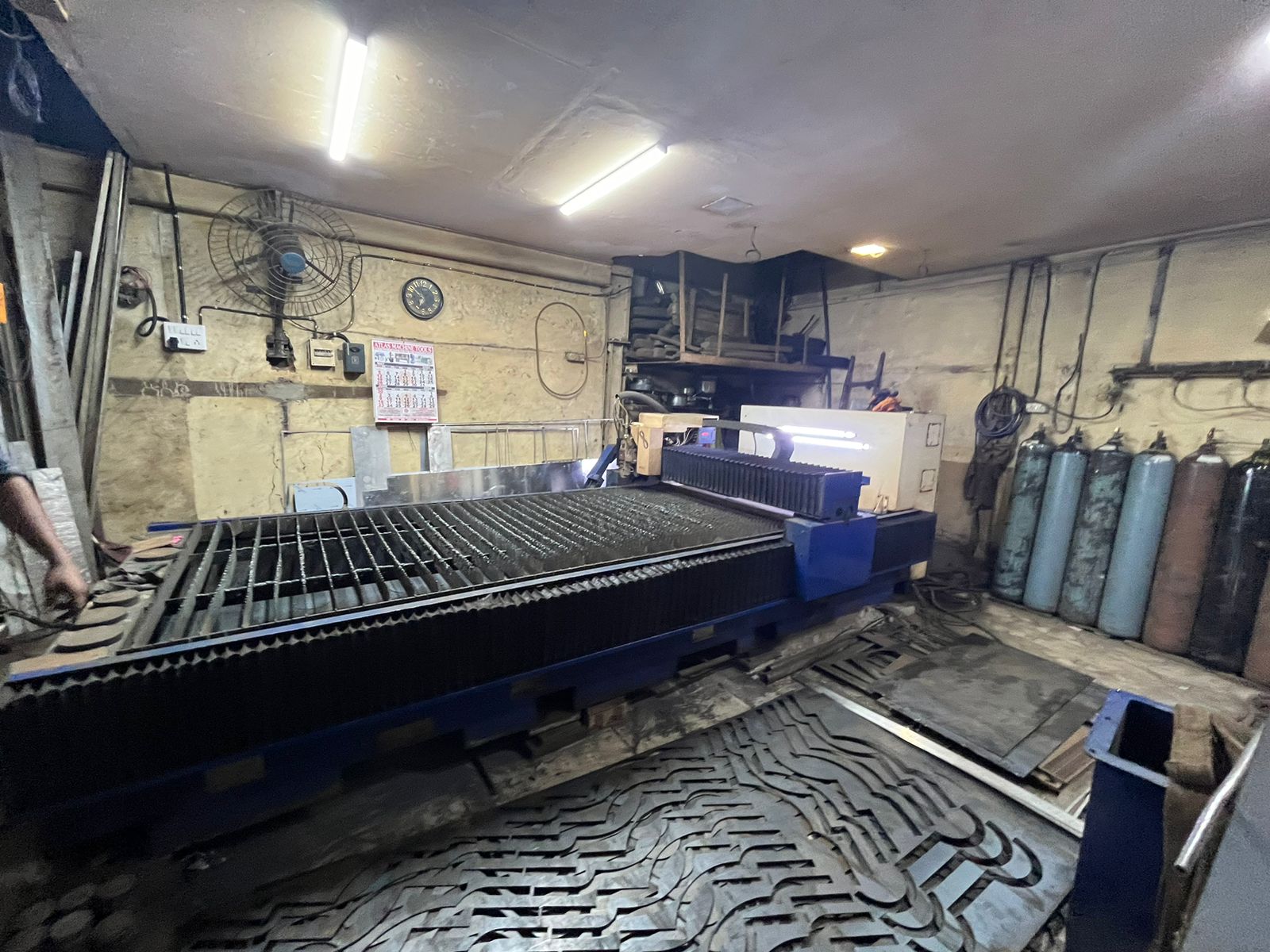
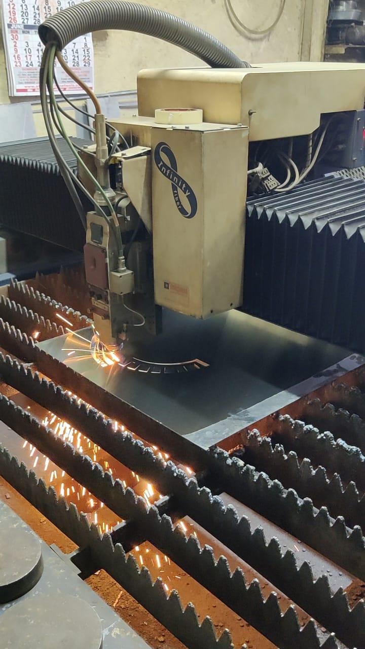
Metal laser cutting machine
This was the machine which was at the workshop and we used this machine.
Difference between different metal cutting machine
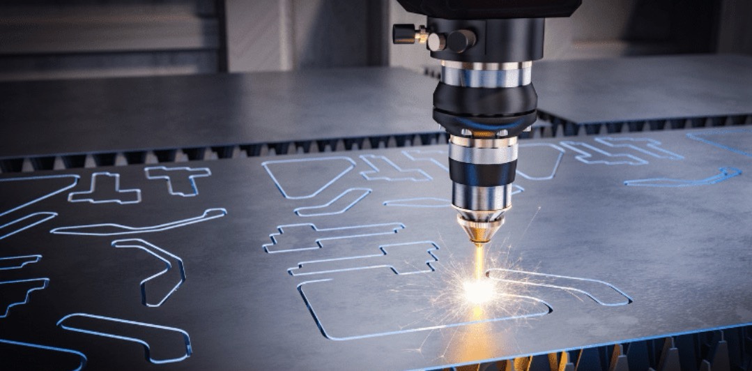
1. Laser Cutting Machine:
Utilizes a high-powered laser beam to cut through metal sheets or plates. Offers high precision and versatility, capable of cutting intricate designs and patterns. Suitable for a wide range of metals, including steel, stainless steel, aluminum, brass, and copper. Can produce clean, burr-free edges with minimal material waste. Generally faster than traditional cutting methods and allows for automation.
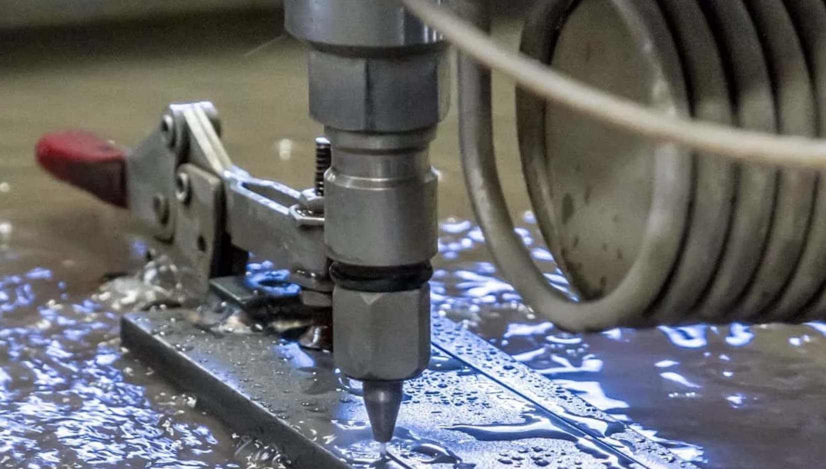
2. Waterjet Cutting Machine:
Uses a high-pressure stream of water mixed with abrasive particles to cut through metal. Ideal for cutting thick materials or materials sensitive to heat, such as titanium, stone, and glass. Does not generate heat-affected zones (HAZ) and minimizes the risk of material distortion or warping. Can cut through reflective or non-conductive materials without the need for special adjustments. Offers excellent precision and can produce intricate shapes and contours.
3. Plasma Cutting Machine:
Utilizes a high-temperature plasma arc to melt and cut through metal. Suitable for cutting conductive metals such as steel, stainless steel, aluminum, and copper. Offers high cutting speeds and is particularly effective for thick materials. Generates heat-affected zones (HAZ) along the cut edges, which may require additional post-processing. Typically used for industrial applications requiring high productivity and cost-effective cutting.
4. CNC Milling Machine:
Employs rotating cutting tools to remove material from a solid metal workpiece. Capable of milling complex shapes, contours, and features with high precision. Suitable for a wide range of metals, including steel, aluminum, brass, and titanium. Offers versatility for both roughing and finishing operations, such as drilling, tapping, and contouring. Can accommodate various tooling configurations and cutting strategies for optimal efficiency.
Metal Compatibity
Different metals respond differently to laser cutting. Factors such as material composition, thickness, and surface finish can affect the cutting process and the quality of the final cut. Understanding the properties of the metal being cut is crucial for achieving optimal results.
Material Thickness
In stainless steel (SS) we can cut from 0.5mm to 8mm thick material
In mild steel (MS) we can cut from 0.5mm to 16mm thick material.
Characterisation
Metal kerf = 0.2 mm
Nozzle changes according to the material
Spacing between 2 piece is 5mm.
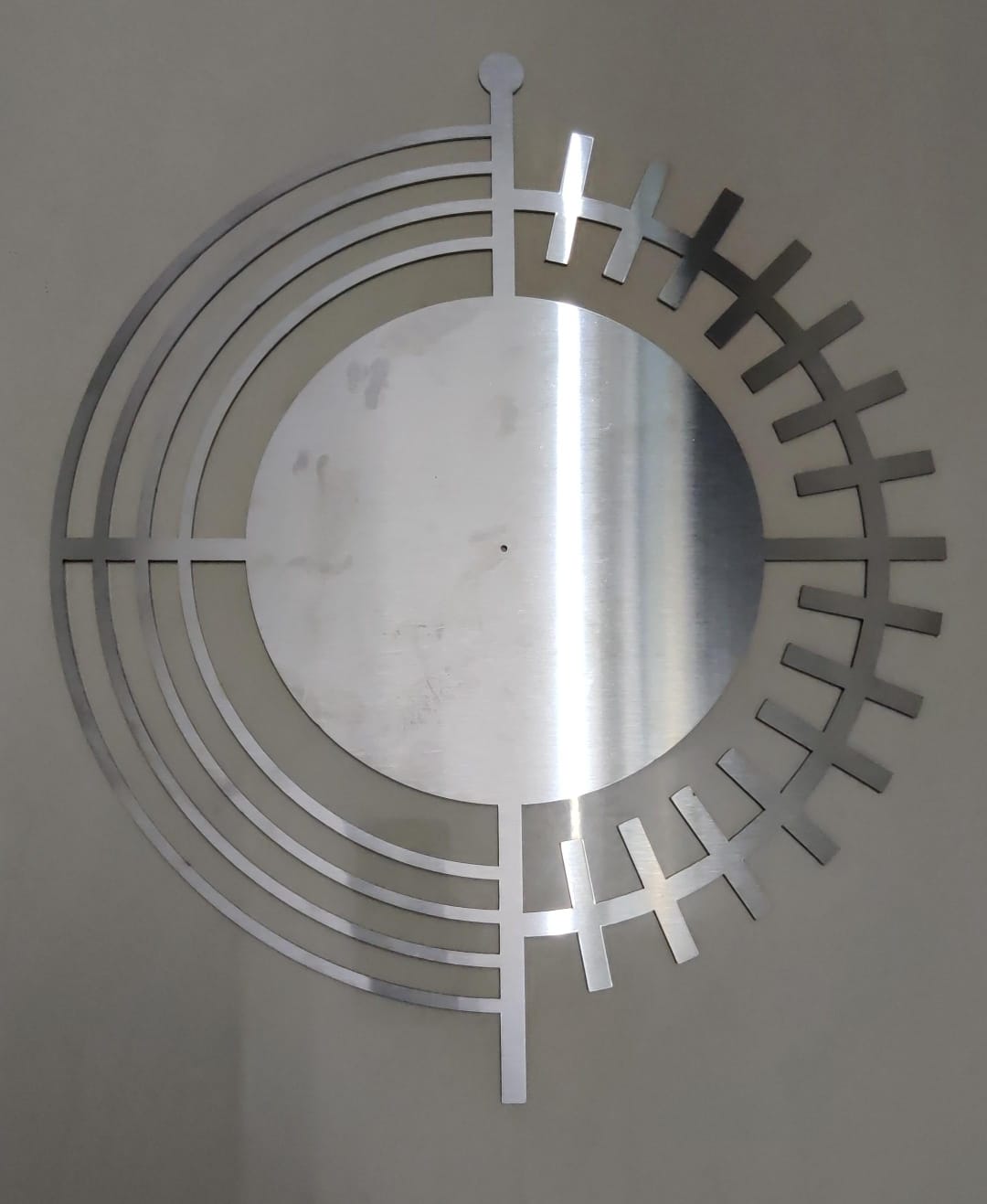
I made a wall clock for my home from metal, below is the image of my wall clock design.I designed it on illustrator below is the image of the design.
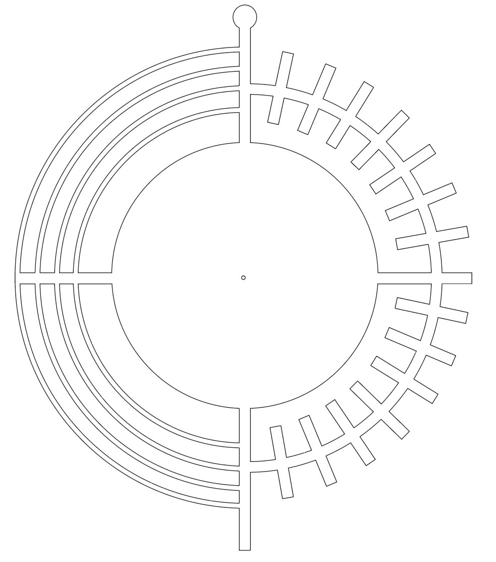
As the walls were very thin ( 5mm ), so I decided to use metal laser cutting and not waterjet cutting.
Toolpath
For making the toolpath we used cypcut software which is similar to rdworks software of laser cutting but with more features and parameters of cutting.
Steps to Use CypCut Software for Metal Laser Cutting
Initial Setup:
a. Power On: Turn on the laser cutting machine and the connected computer with CypCut software.
b. Connect: Ensure the computer is connected to the laser cutter via the appropriate interface (USB, Ethernet, etc.).
Import Design File:
a. Open CypCut software.
b. Import your design file (usually in .dxf or .svg format).
Material and Machine Settings:
a. Material Selection: Choose the type of metal you are cutting (e.g., steel, aluminum).
b. Thickness: Enter the thickness of the material.
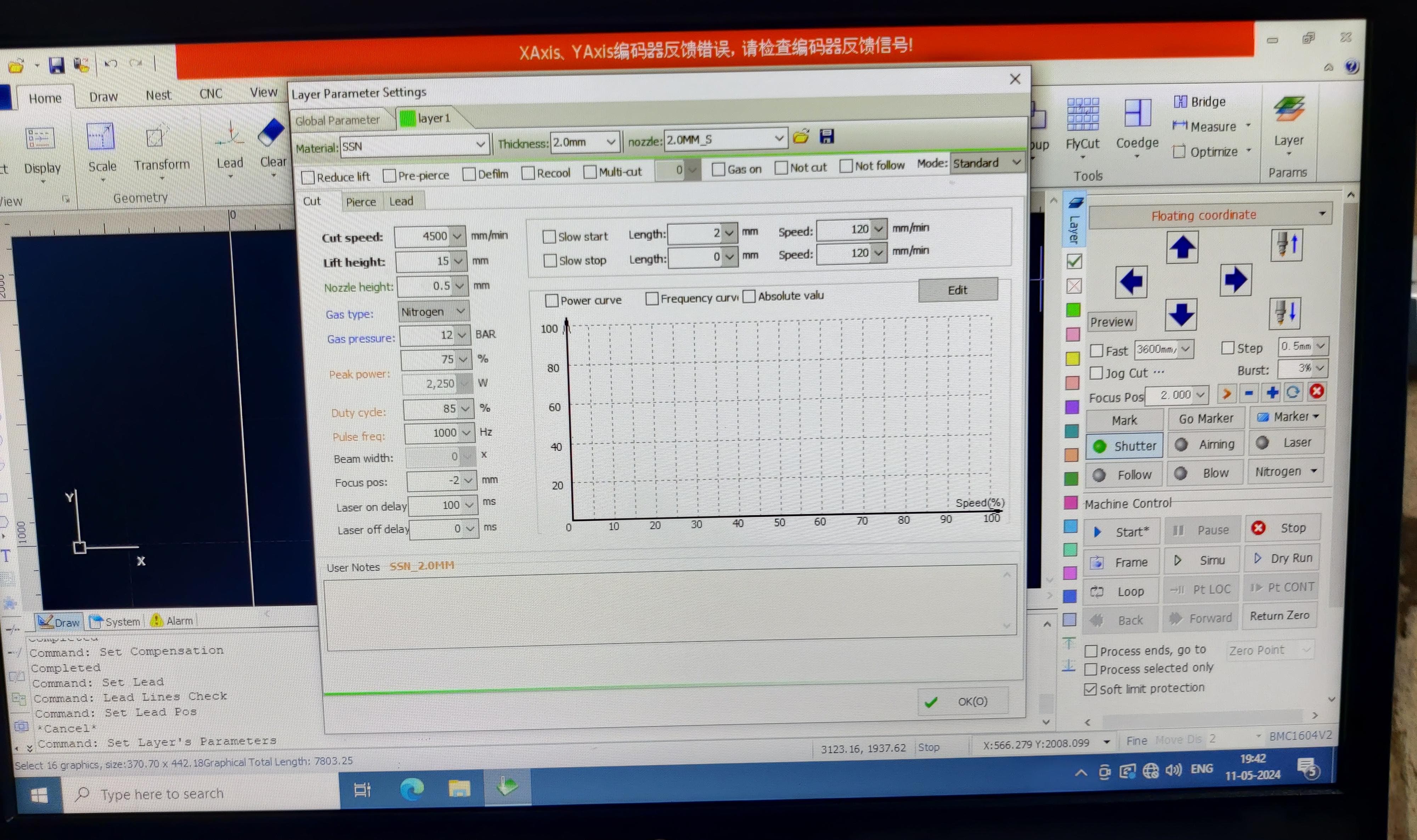
c. Cutting Parameters: Set the laser power, cutting speed, and gas pressure based on the material and thickness.
I found two aspects particularly intriguing here: the speed is adjusted typically as we do with our standard laser cutter, but the power is determined by the percentage of gas supplied and the type of gas utilized. There are two types of gases employed for laser power. Firstly, Oxygen tends to leave behind a black residue on the material and yields lower quality cuts. On the other hand, Nitrogen doesn't leave any residue and produces high-quality cuts. I've included a snapshot below detailing the cut settings.
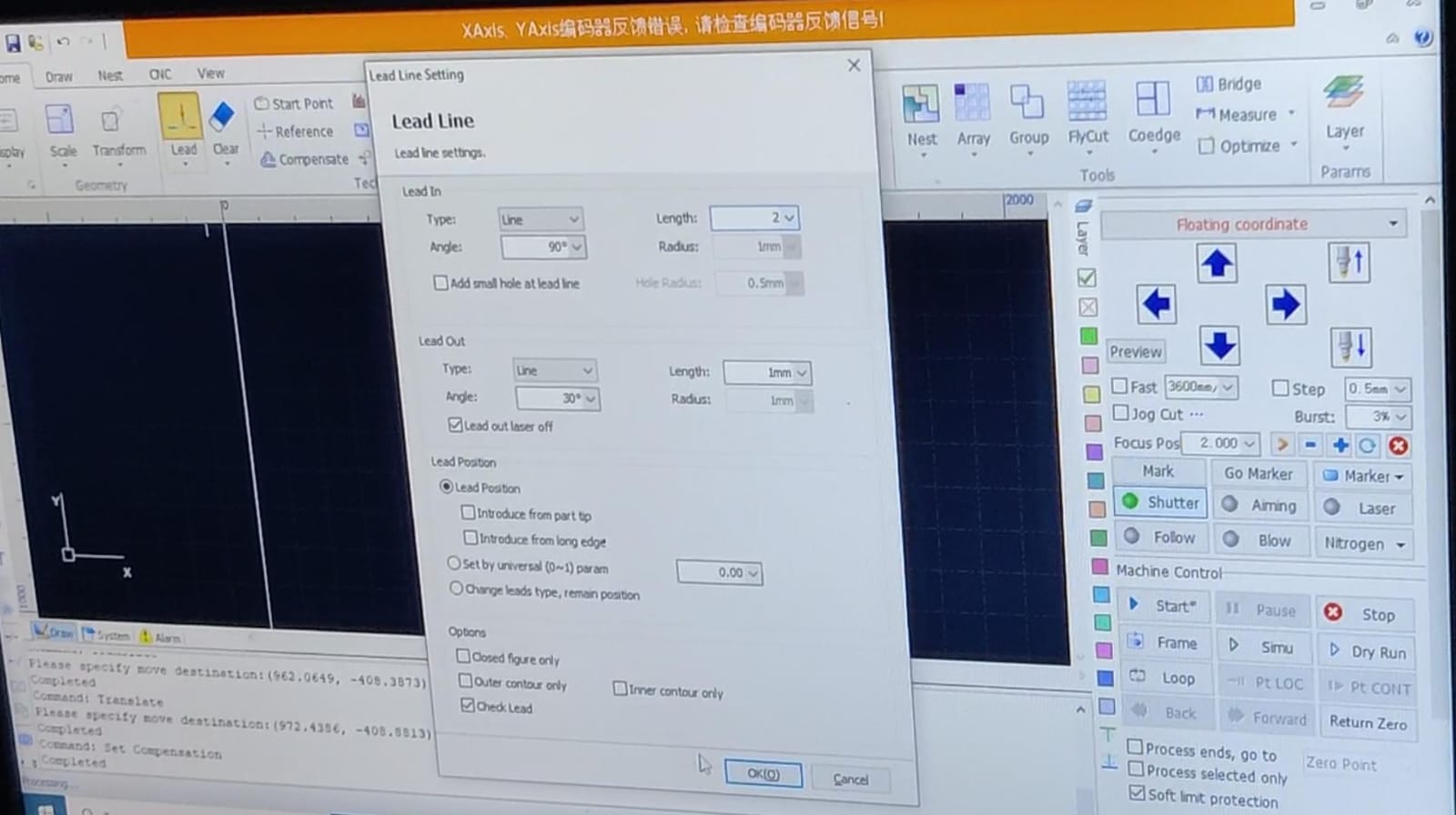
Lead Line Settings:
a. Open Lead Line Settings: Navigate to the lead line settings tab in CypCut.
b. Lead-In:
1. Type: Select the type (straight or arc).
2. Length: Set the length to ensure the laser reaches full power before cutting the actual part.
3. Angle: (If applicable) Set the angle for straight lead-ins.
c. Lead-Out:
1. Type: Select the type (straight or arc).
2. Length: Set the length to ensure a smooth finish.
3. Angle: (If applicable) Set the angle for straight lead-outs.
4. Position: Ensure lead-ins and lead-outs start and end outside the main cutting area.
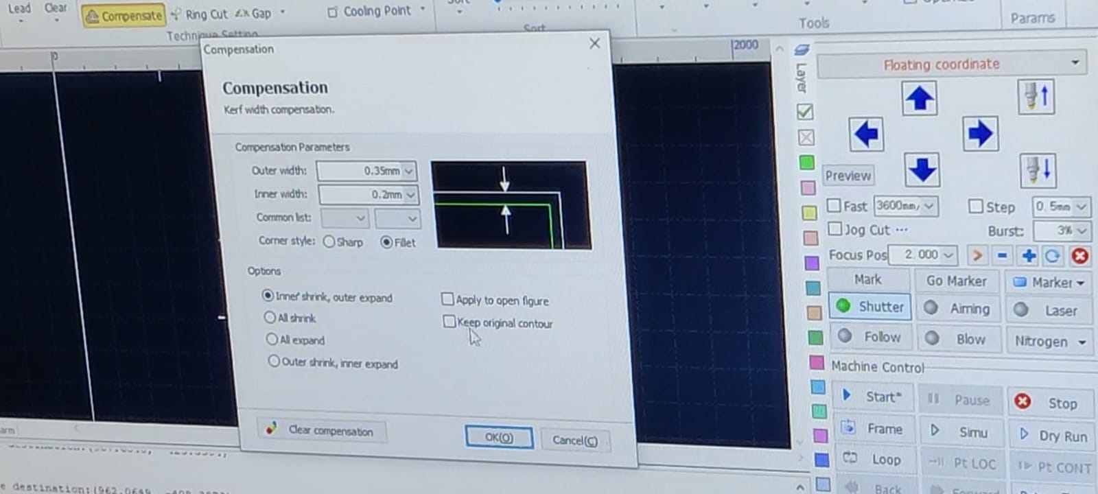
Compensation Settings:
a. Open Compensation Settings: Navigate to the compensation settings tab.
b. Kerf Width:
1. Kerf Value: Input the kerf width (width of material removed by the laser).
2. Compensation Direction: Choose internal (negative kerf) for inside cuts and external (positive kerf) for outside cuts.
c. Offset Settings: Apply necessary offsets to ensure accurate final dimensions.
d. Automatic vs. Manual: Decide between automatic (software-calculated) or manual compensation settings.
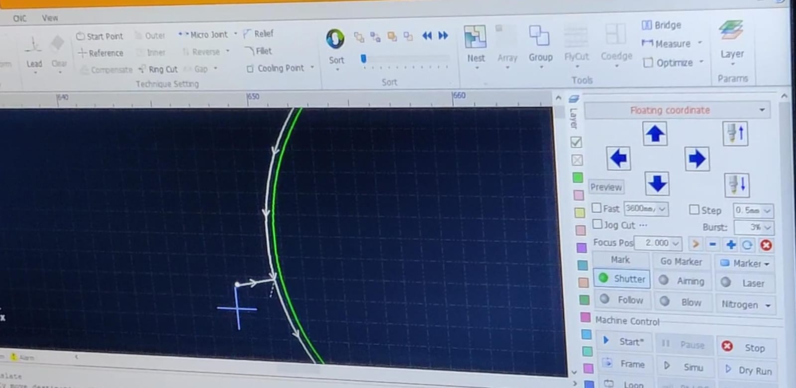
Additional Settings:
a. Lead Line and Compensation Verification: Check that lead lines and compensation settings are applied correctly to all cutting paths.
b. Simulation: Run a simulation in CypCut to verify the toolpath, ensuring the lead lines and compensation settings are correct.
Generate Toolpath:
Generate the toolpath and export it as a cutting program file (.nc or .cnc).
Transfer to Machine:
Copy the toolpath file to a USB drive and insert it into the laser cutting machine's controller.
Machine Setup:
a. Insert Toolpath File: Select the file from the machine's controller.
b. Set Speed and Feed: Input the cutting speed and feed rate based on the material and thickness.
c. Set Origin:
1. XY Origin: Align the XY origin to the corner of the bed or the reference point used in the toolpath file.
2. Z Origin: Use the paper method to set the Z origin:
a. Lower the router until the tool's tip touches the stock.
b. Raise it slightly and insert a thin piece of paper underneath.
c. Adjust the Z height until there is just enough friction between the tool and paper.
Start Cutting:
a. Ensure all safety protocols are in place (e.g., wearing safety glasses, securing the material).
b. Start the cutting process from the machine's controller.
c. Monitor the process to ensure it runs smoothly.
To see the detailed video of how to make toolpath, click below:
Cutting Process
I used stainless steel of 2mm, so according to the material we changed the nozzle, this is how the the nozzle of metal laser cutting looks:
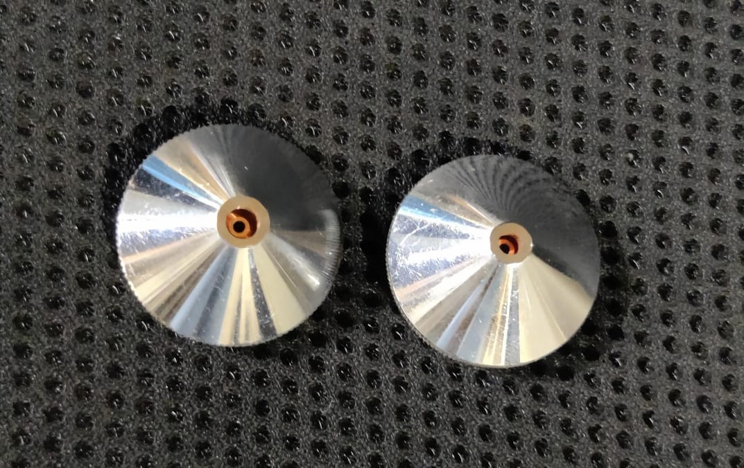
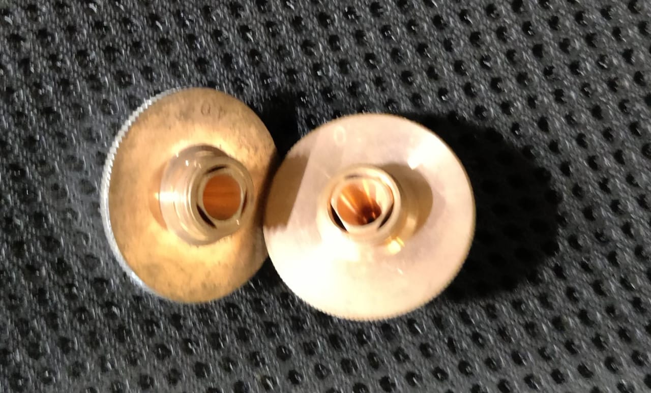
After changing the nozzle we adjusted the origing and checked the frame for cutting and then the cutting started
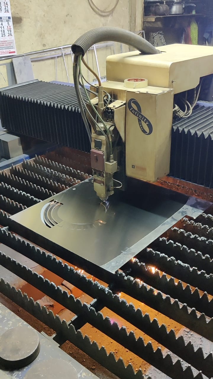
After cutting
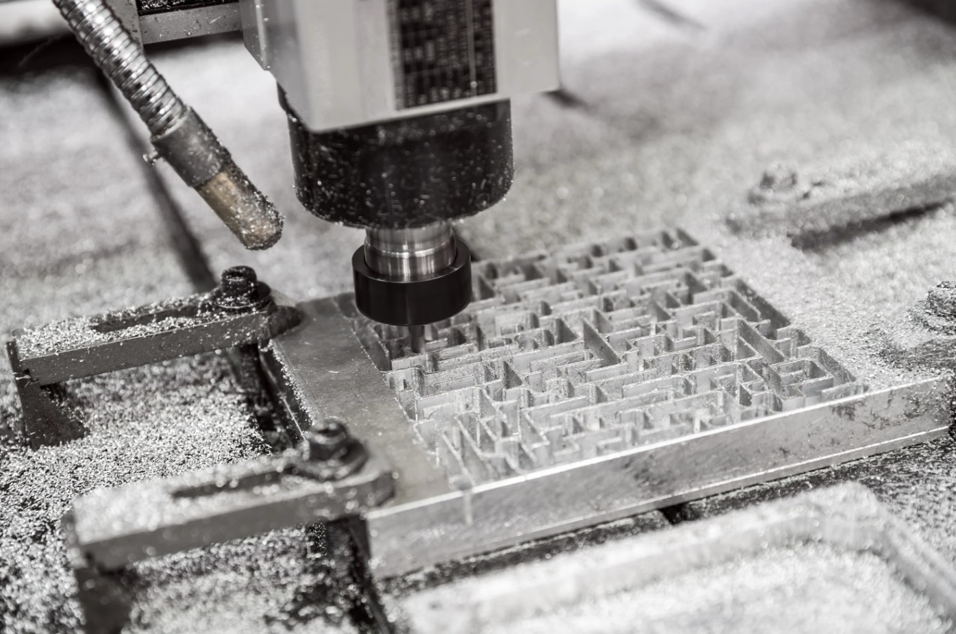
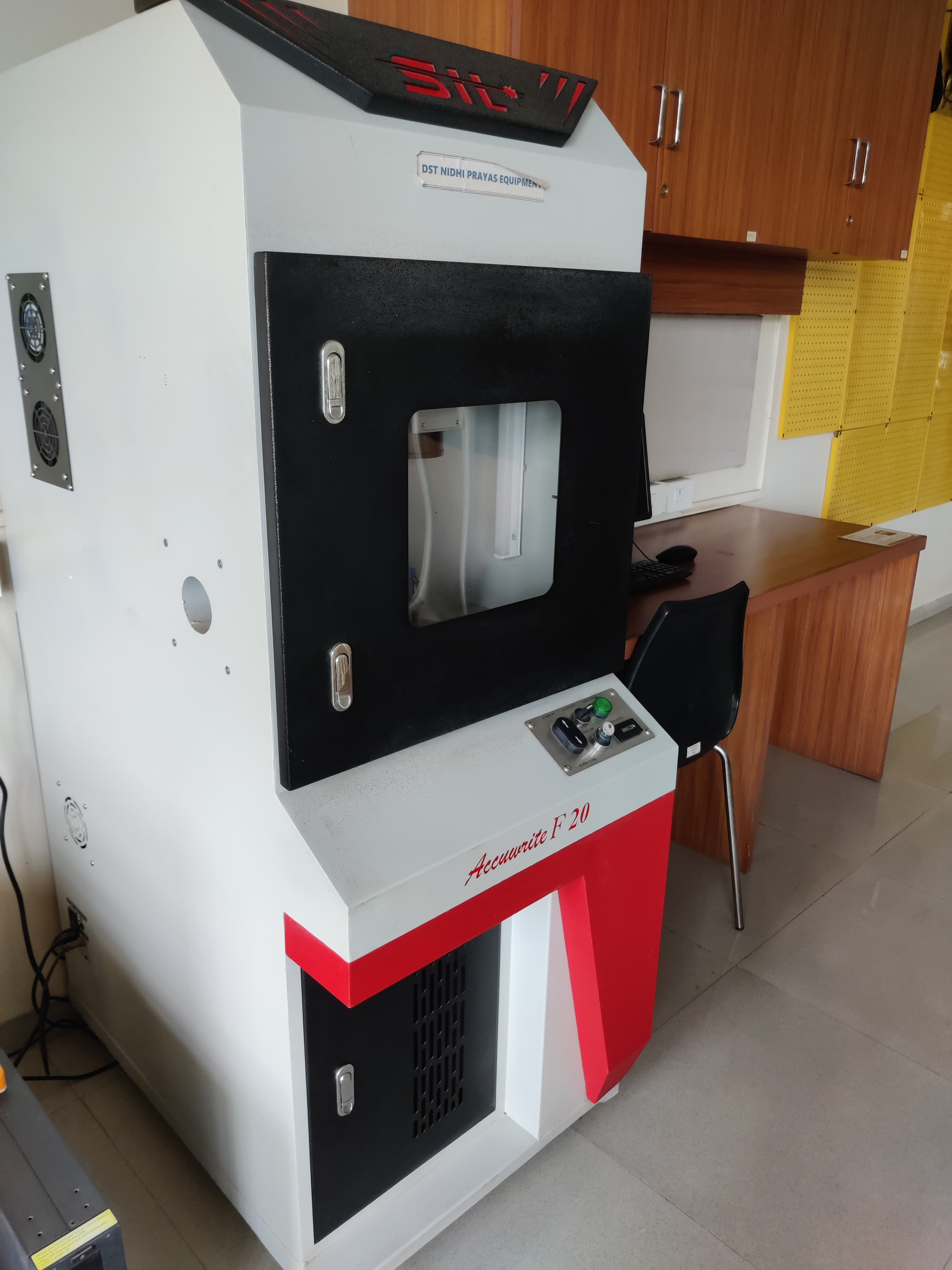
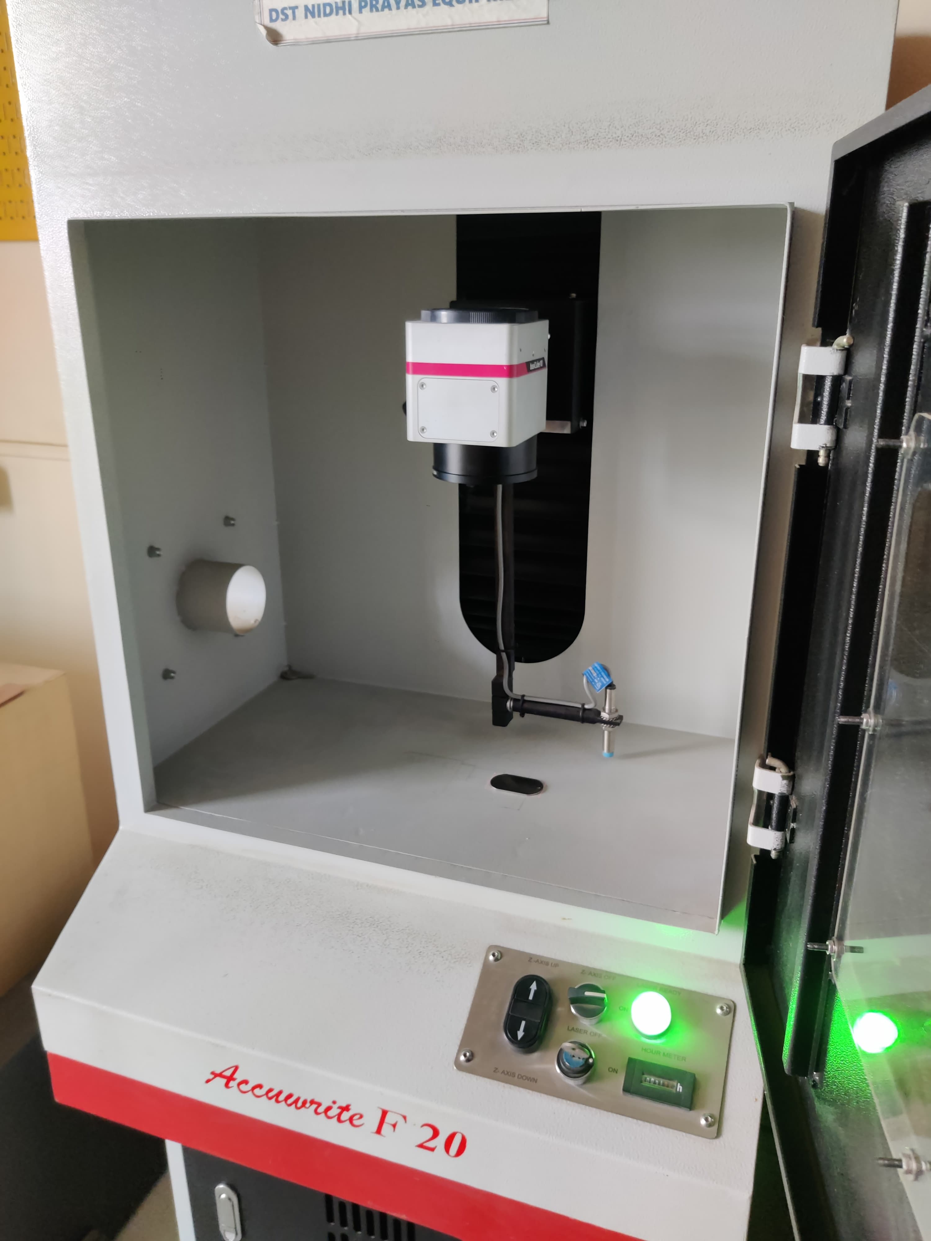
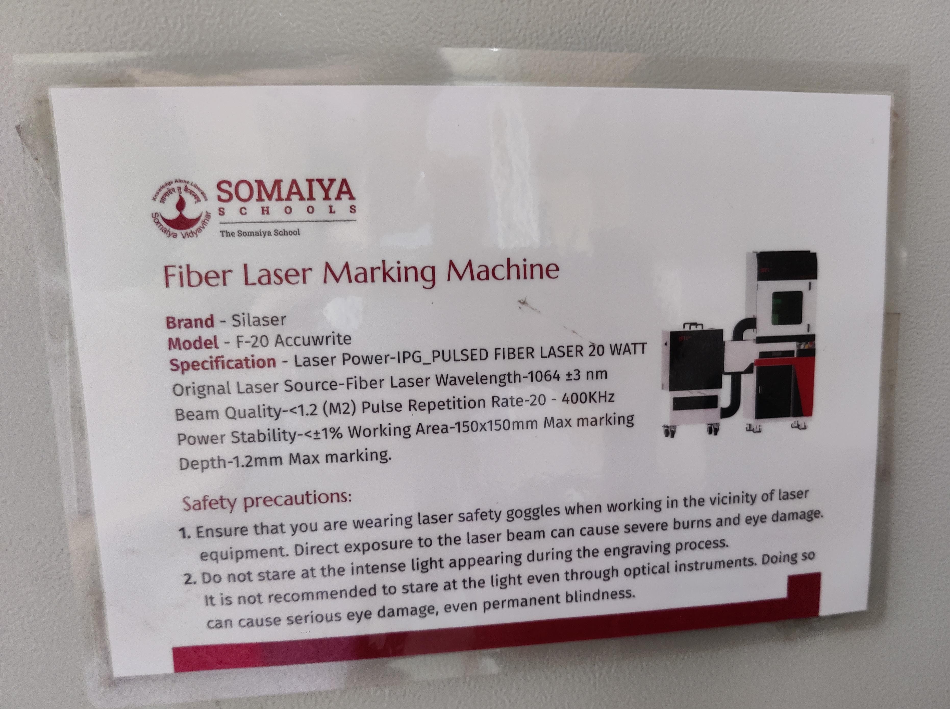
Metal Etching
We had waste metal pieces left so we tried doing metal etching on that piece.
This is how the machine looks:
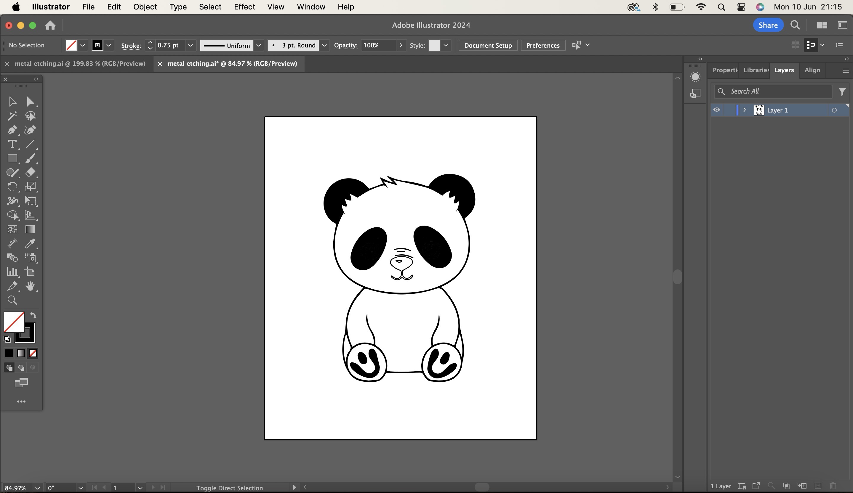
Design
First step is to make a design of the file, I made it in illustrator the design is shown in the image below.
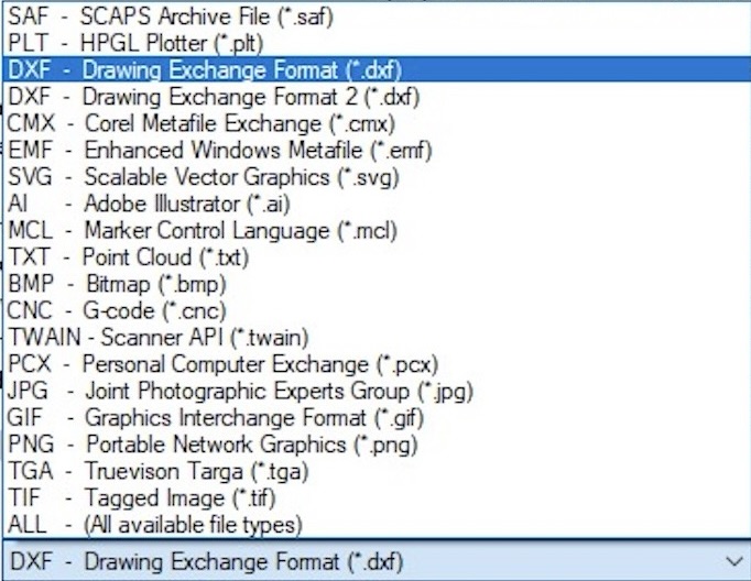
After making the design export the designs in the formats given below in the image, I exported it in dxf format.
Toolpath
To start we need to make a toolpath of this file after the design is ready, we made the toolpath in SAM-light software.
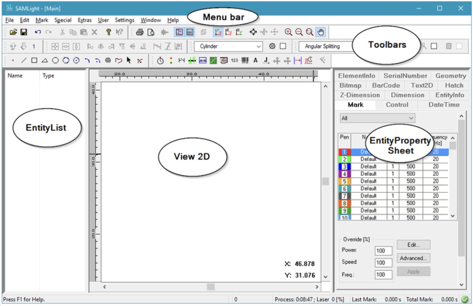
This is how the interface of the sam light softwares look like.
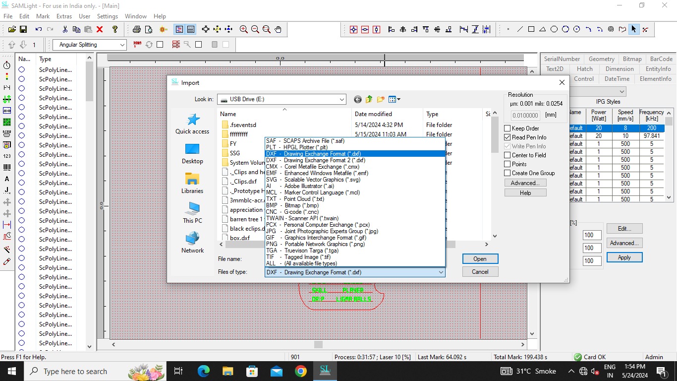
At the start select in which format you are going to upload the file, I selected dxf format as I have exported the file in dxf format from illustrator.
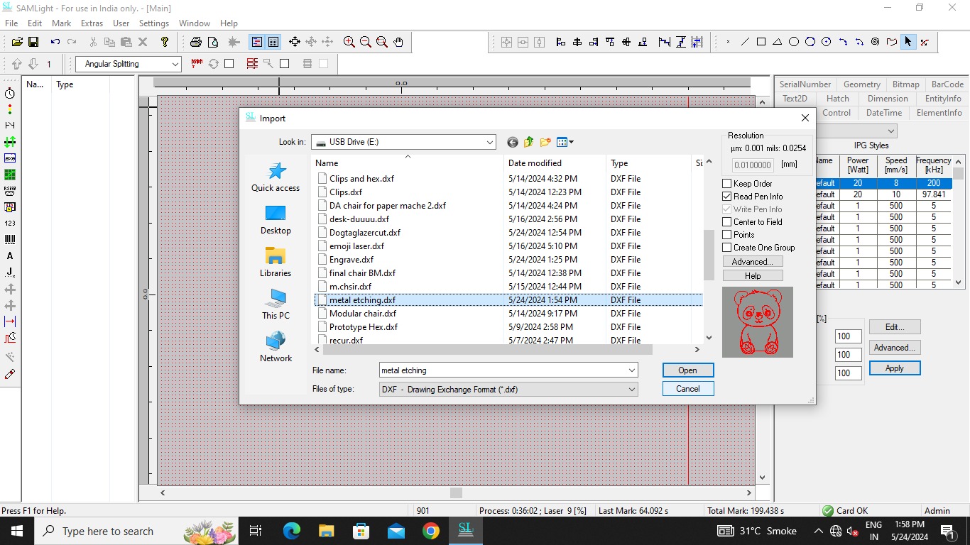
After that select your file and open it in the software.
After opening the file you will see the file like this as shown in the image below, put the object in the box.

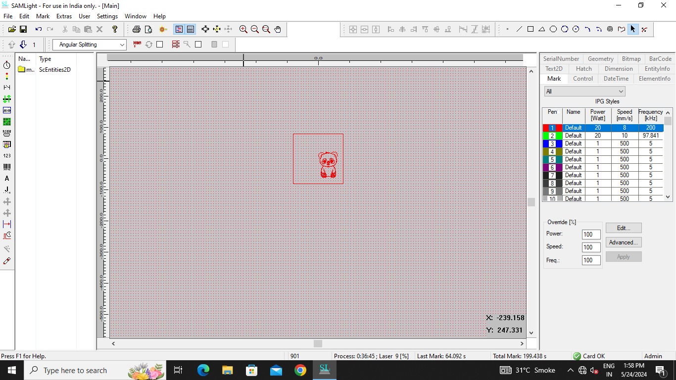
Change the measurements of your object according to the size of metal piece you have, I had a waste metal piece of 9 by 5cm so I used that piece only and adjusted it according to that.
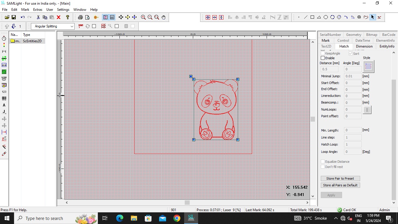
Then go in control and select that you want to hatch or only engrave and select hatch type from control panel.
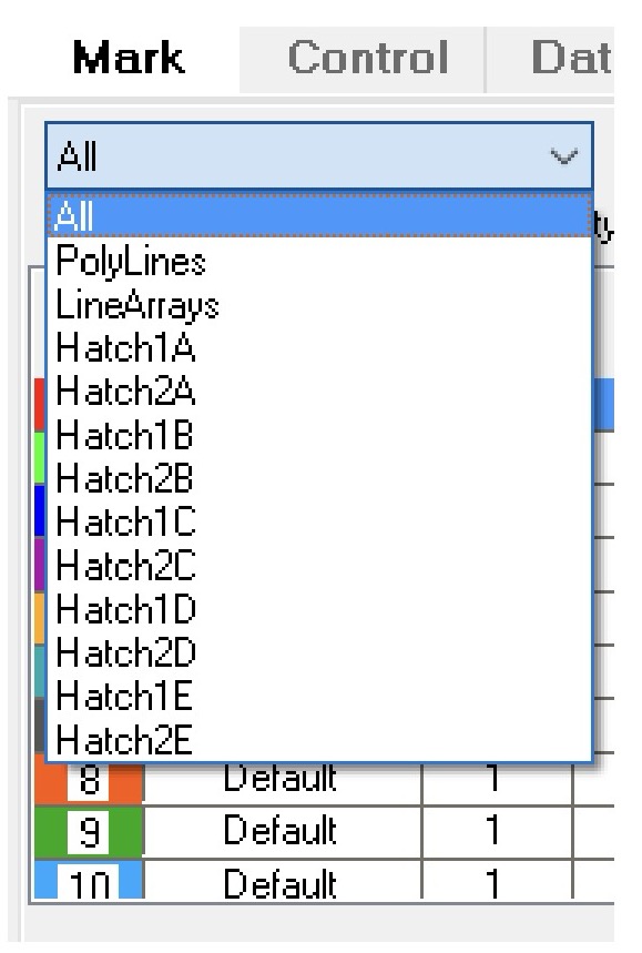
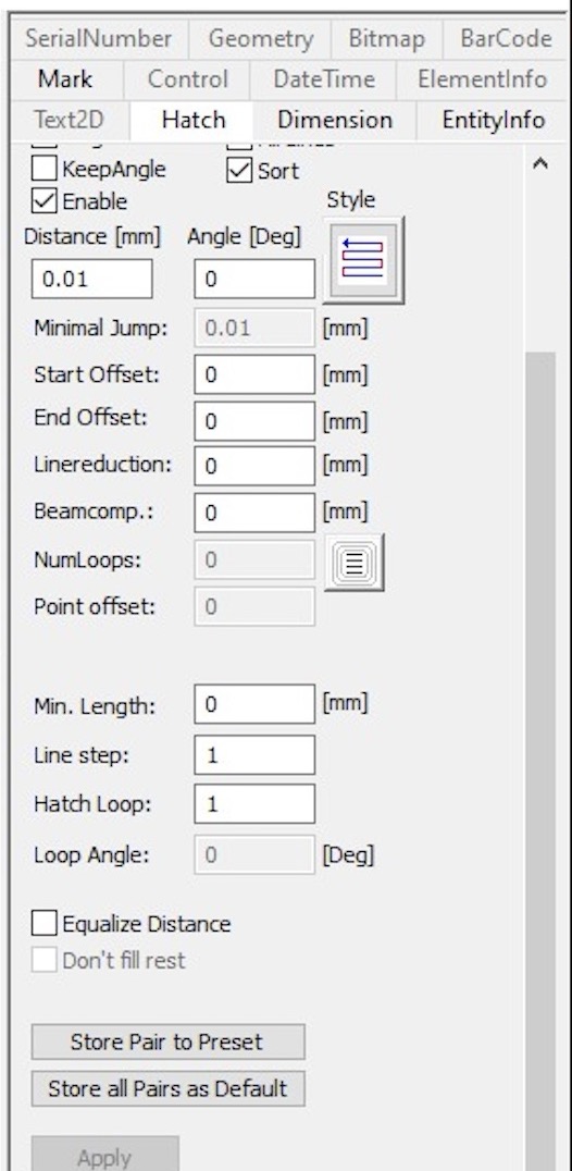
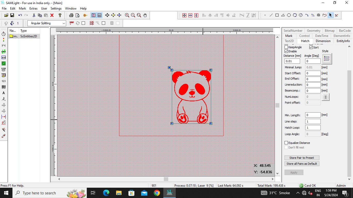
After that you will be able to see the object, the black part in the onject is going to be hatched.
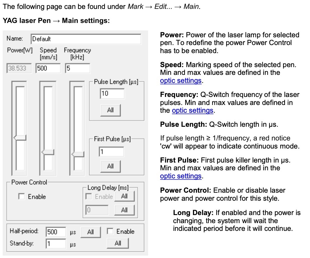
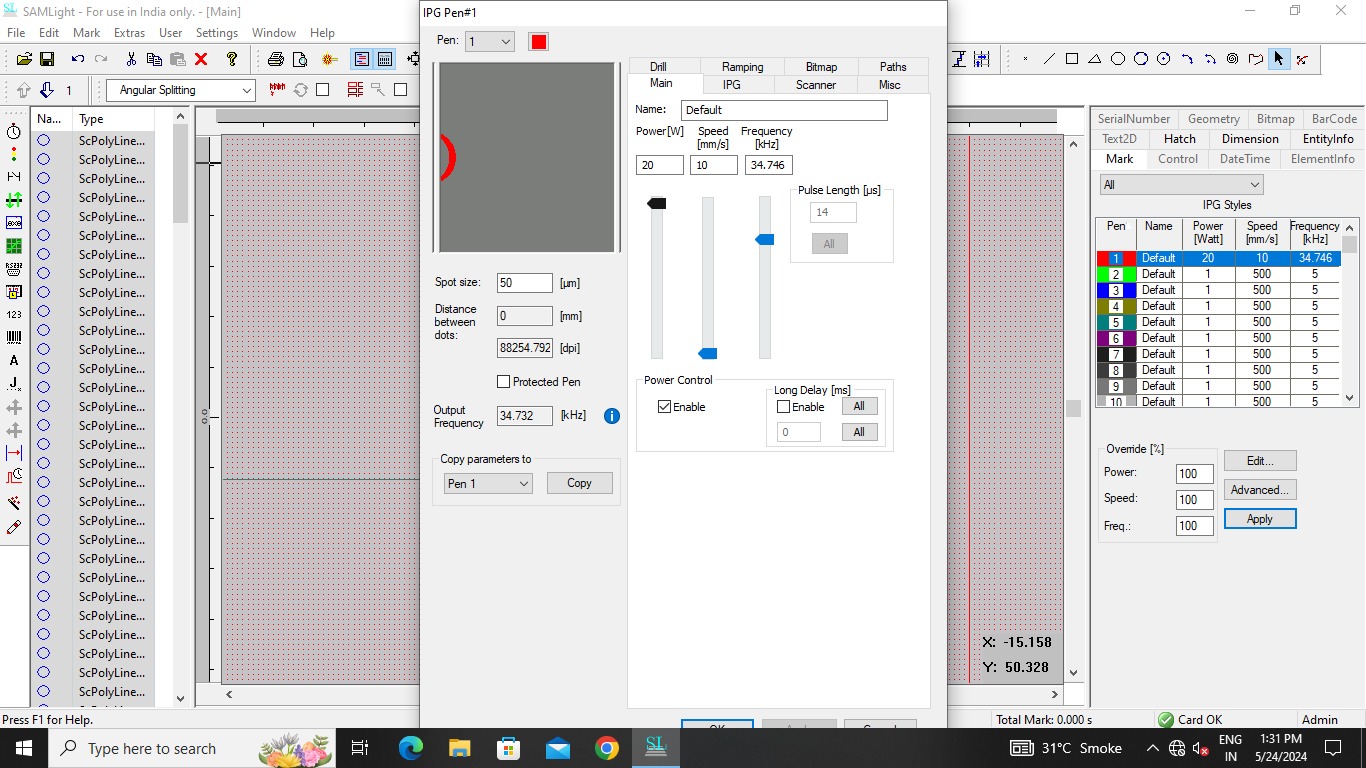
Go in IPG styles in right panel and when you click a window of speed and power will open, here I saw a new thing called frequency. Frequency is the min and max of laser pulses which is going to come.More details is explained in the image below and even my speed powere of the file is shown below.
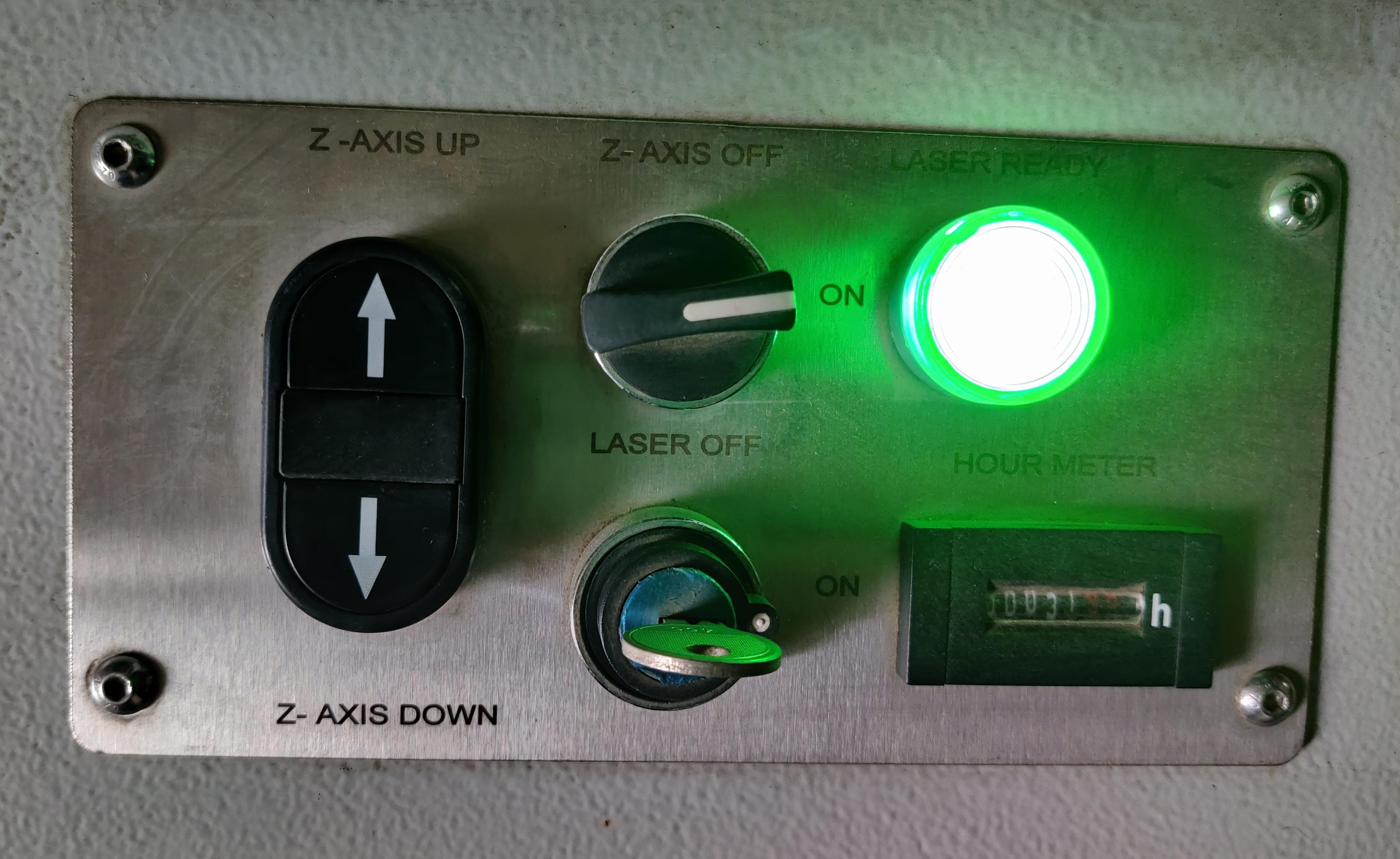
Go on the machine and there is a controller of the machine.Turn on the laser and you can adjust the Z-axis manually from here or from the software whatever is comfortable.
Then go in mark option in right panel and tick total outline and enable, it will show you the red light on the piece which helps you to understand where will the object be hatched and you can change the posistion and size accordingly.Remember to start the machine or else you will not be able to see the red light.
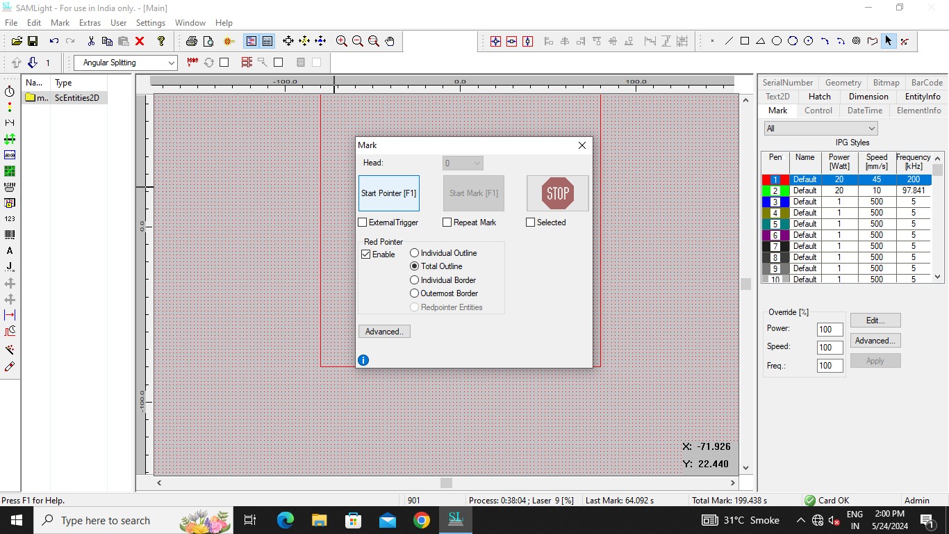
After this press on start mark and the machine will start running. But before doing anything you need to read the safety instructions at start when you enter the workshop.
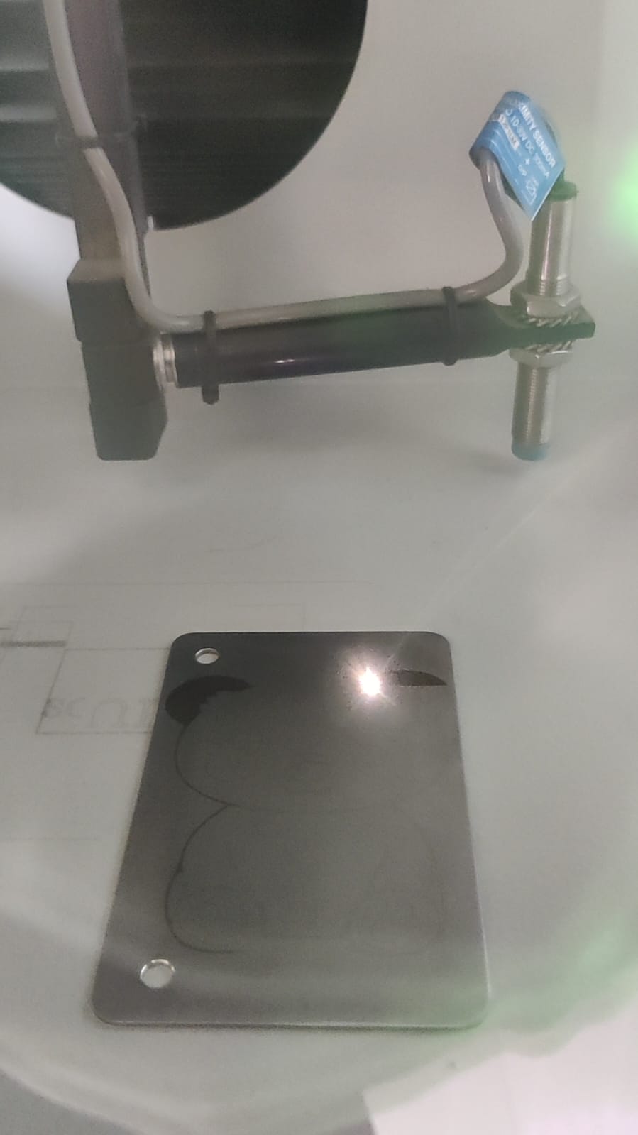
Below are the images and videos of how the machine does hatching.
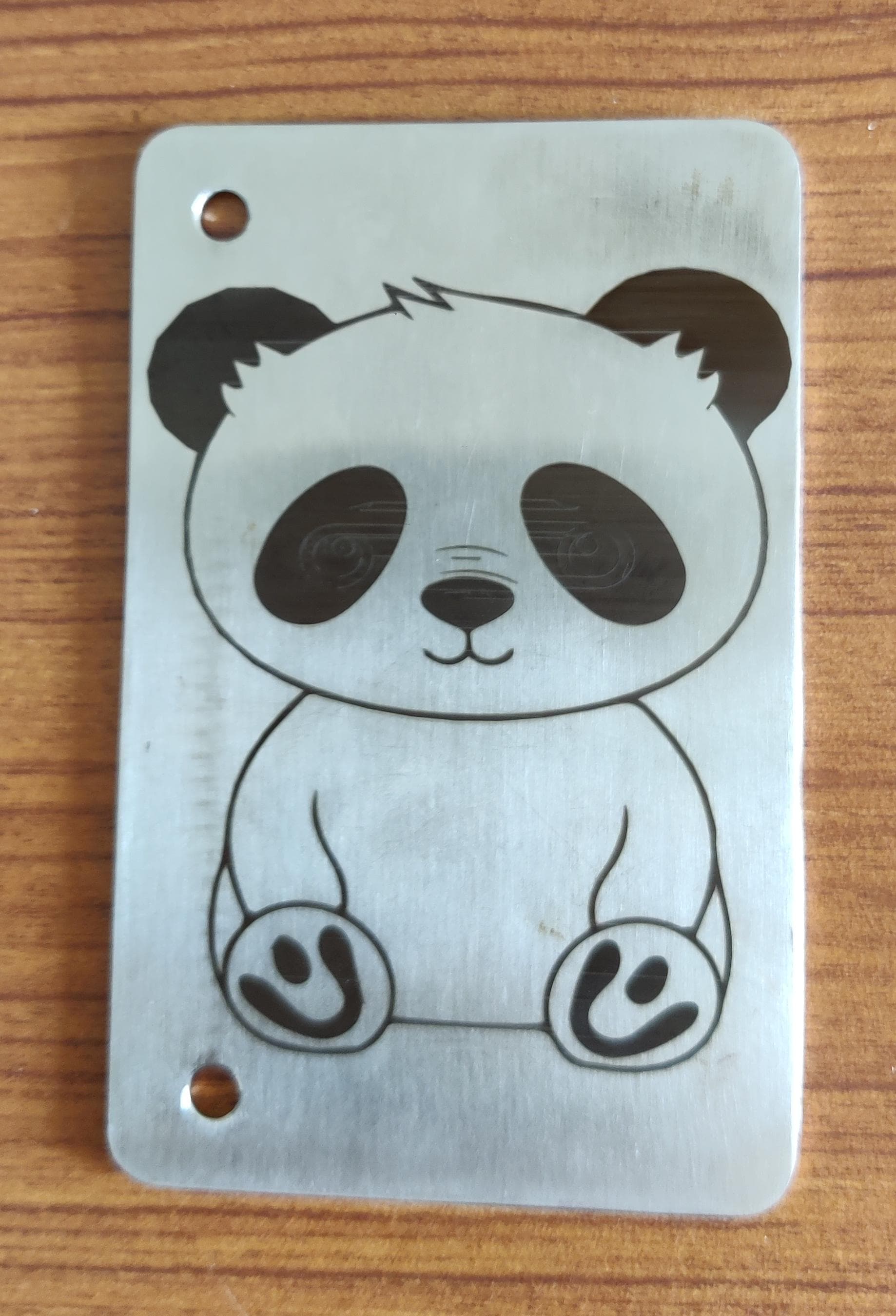
Heroshot
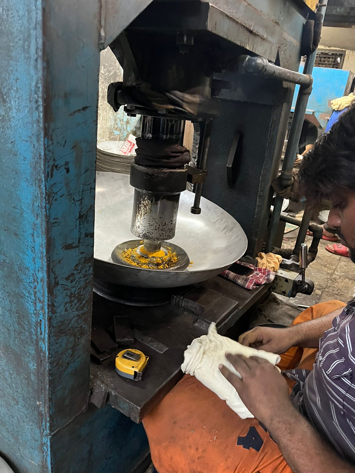
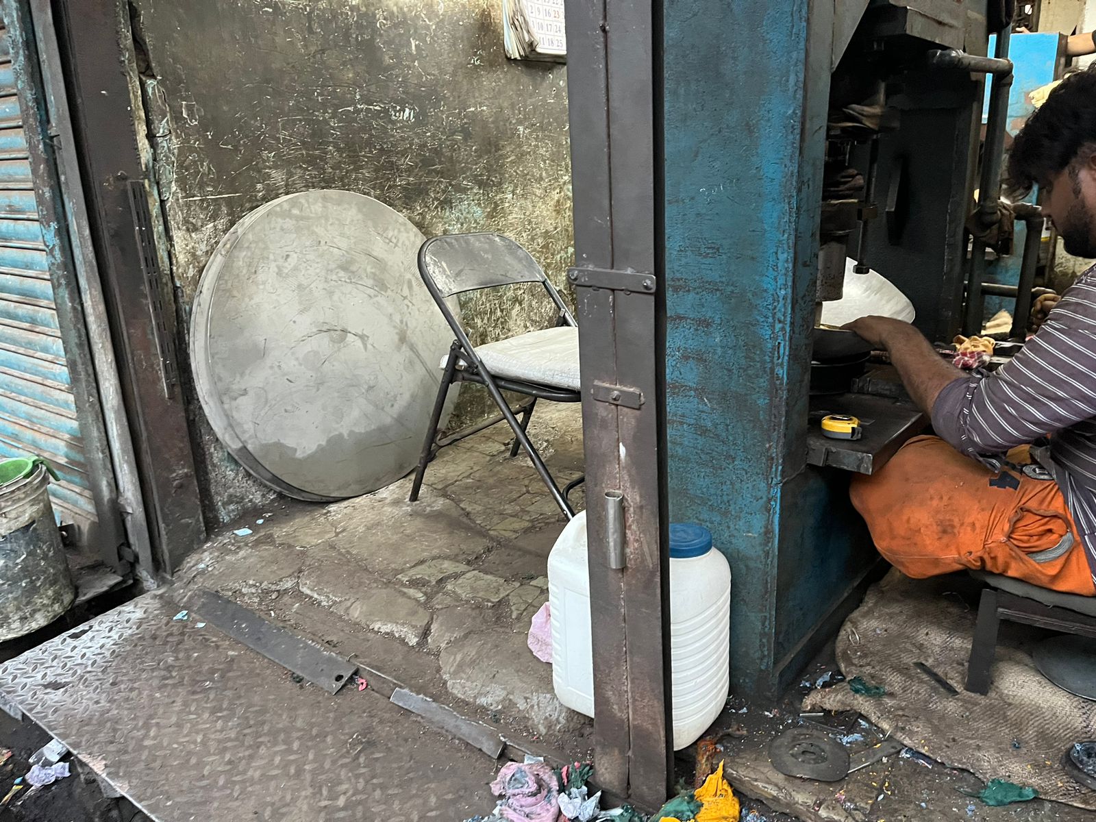
Big cooking container making
Next thing I will like to try is this how to make containers.
As we raeched the metal laser cutting workshop early, we were roaming here and there, and we found one very interesting thing there, they were making very big containers from a flat metal sheet, below are the images and videos of the same.
2 people were sitting opposite to each other and they were rptating and pushing the thing to get the desired shape.
It was quite interesting !!.
Waterjet Cutting
We also saw waterjet cutting there but as my designs had patterns I made it on metal laser cutting.
Learnings
It was quite a good experience going at the workshop as I saw and learned many things which was nearby the workshop.
1. Metal laser cutting and waterjet cutting are both very noisy processes.
2. Metal laser cutting can achieve finer detail, making it better for intricate patterns compared to waterjet cutting.
3. Waterjet cutting, on the other hand, can handle thicker metals and other materials like glass, offering a wider range of material thicknesses.
4. Additionally, waterjet cutting produces much cleaner edges, while metal laser-cut pieces often require sanding and deburring.
5. Oxygen and nitrogen gas ut was also something new which I learned.
Design Files
Metal Clock files
Metal etching ai file
Metal etching dxf file
Image Credits
All images of this page are credited below.