Networking and Communications
The focus of this week's task involved grasping the concepts of networking and communication among multiple electronic devices. Initially, we explored the distinct methods and terminology associated with wireless and wired networking.
Types of Networks
1. Wired Network:
Wired networks use physical cables, such as Ethernet cables, to connect devices together. Data is transmitted through these cables using electrical signals. Wired networks are known for their reliability and security, as they are less susceptible to interference and unauthorized access compared to wireless networks. However, they may require more infrastructure and installation effort.
2. Wireless Network:
Wireless networks utilize radio waves to transmit data between devices without the need for physical cables. Devices connect to the network through wireless access points or routers. Wireless networks offer flexibility and convenience, allowing users to connect to the internet and share resources from anywhere within the network's coverage area. However, they may be more susceptible to interference, signal attenuation, and security risks compared to wired networks.
3. Hybrid Network:
A hybrid network combines elements of both wired and wireless networks to leverage the strengths of each. For example, a hybrid network may use wired connections for stationary devices that require high reliability and performance, while employing wireless connections for mobile devices and areas where running cables is impractical. Hybrid networks offer a balance between reliability, flexibility, and scalability, allowing organizations to optimize their network infrastructure based on their specific needs and requirements.
Types of Communications
1. Serial Communication:
This method involves sending data one bit at a time over a single wire or communication channel. It is commonly used for short-distance communication between devices, such as between a microcontroller and sensors or between two computers via a serial port.
2. Parallel Communication:
In parallel communication, multiple bits of data are sent simultaneously over multiple wires or channels. It is often used for high-speed data transfer within a computer or between closely located devices, such as between a microprocessor and memory chips.
3. Wireless Communication:
Wireless communication allows data transmission without the need for physical wires or cables. It includes various technologies such as Wi-Fi, Bluetooth, Zigbee, NFC (Near Field Communication), and RFID (Radio Frequency Identification), which enable communication between devices over short to long distances.
4. Ethernet Communication:
Ethernet is a standard communication protocol used for wired local area network (LAN) connections. It enables devices to communicate with each other over a network using Ethernet cables and switches or routers.
5. SPI (Serial Peripheral Interface):
SPI is a synchronous serial communication interface commonly used for communication between microcontrollers, sensors, and peripheral devices. It uses separate lines for data (MOSI, MISO), clock (SCK), and control (CS) signals.
6. I2C (Inter-Integrated Circuit):
I2C is a serial communication protocol that allows multiple devices to communicate with each other using only two wires (SDA and SCL). It is commonly used for interconnecting sensors, EEPROMs, LCD displays, and other peripherals in embedded systems.
7. CAN (Controller Area Network):
CAN is a serial communication protocol primarily used in automotive and industrial applications for real-time communication between microcontrollers and devices. It provides a robust and reliable communication mechanism over a bus topology.
Xiao RP2040 to Arduino UNO (I2C)
I started by looking up information about I2C online and I also refered Jesal sir's documentation to understand things more clearly.
After that we had a discussion in class in detail about what can connect with what via i2c and via wifi.
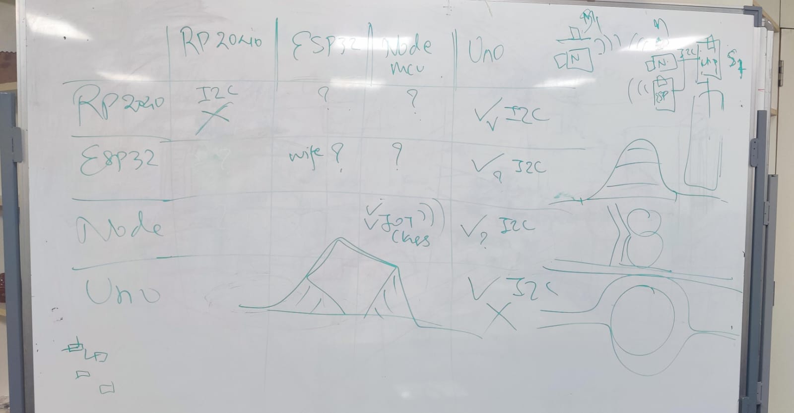
Learnings:
First, RP2040 to RP2040 communication doesn't work well because of a bug in the chip. Second, you need to be careful about voltage differences when connecting RP2040 to other devices. More details are mentioned in Jesal sir's documentation
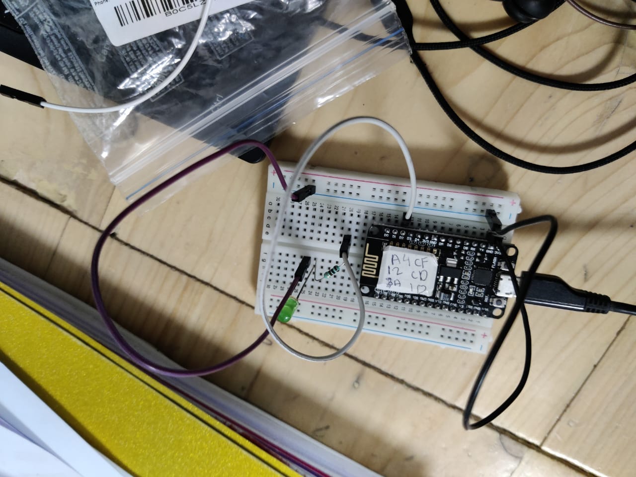
So, I decided to use the XIAO RP2040 as the Master and the Arduino UNO as the Slave.
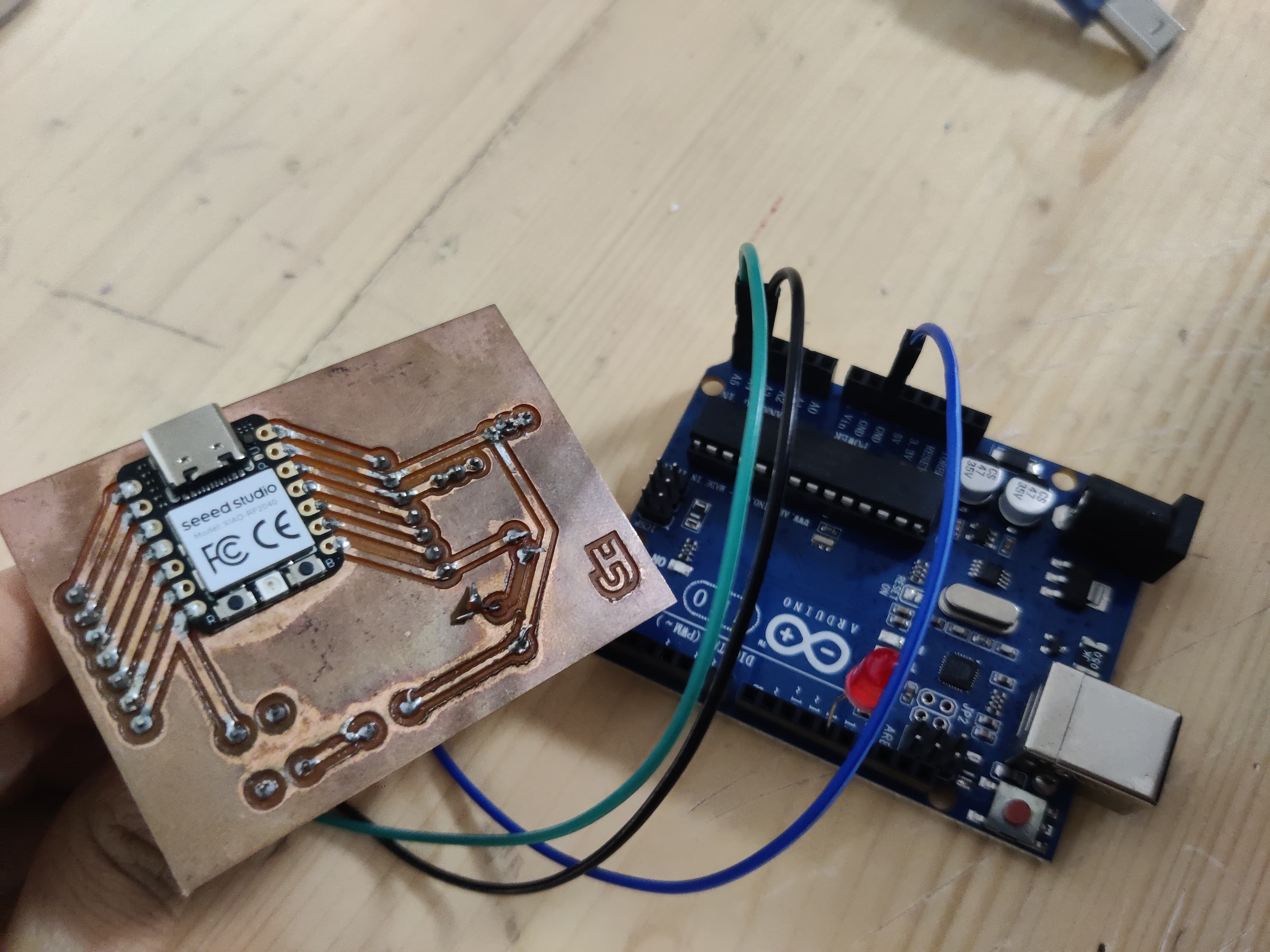
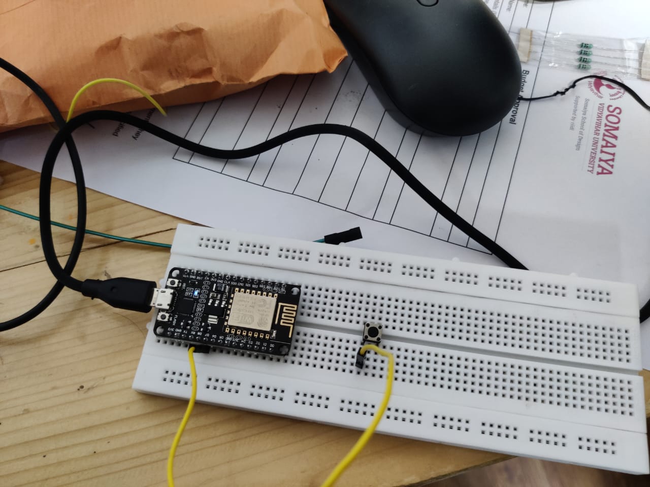
Wiring the Components
Arduino UNO to Standard LED
Anode (Long Leg): Connect to digital pin 12 on the Arduino UNO.
Cathode (Short Leg): Connect to the GND pin on the Arduino UNO.
I2C Communication
SDA: Connect the SDA pin of the RP2040 (D4) to the SDA pin of the Arduino UNO (A4).
SCL: Connect the SCL pin of the RP2040 (D5) to the SCL pin of the Arduino UNO (A5).
GND: Connect the GND pins of both microcontrollers together.
"Be careful because the XIAO works at 3.3V and the Uno works at 5V. The I2C connection uses the voltage of the Master device. So, the XIAO can be the Master with the Uno, but not the other way around."
Code
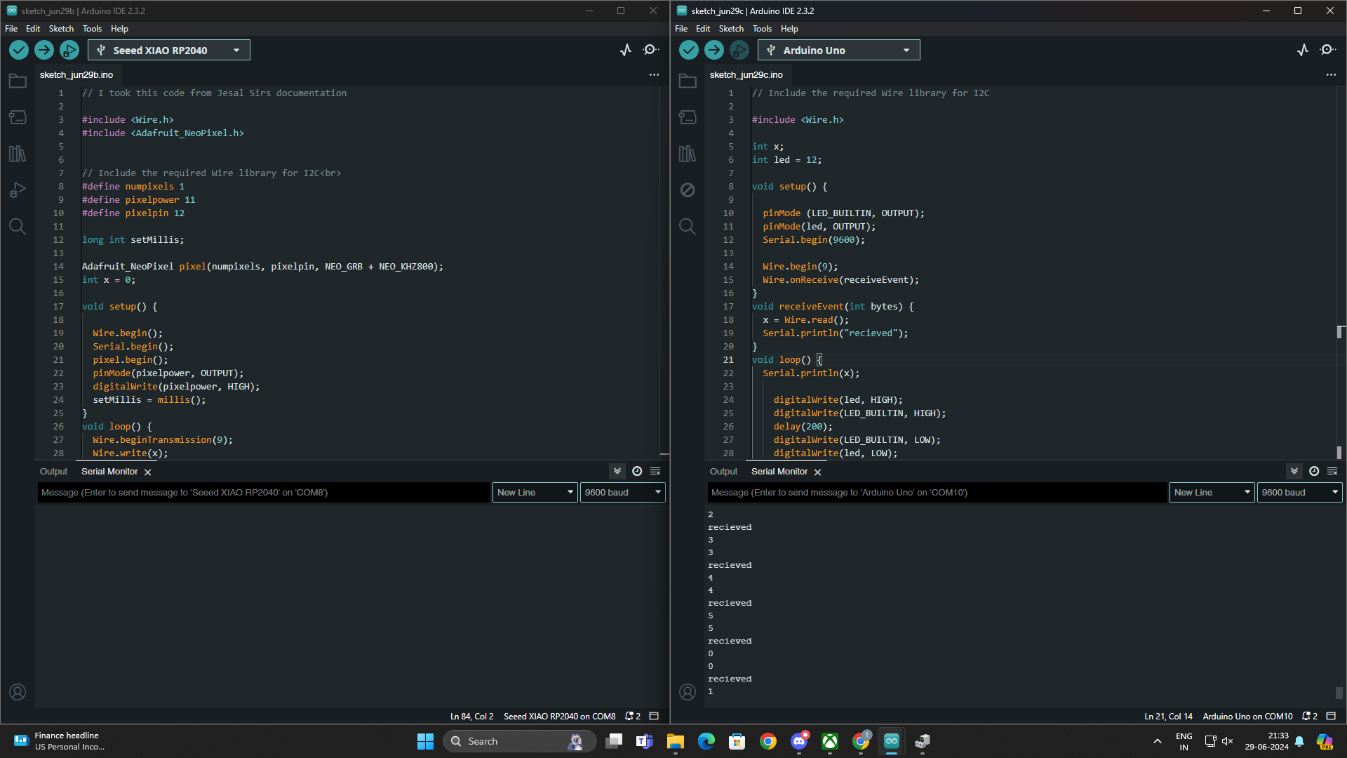
Rp2040 Code (primary code)
    // I took this code from Jesal Sirs documentation

#include
#include


// Include the required Wire library for I2C

#define numpixels 1
#define pixelpower 11
#define pixelpin 12

long int setMillis;

Adafruit_NeoPixel pixel(numpixels, pixelpin, NEO_GRB + NEO_KHZ800);
int x = 0;

void setup() {

  Wire.begin();
  Serial.begin();
  pixel.begin();
  pinMode(pixelpower, OUTPUT);
  digitalWrite(pixelpower, HIGH);
  setMillis = millis();
}
void loop() {
  Wire.beginTransmission(9);
  Wire.write(x);
  Wire.endTransmission();

//  long int setMillis = millis();
  if (x == 0)
  {
    pixel.setPixelColor(0, pixel.Color(255, 0, 0));
    pixel.show();
       delay(200);
  }
  if (x == 1)
  {
    pixel.setPixelColor(0, pixel.Color(0, 255, 0));
    pixel.show();
       delay(200);
  }
  if (x == 2)
  {
    pixel.setPixelColor(0, pixel.Color(0, 0, 255));
    pixel.show();
       delay(200);
  }
  if (x == 3)
  {
    pixel.setPixelColor(0, pixel.Color(255, 255, 0));
    pixel.show();
       delay(200);
  }
  if (x == 4)
  {
    pixel.setPixelColor(0, pixel.Color(0, 255, 255));
    pixel.show();
       delay(200);
  }
  if (x == 5)
  {
    pixel.setPixelColor(0, pixel.Color(255, 0, 255));
    pixel.show();
       delay(200);
  }

  long int nowMillis = millis();

  // if (nowMillis - setMillis > 200)
  // {
    x++; // Increment x
    // setMillis = millis();
  // }
 if(x>5)
  {
    x = 0;
  } // `reset x once it gets 6

 delay(200);


}
Code for arduino (secondary)
    // Include the required Wire library for I2C

#include

int x;
int led = 12;

void setup() {

  pinMode (LED_BUILTIN, OUTPUT);
  pinMode(led, OUTPUT);
  Serial.begin(9600);

  Wire.begin(9);
  Wire.onReceive(receiveEvent);
}
void receiveEvent(int bytes) {
  x = Wire.read();
  Serial.println("recieved");
}
void loop() {
  Serial.println(x);

    digitalWrite(led, HIGH);
    digitalWrite(LED_BUILTIN, HIGH);
    delay(200);
    digitalWrite(LED_BUILTIN, LOW);
    digitalWrite(led, LOW);
//    delay(400);

}
Steps of setup
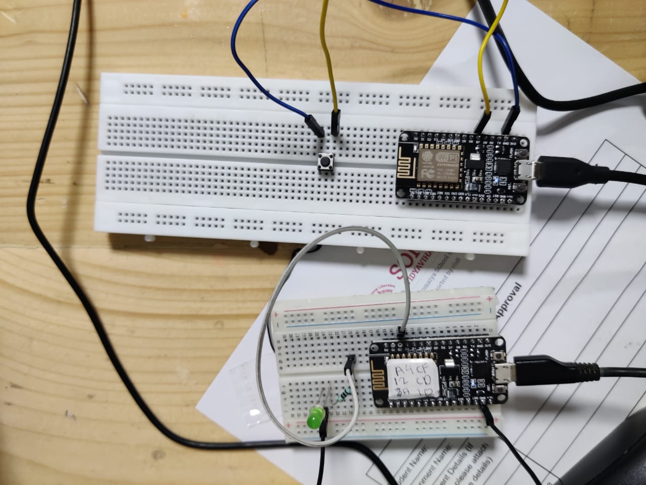
Step 01: Connections
Connect everything as mentioned and shown in the circuit above.
Step 02:Programming the Microcontrollers:
Write the Arduino code to read the state of the LED on the Arduino UNO and send this information over I2C.
Write the Arduino code to receive the LED state on the RP2040 and use it to control the onboard Neopixel.
Upload the appropriate code to the Seeed Xiao RP2040 and the Arduino UNO using the Arduino IDE.
step 03: Setting Up Communication:
The Arduino UNO, acting as the slave, transmits the LED state ('1' for on, '0' for off) via the I2C bus.
The Seeed Xiao RP2040, functioning as the master, retrieves the LED state from the Arduino UNO and uses this data to control the Neopixel accordingly.
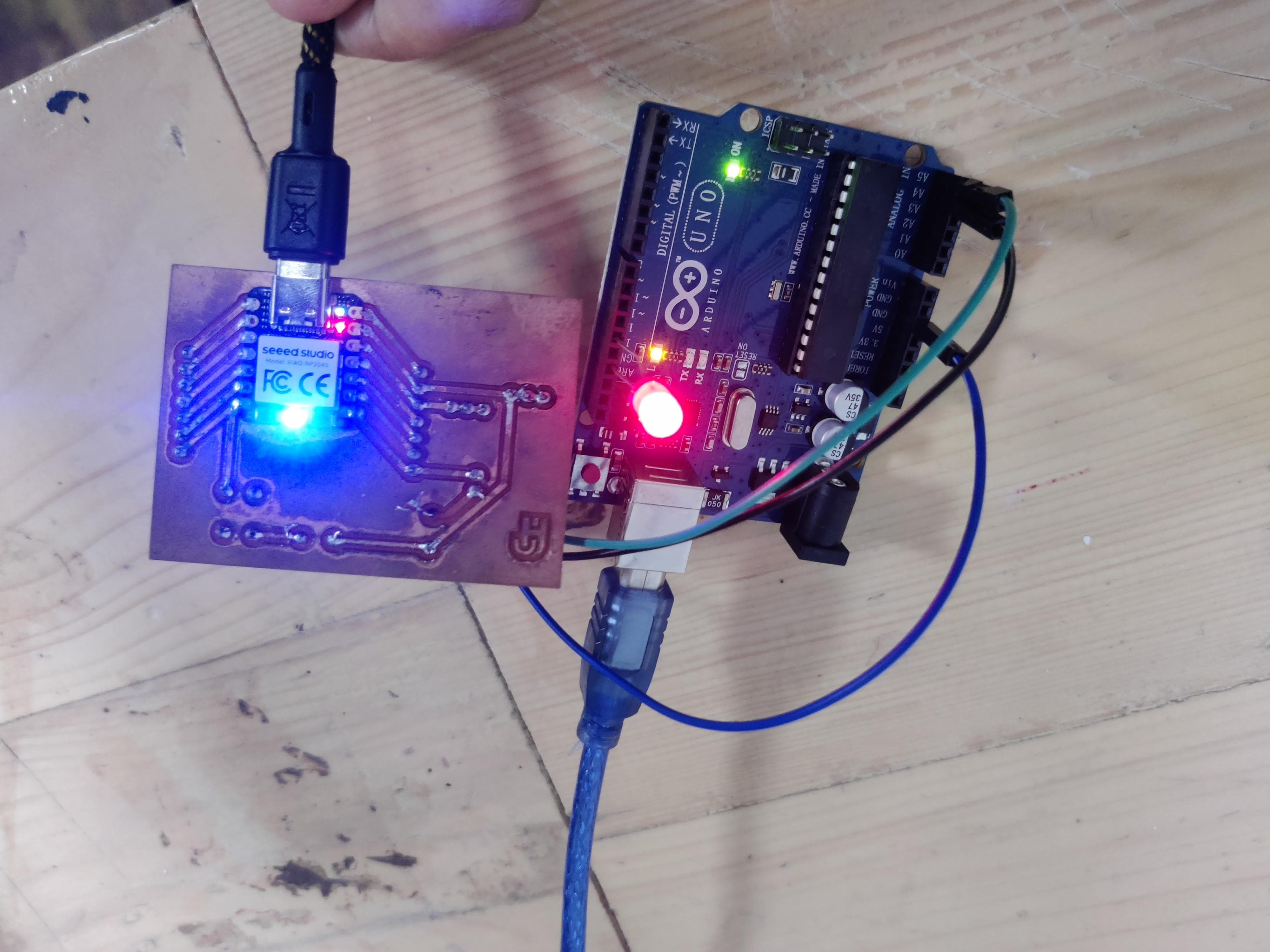
Step 04: Running the code
Power up both microcontrollers and watch the coordination between the LED on the Arduino UNO and the Neopixel on the RP2040.
The Neopixel should light up green when the LED on the Arduino UNO is on and turn off when the LED is off.
Heroshot
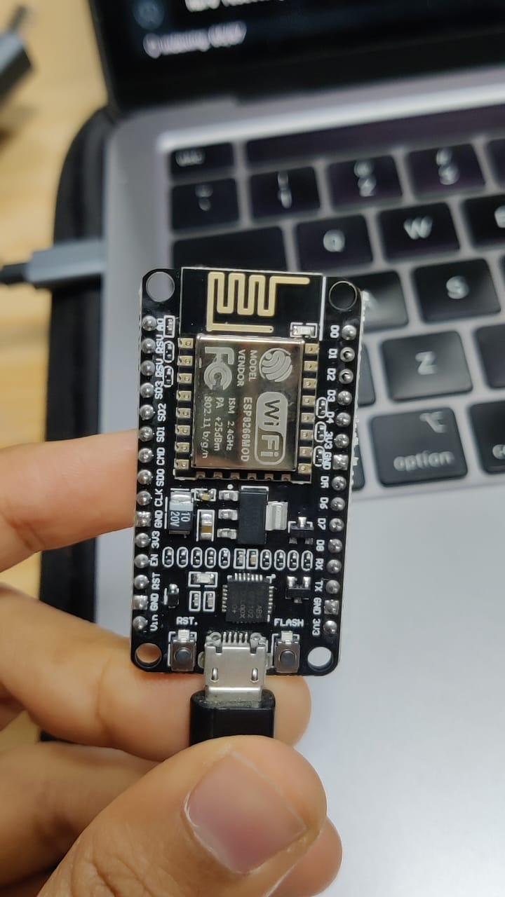
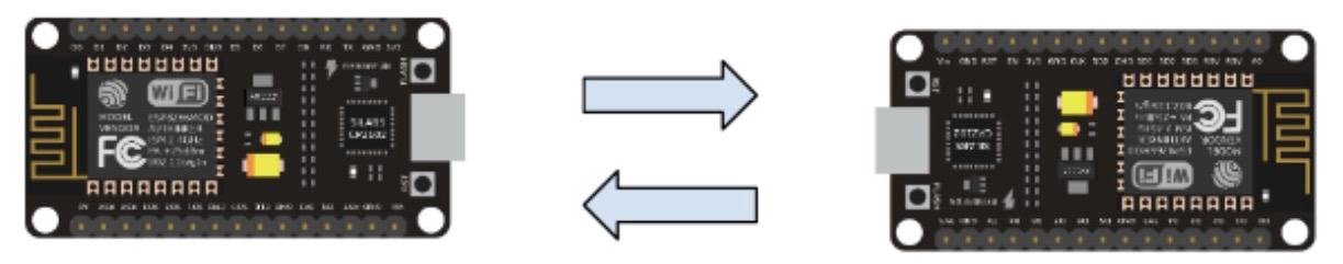
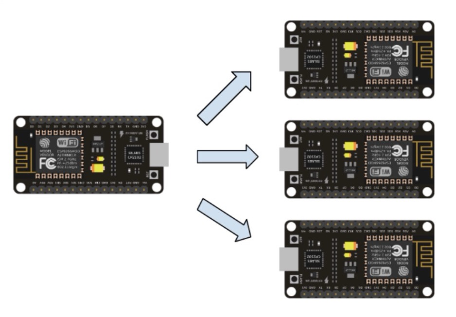
NodeMCCU (ESP8266) to NodeMCU (ESP8266)
Here I ahve tried communication between node mcu to node mcu, I did unidirectional, bidirectional and one to amny communications between them.
Steps for adding nodemcu to Arduino IDE
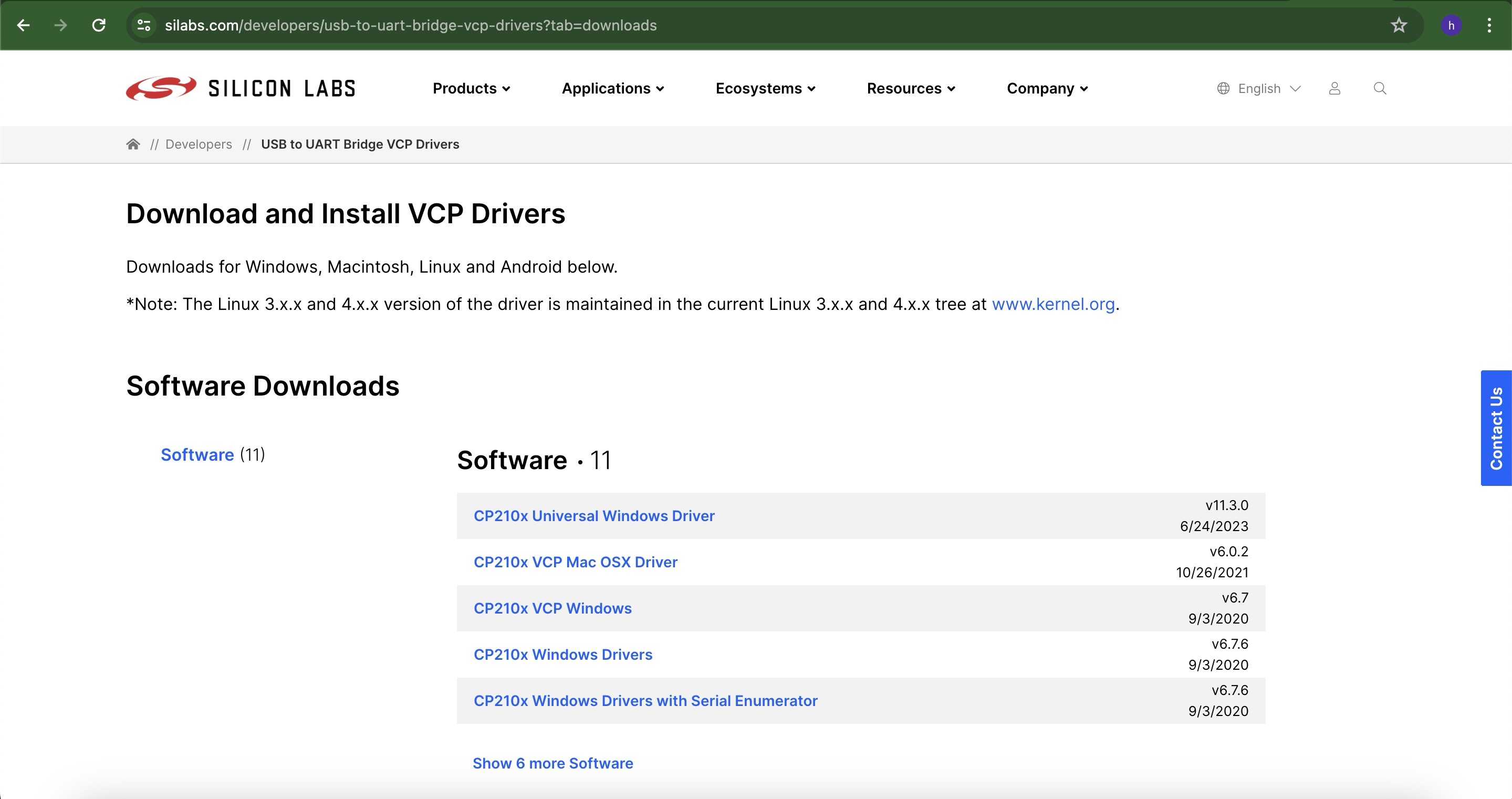
1. First you need to install some drivers for nodemcu,Here is the link to install the drivers
2. When you click on this a link a page like this will open select the appropriate one and install it on your system
After installing the driver add the NodeMCU to the IDE
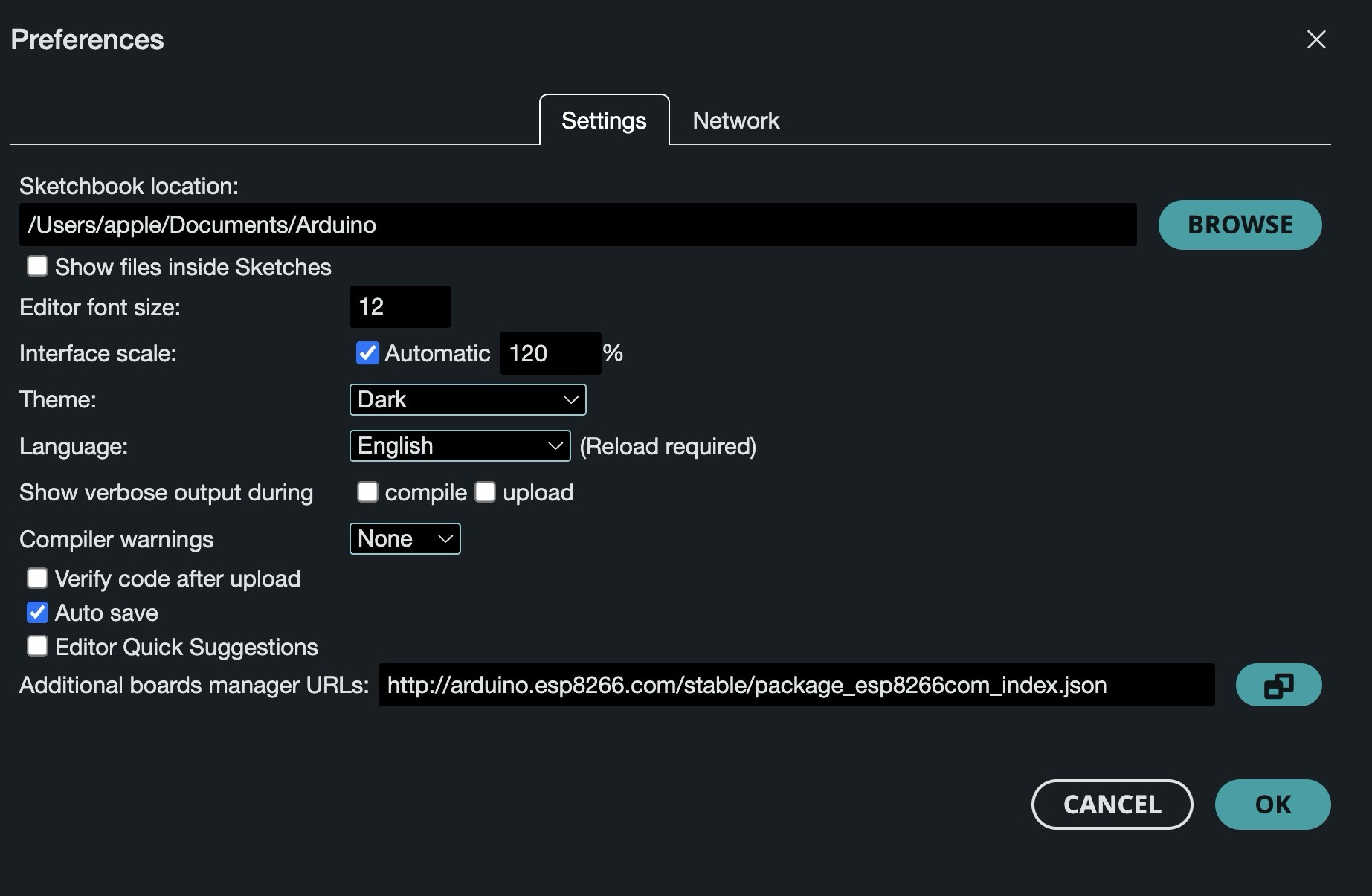
3. Go to File > Preferences
4. In the field for Additional Boards Manager URL, add the following link and click OK
Add the link which is marked in the below image.
5.. Go to Tools>Boards>Board Manager, search for ESP8266 by Community and install it
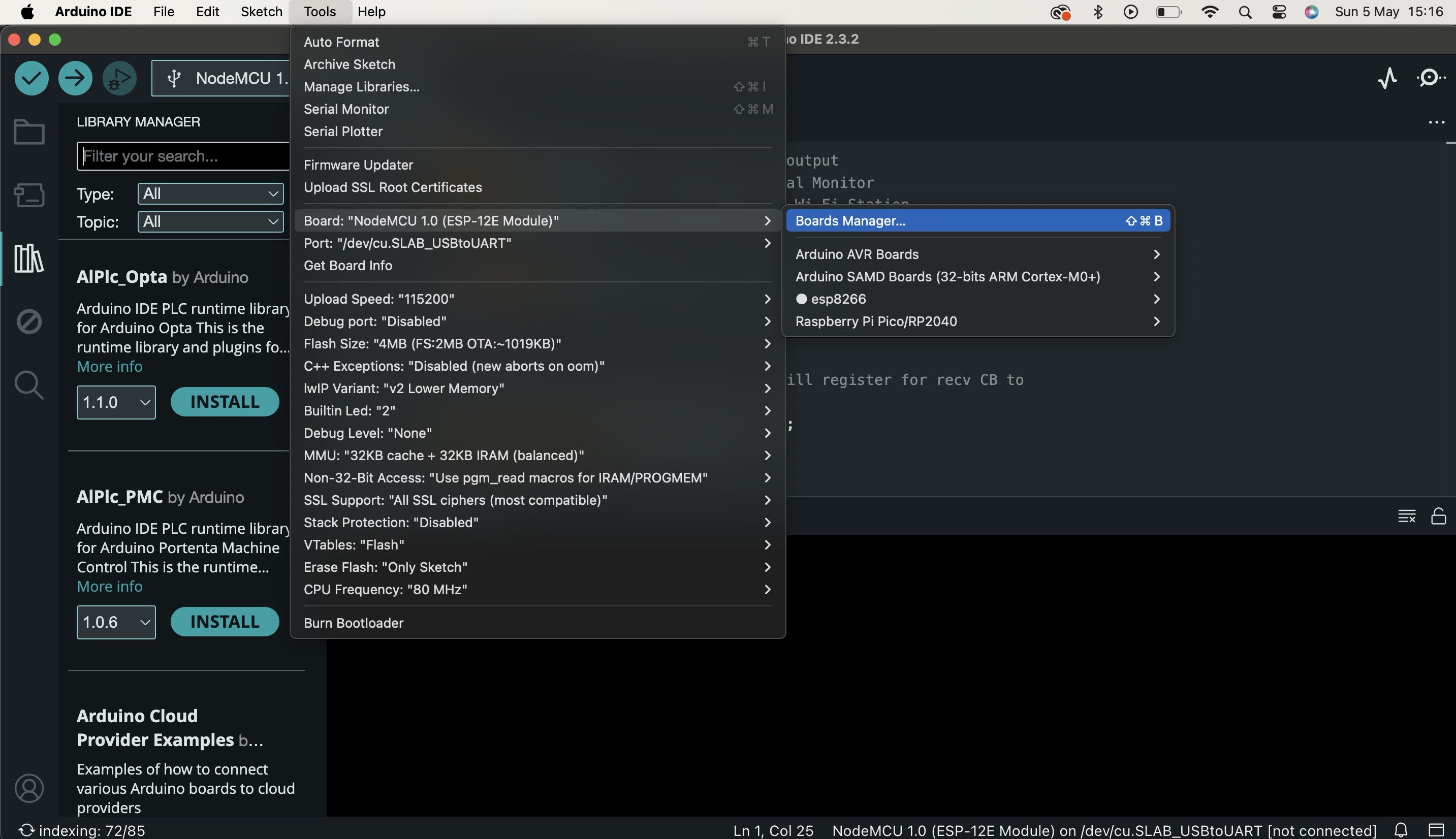
After this it will start installing wait for 1minute.
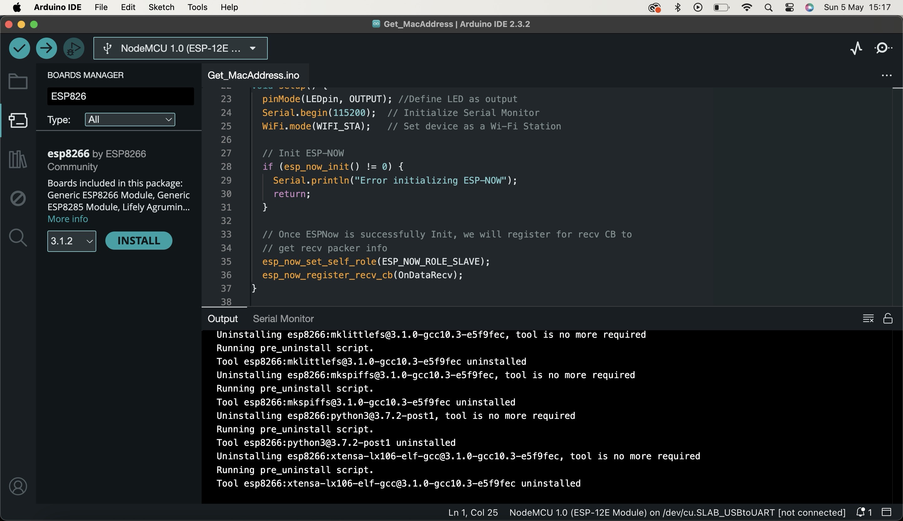
6. Go to Boards. Select esp8266 > NodeMCU 1.0 (ESP-12E Module)
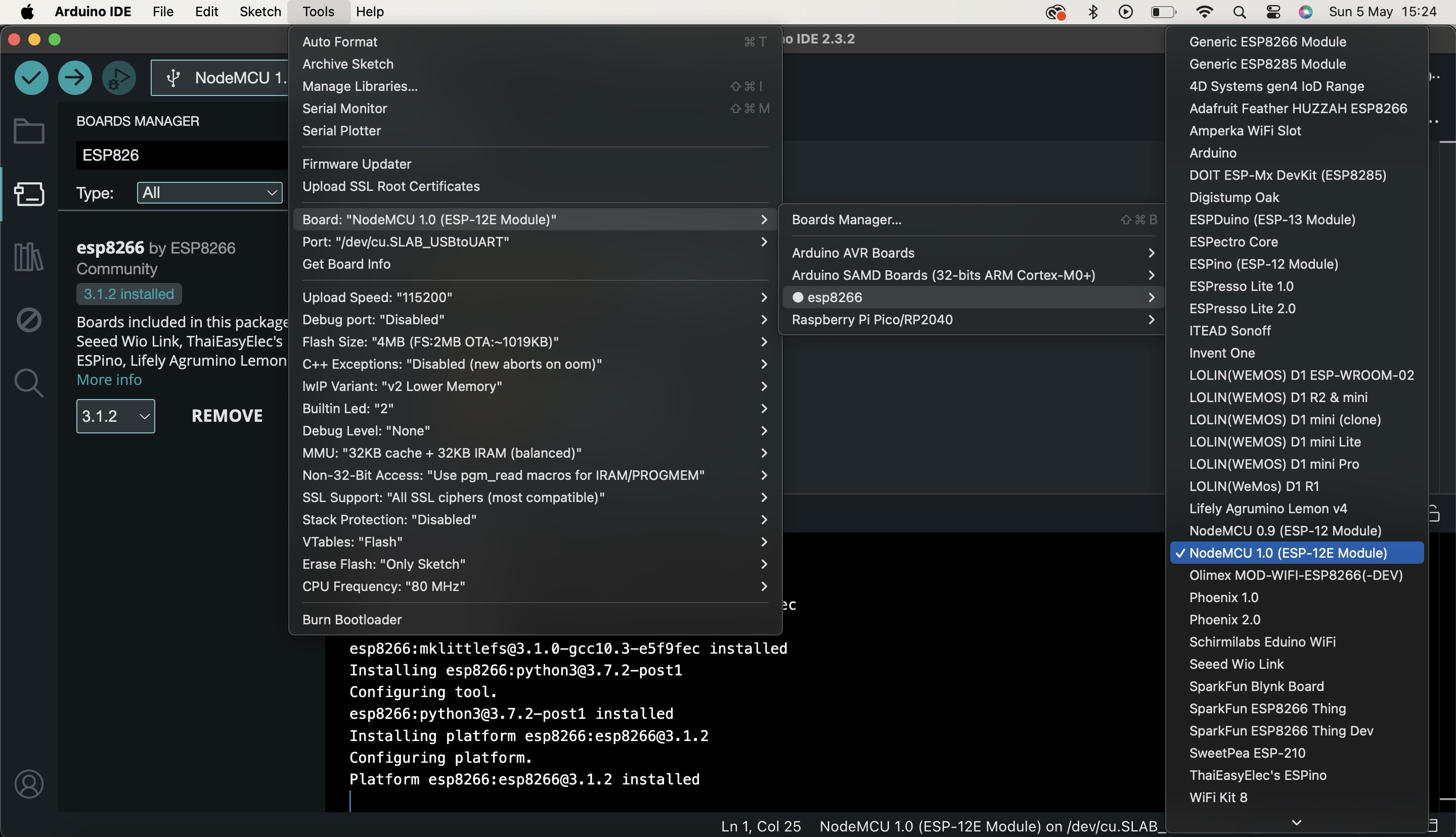
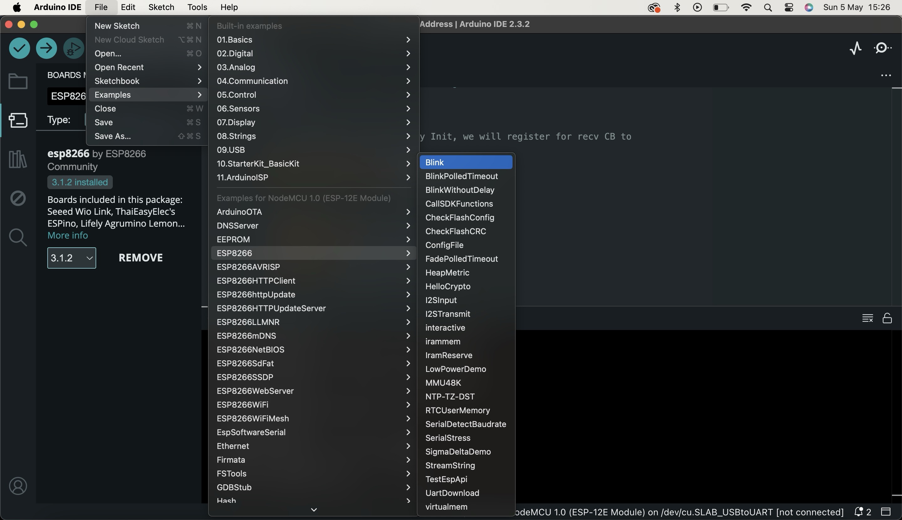
7. Select the COM Port and upload the blink sketch.
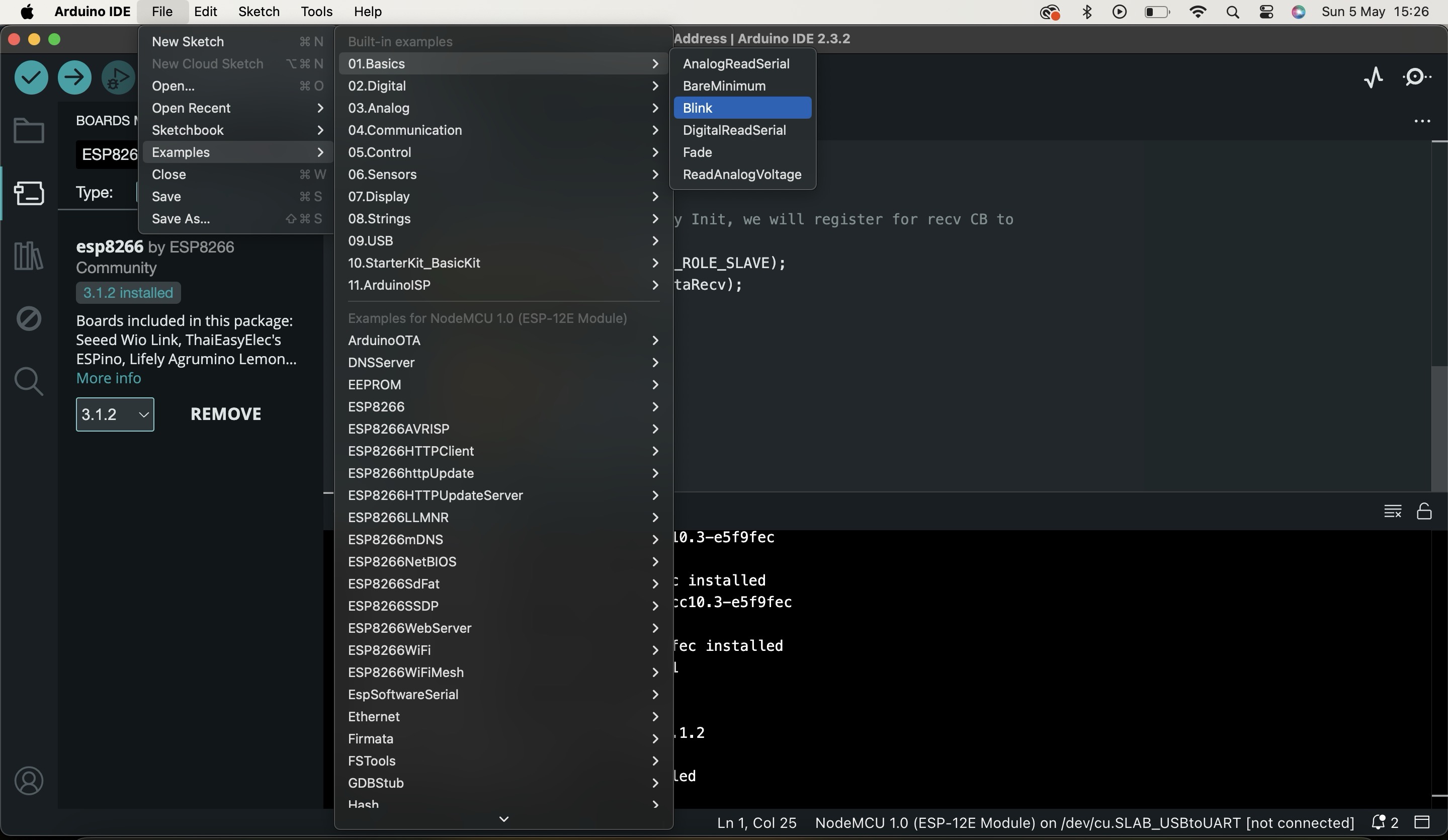
If in case this blink sketch does not work, upload ESP8266 blink sketch as shown in the figure below.
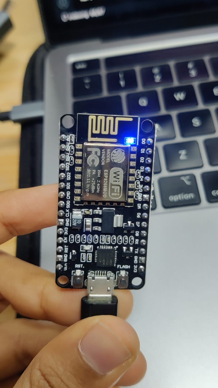
8. Now NodeMCU will start blinking
To see the video of how does it blinks click below:
MAC Address
What is a MAC address?
A Media Access Control (MAC) address is a unique identifier assigned to a network interface controller (NIC) for communications at the data link layer of a network segment. It is a hardware address that uniquely identifies each node or device on a network. MAC addresses are typically assigned by the manufacturer of the network interface card and are stored in its hardware.
MAC addresses are used for various purposes in networking, such as routing data packets across a network, ensuring that data is delivered to the correct destination, and controlling access to network resources. They play a crucial role in Ethernet networks, where they are used to identify devices and manage network traffic.
How to get MAC Address of your device?
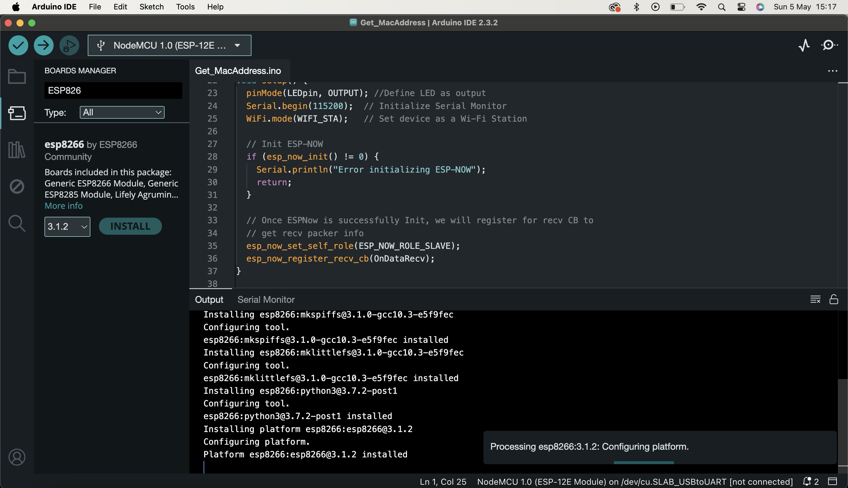
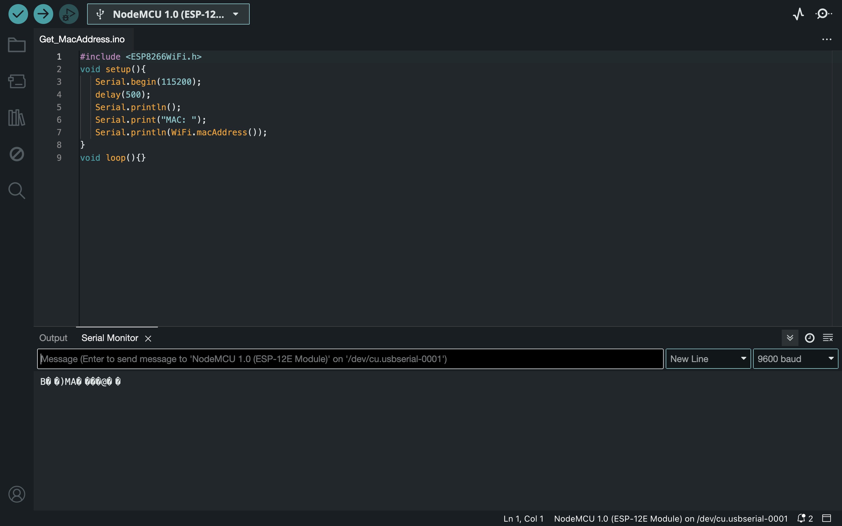
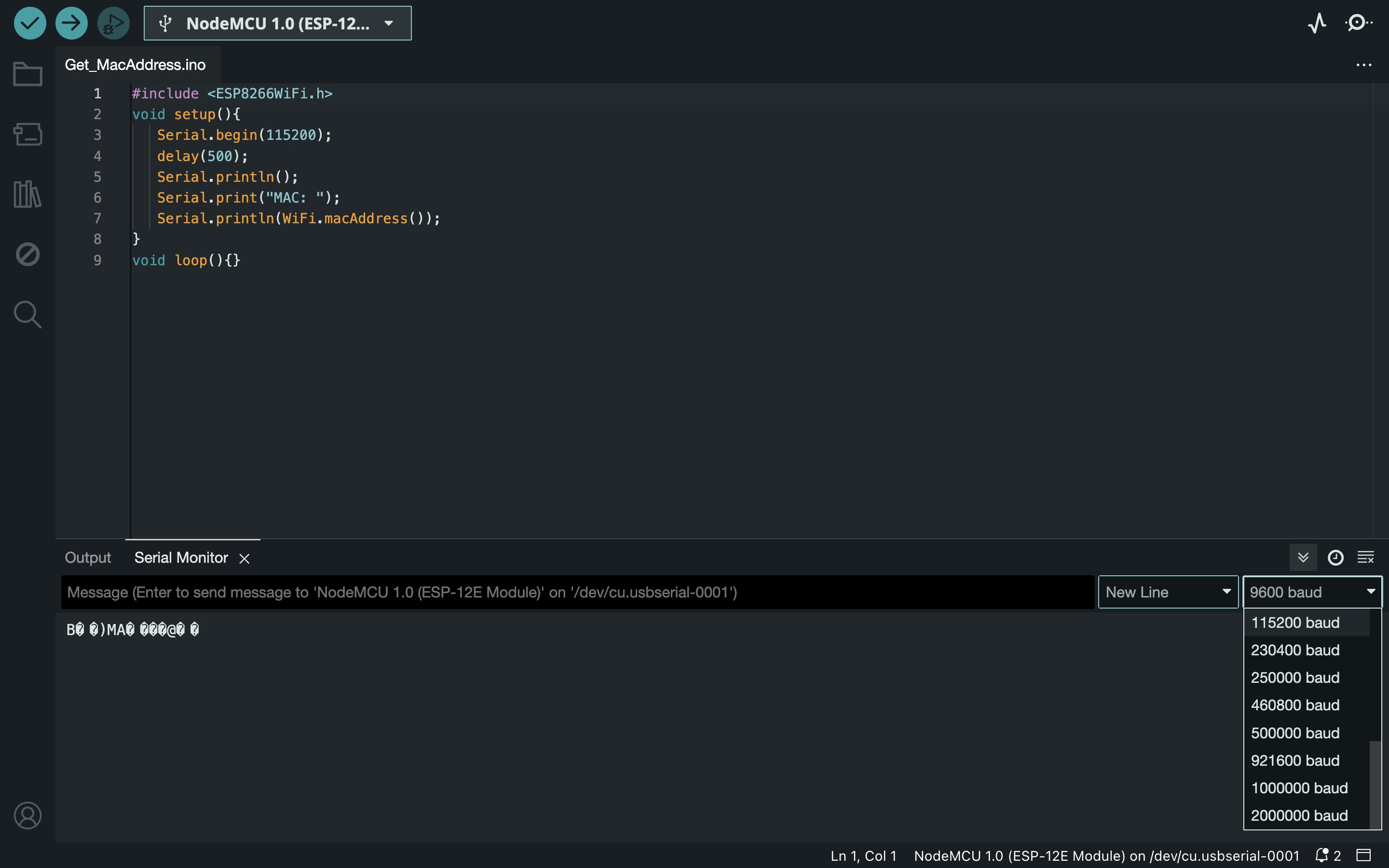
Each ESP device has a unique Mac Address required for any sort of wireless communication.
We use the following code in order to fetch it :
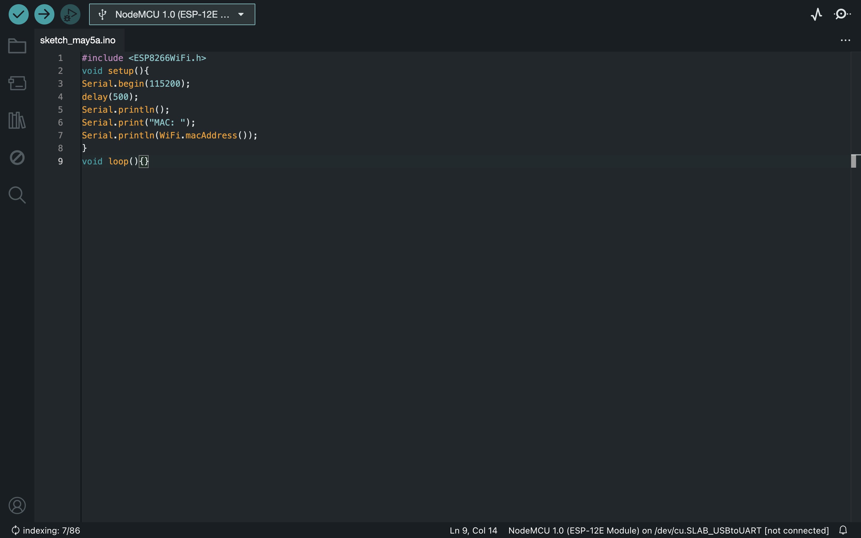
mac address file
Open the serial Monitor, set the baud rate to 115200 and press RST button on the ESP board if the MAC address is not visible.

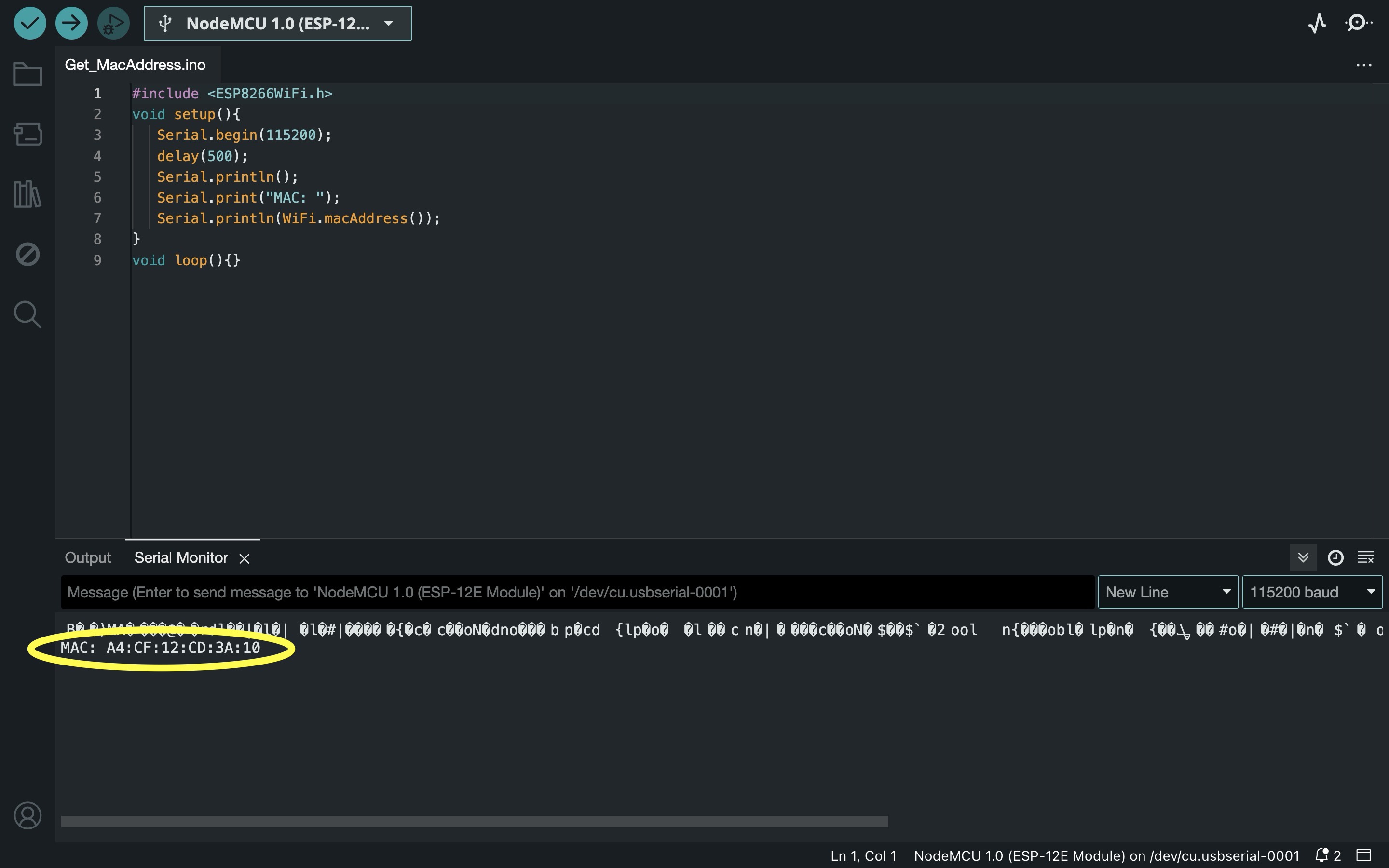
It helps to add stickers of MAC address to physical boards and color code them in order to identify Main and Secondary / device nos, etc.
ESP-NOW Useful Functions
esp_now_init()
Initializes ESP-NOW. You must initialize Wi-Fi before initializing ESP-NOW. Returns 0, if
success.
esp_now_set_self_role(role)
the role can be: ESP_NOW_ROLE_IDLE = 0,
ESP_NOW_ROLE_CONTROLLER, ESP_NOW_ROLE_SLAVE, ESP_NOW_ROLE_COMBO,
ESP_NOW_ROLE_MAX
esp_now_add_peer(uint8 mac_addr, uint8 role, uint8 channel, uint8 key, uint8 key_len)
Call this function to pair a device.
esp_now_send(uint8 mac_address, uint8 data, int len)
Send data with ESP-NOW.
esp_now_register_send_cb()
Register a callback function that is triggered upon sending data. When a message is sent, a
function is called – this function returns whether the delivery was successful or not.
esp_now_register_rcv_cb()
Register a callback function that is triggered upon receiving data. When data is received via
ESP-NOW, a function is called.
1. Unidirectional communication (Main/Secondary)
In this method, we have a main and a secondary device.
We can use the main device to send data to the secondary device to execute various
operations.
Eg . Use a push button on the Main device to trigger the LED on the Secondary device.
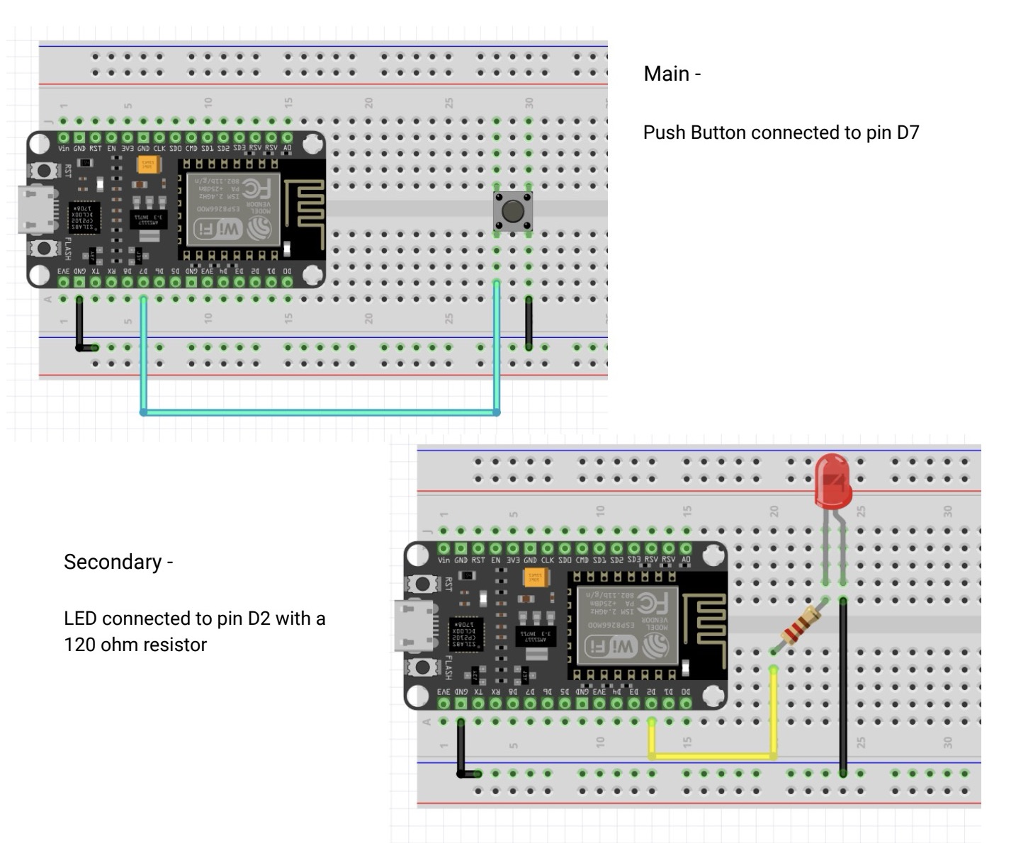
Conections
Download Code files from here
In this files change mac address and put your mac address, also add your wifi networka and password if there is wireless communication
Main_Push button code
Secondary_LED
2. Bidirectional communication
In this method, we have two devices sharing data with each other i.e. both transmitting and
receiving. Such devices are called “transceivers”.
Eg. Program 2 Controllers such that when you press the push button on Controller 1, the LED
connected to Controller 2 should glow and vice versa.
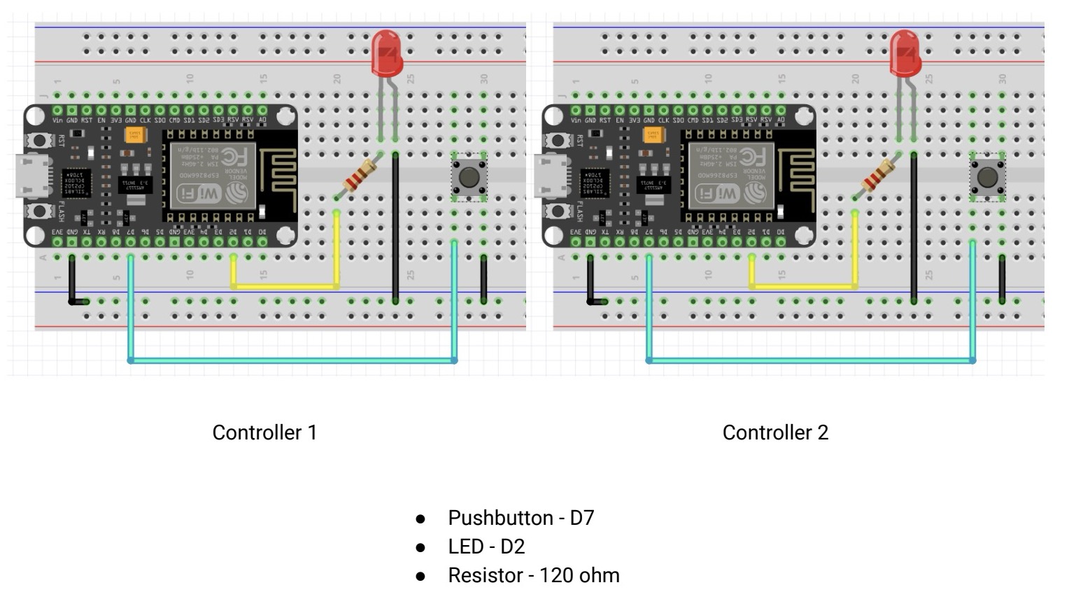
Connections
Working
Download Code files from here
In this communication there are 2 NodeMcu put the same code in 2 different laptops and put the mac address of each oher.
Bidirectional code
3. One to Many
Just like the Unidirectional communication, this uses the Main- Secondary approach, except
that there is one main and multiple secondary devices.
Simply replace the broadcast address line in Main’s sketch to-
uint8_t broadcastAddress[] = {0xFF, 0xFF, 0xFF, 0xFF, 0xFF, 0xFF};
As it was same I have not done this but just putting the concept in case someone wants to try.
Group Assignment
This week we were supposed to Send a message between two projects
We tried wireless communication using ESP Now between our two boards: Siddharth’s Xiao ESP32 S3 attached to his Quentorres and Tejas’ ESP32 CAM module attached to his Final project PCB.
Our group work is uploaded on Siddhart's Page and my personal learnings are mentioned below.
Learnings from group work
From our group assignment on networking and communication, I learned the importance of obtaining and utilizing the correct MAC addresses for wireless communication between devices, as this ensures successful connection and data transfer. Additionally, I gained practical experience in using ESPNow for wireless communication, understanding the roles of sender and receiver, and the necessity of configuring each device with the correct partner’s MAC address. I also learned about the bootloader mode requirement for uploading code to ESP devices, which is critical to avoid compilation errors and ensure smooth code execution. This hands-on project highlighted the practical steps and attention to detail necessary for successful wireless communication between microcontrollers.
Learnings from the week
This week's focus was on understanding networking and communication between multiple electronic devices. We started by exploring various networking methods, including wired, wireless, and hybrid networks, and their respective advantages and disadvantages. Additionally, we delved into different types of communication protocols such as Serial, Parallel, Wireless, Ethernet, SPI, I2C, and CAN.
In practical terms, we tackled the challenge of setting up I2C communication between the XIAO RP2040 and the Arduino UNO. We learned that RP2040 to RP2040 communication is unreliable due to a chip bug, and we must be cautious of voltage differences when interfacing different devices. By using the XIAO RP2040 as the Master and the Arduino UNO as the Slave, we successfully implemented I2C communication to synchronize an LED and a Neopixel.
Conclusion from this week
This week provided valuable insights into the complexities of electronic device communication and the importance of understanding different networking and communication protocols. We applied theoretical knowledge to practical tasks, troubleshooting issues like chip bugs and voltage mismatches. The hands-on experience of setting up and coding for I2C communication between the XIAO RP2040 and the Arduino UNO was particularly enriching. This foundational knowledge and experience will be crucial for future projects involving interconnected electronic systems.
Download Code files from here
Xiao rp2040 to arduino uno
NodeMCCU (ESP8266) to NodeMCU (ESP8266)
In this files change mac address and put your each others mac address.