Electronics Production
Week04
Group Assignment
This week´s group assignment seemed easier than the previous ones. We "only" had to identify and characterize our in-house PCB production process. This first impression was a little biased by my personal experience. I´ve mentioned before that my background is in business and management, despite that, I can be proud of having taken an Electronics workshop when I was in 7th grade, more than half my life ago haha.
I remembered the basics,such as all the parts needing to be soldered with tin on a phenolic plate. However, the process was a bit different in that era. In that time, we used a blue acid to retire all the copper. Now, the process can be done by a machine by setting different consecutive layers to cut, by hand using a cutter, or hybrid -using first the machine, then manually for details.
Next, you will see different images that describe the process held by us as a group. Fablab Queretaro´s machine is the Roland SMR20. We used the programs Vpanel for SMR20, and VCarve Pro.
First steps:
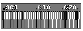
1. Import the template in Vpanel, by selecting File->Import->Import Bitmap.
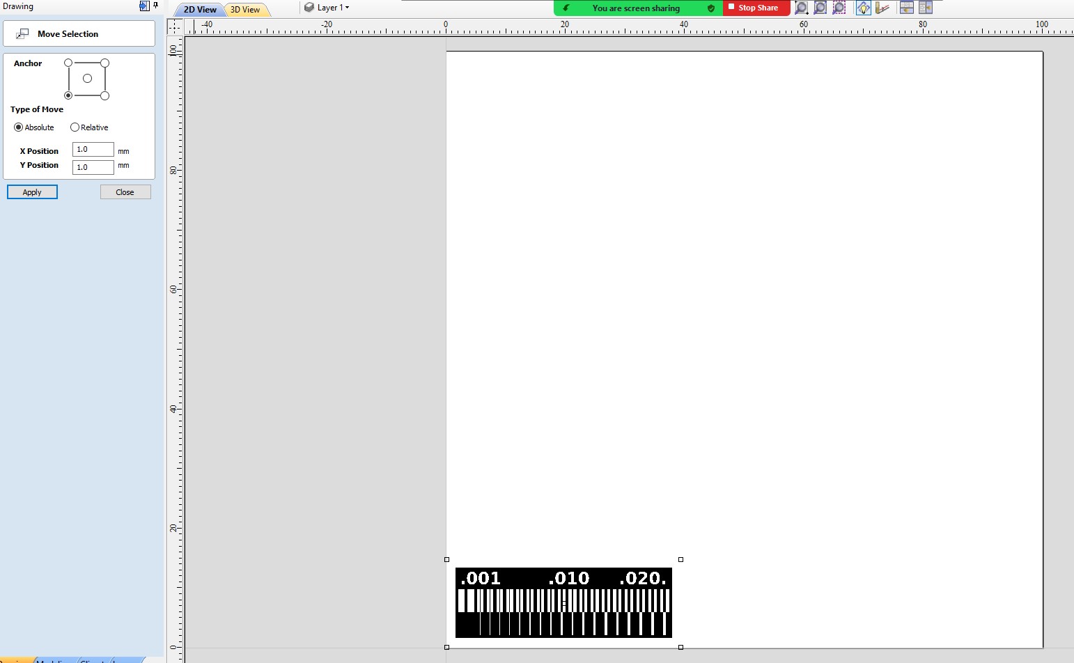
2. Move the selection to the corner. The machine always starts from the bottom left.
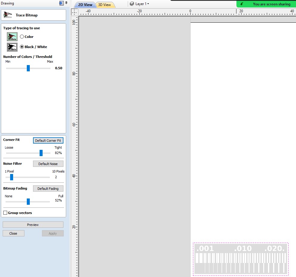
3. Remember to convert the image to lines. This time, we used the "trace bitmap" tool.
Next steps:
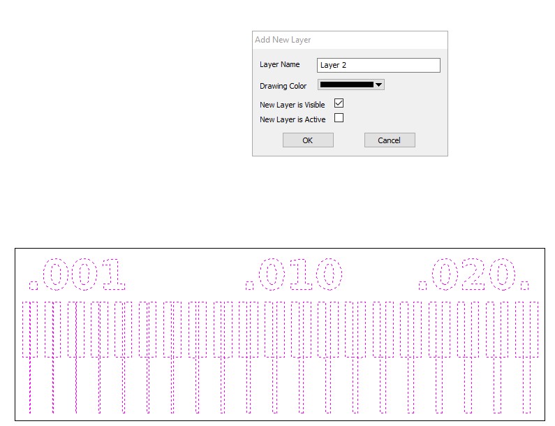
4. Be clear on what you want to do: cut or engrave. If you want to do both, set the functions to different layers.
5. To create the layers right-click the desired elements, then "Add new layer"->Name it->Ok.
6. Repeat until you get the desired number of layers.
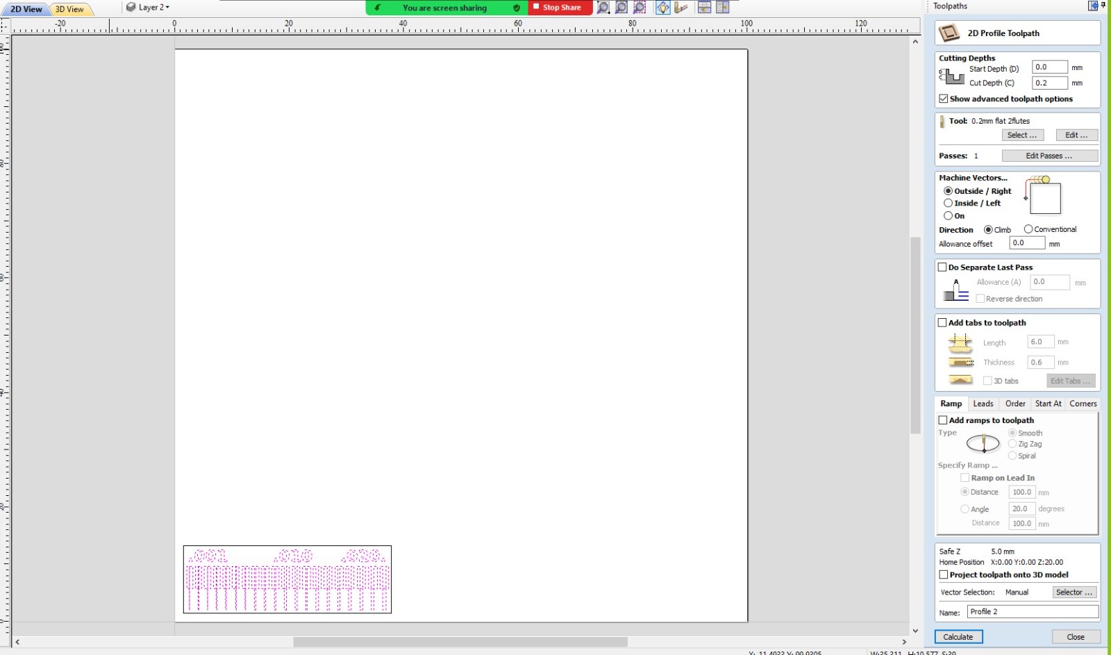
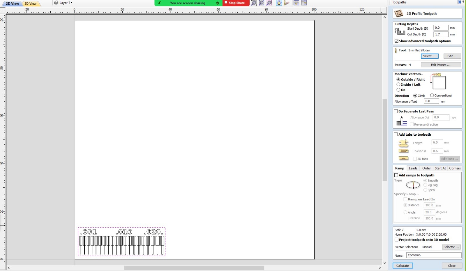
7. Investigate your machine. For our case, we set cutting depths at 1.7mm, and engraving depths at 0.2mm. We selected those due to the experience of our instuctors with the machine and commonsense: most of the drills were those sizes.
Final Steps:
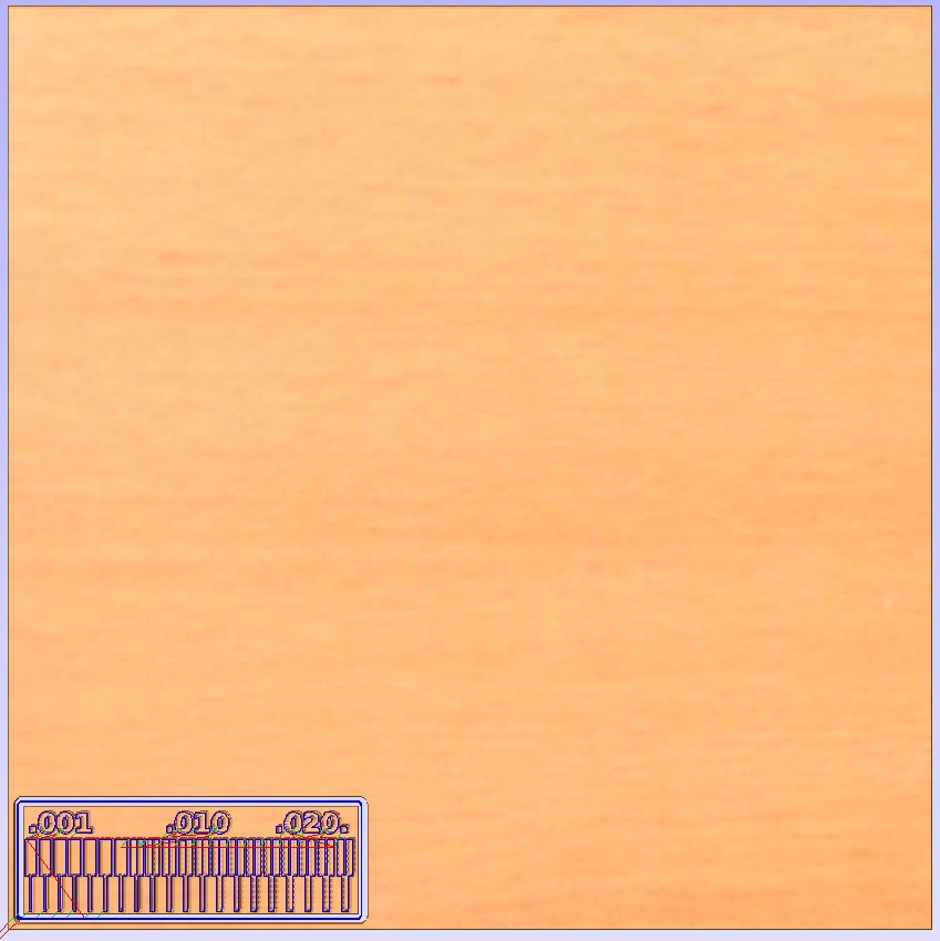
8. Preview the results, you may see them by clicking on the "3D view".
9. Merge all the layers that you want to engrave with same tool and depth. Do the same with the ones you want to cut. Group them into one function and save each collective function.
10. Go to VCarve pro.
11. Set the origin, then Cut->Add->Output.
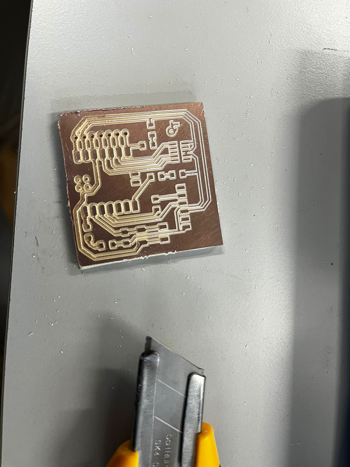
The process was really quick. The most troublesome part is to set the different layers, as it is very repetitive, thus, easier to make mistakes.The result was a bit disturbing for the perimeter. The lesson was to choose a sharper drill bit.
You may find the files we used and worked here:
Individual Assignment
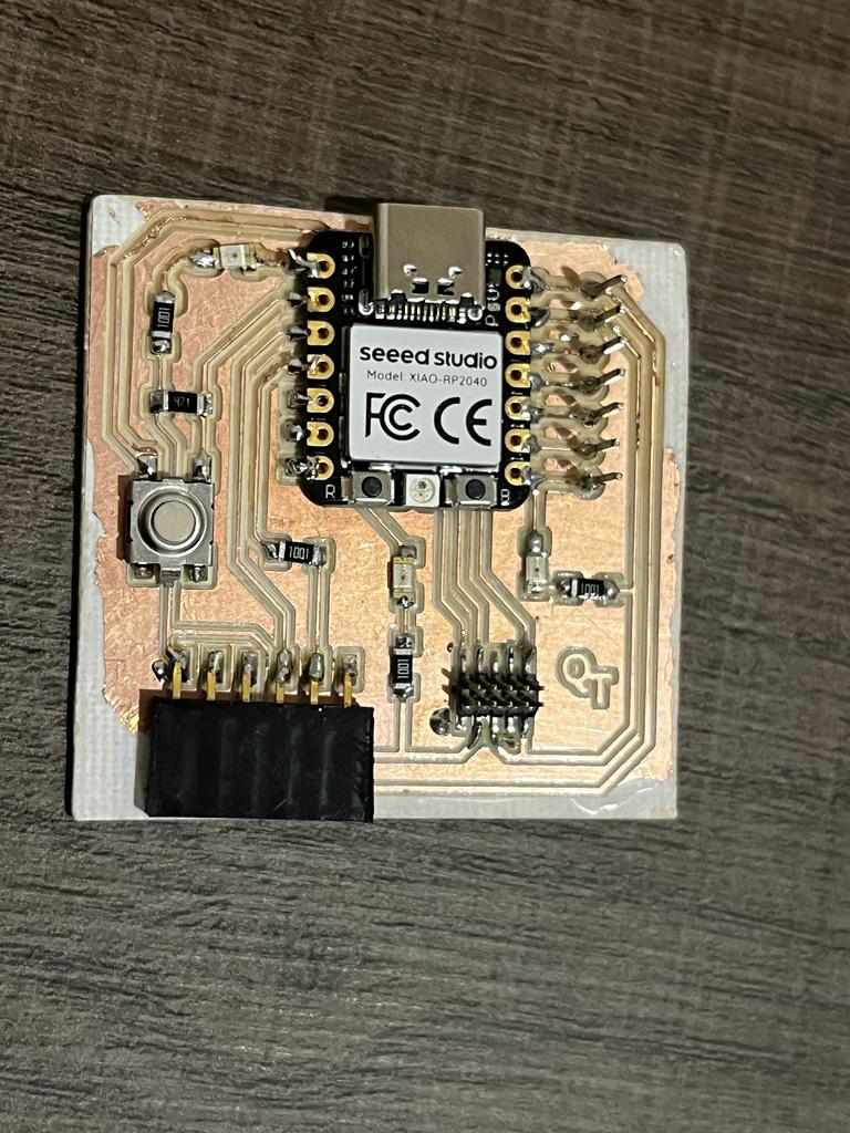
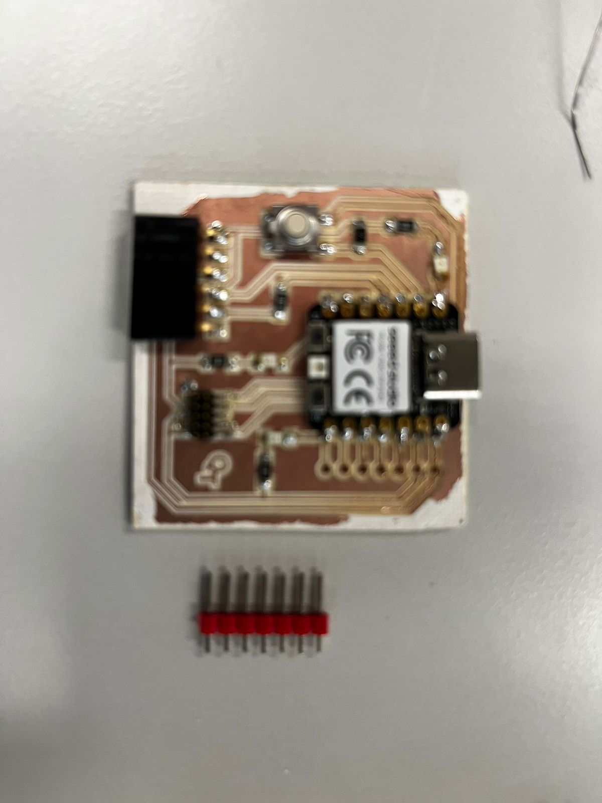
For this part of the assignment, we had to make and test a microcontroller development board, inspired by Adrián Torres´s work,which you may find here. I have to confess that his previous work was very useful, especially for me to identify the components, where they should go and to constantly compare my advancements with the desired result.Also, I took advantage of having such a great mate: Israel, who finished his work early in the week, and his learnings turned into lessons for me. As you will see, my phenolic plate was accurately cut in the first try; nonetheless, I faced some problems, too.
First, I repeated the process I explained previously for the group assignment, this time with a different file, which you may find here: template for microcontroller development board.
I will show you different parts you should focus on, to successfully achieve the desired result:
Machine
Always get familiar with which machine you are using, how it works, and which program(s) it uses
This time, the model is a Roland SMR20, and the needed programs were the same than the ones from the group assignment: VPanel for SMR20 and VCarve Pro.
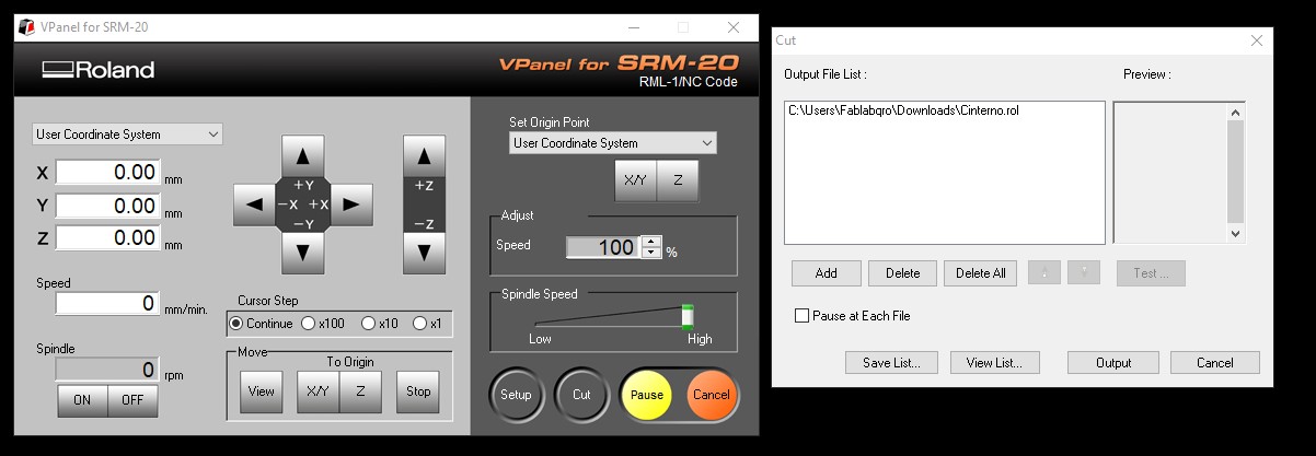
Next, I share some evidence of the Roland machine and how to set it using VCarve Pro.
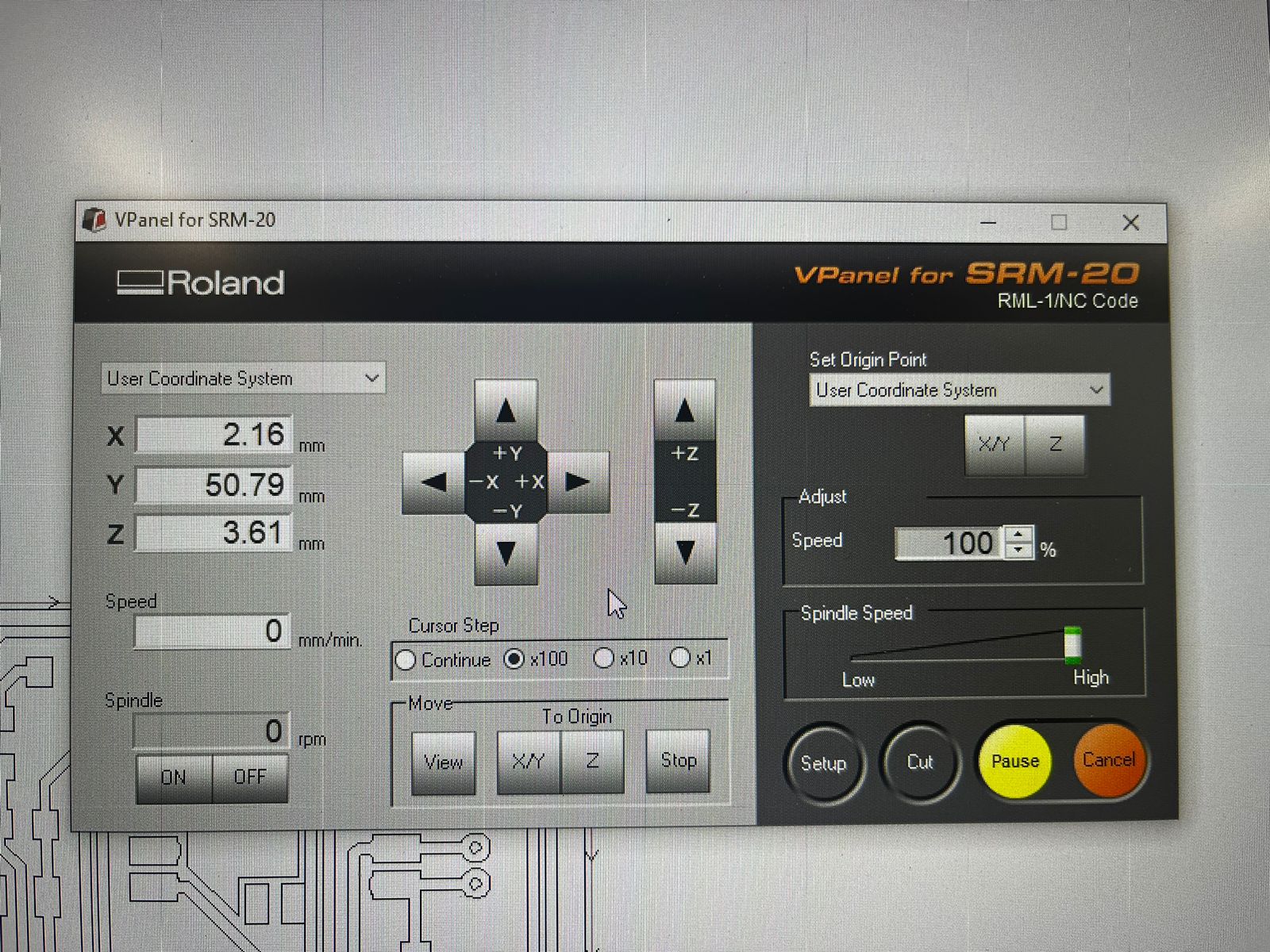
As you may see, the controls in VCarve Pro are easy to use, pretty much like a joystick, where you move vertically with the "Y" buttons, horizontally with the "X" buttons, and change heights with the "Z" buttons. The buttons on the left are to move the cutting part, the buttons on the right are to set the origin.
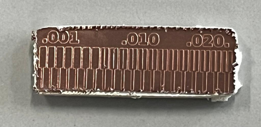
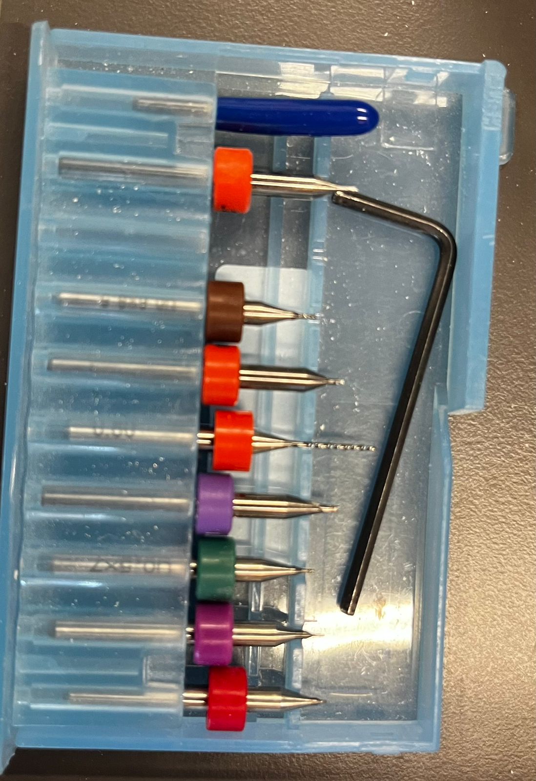
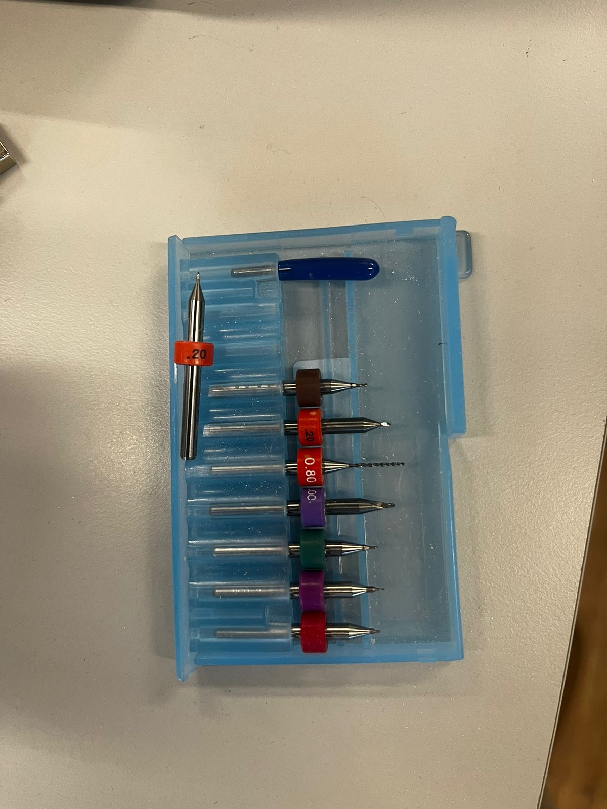
A parallel process should be done, which is reviewing and setting the drill bits. The important thing here is to visually check the endpoint, again to reduce the possibilities for mistakes. Verify that the sizes correspond with the ones set in VPanel for SMR20, that the endpoints are sharp, that they are correctly assembled into the corresponding part of the Roland, and that the origin is alligned with the phenolic plate.
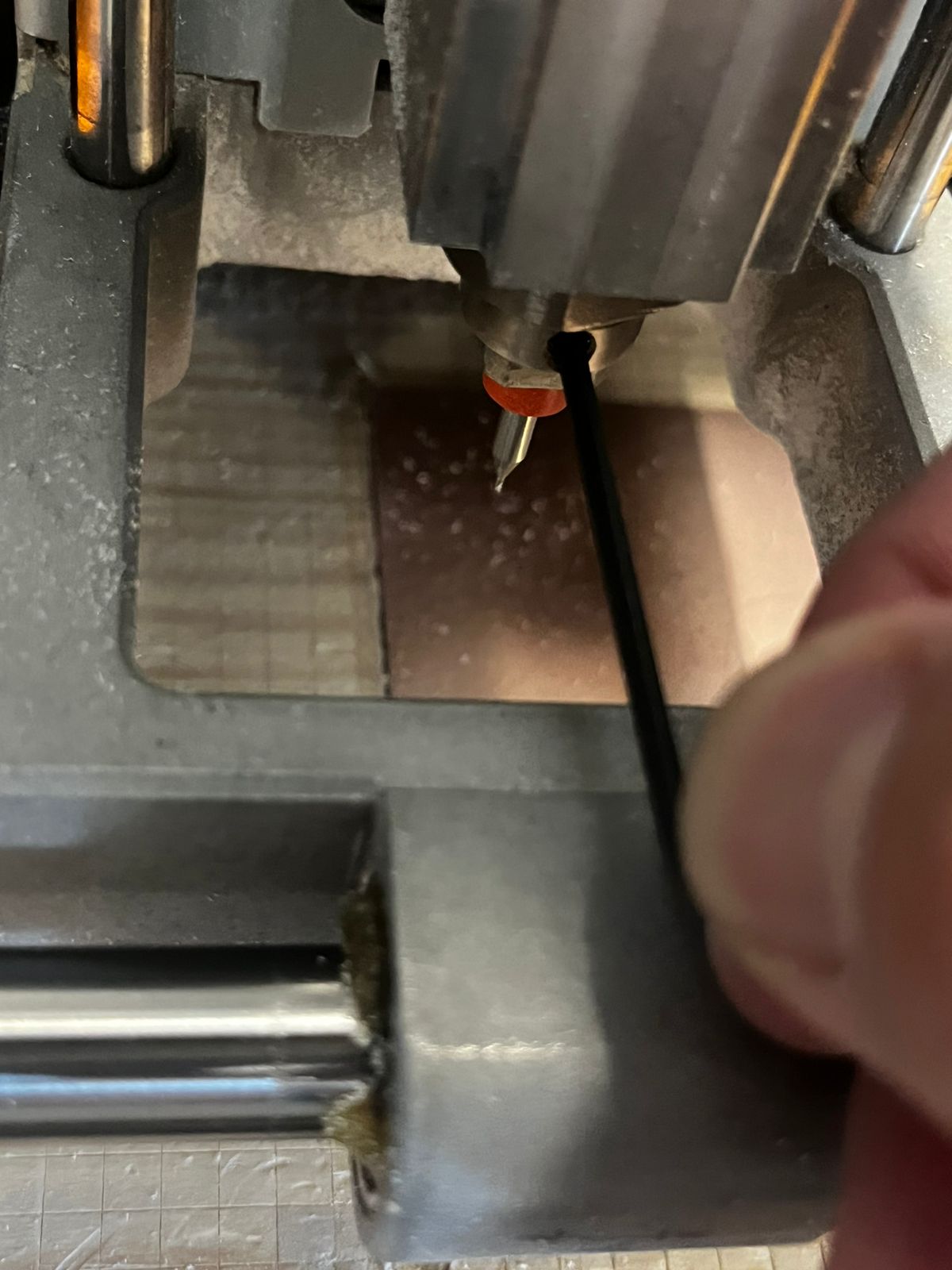
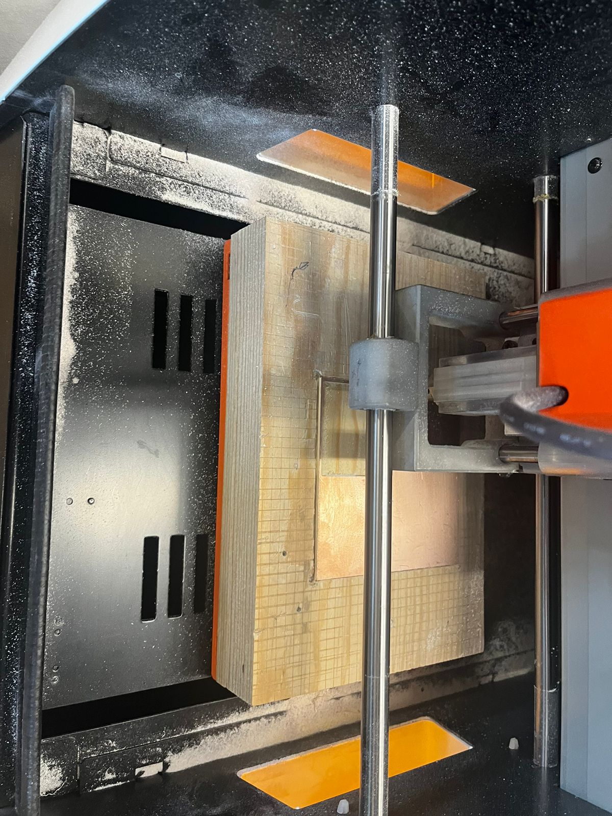
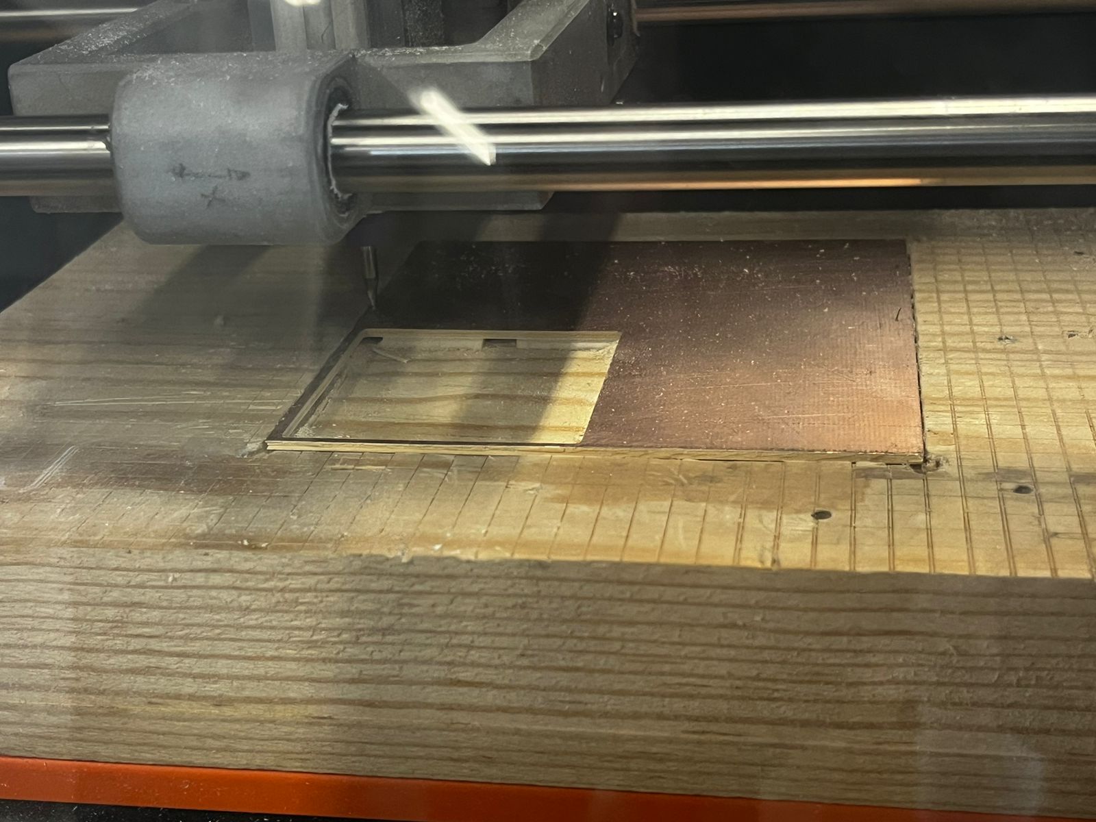
Next, you are able to see the machine performing. Notice in the third video that it first cuts the inner part, then the outter one. Perhaps logic, it is important to remember that to have more control and reduce potential mistakes.
Phenolic plates
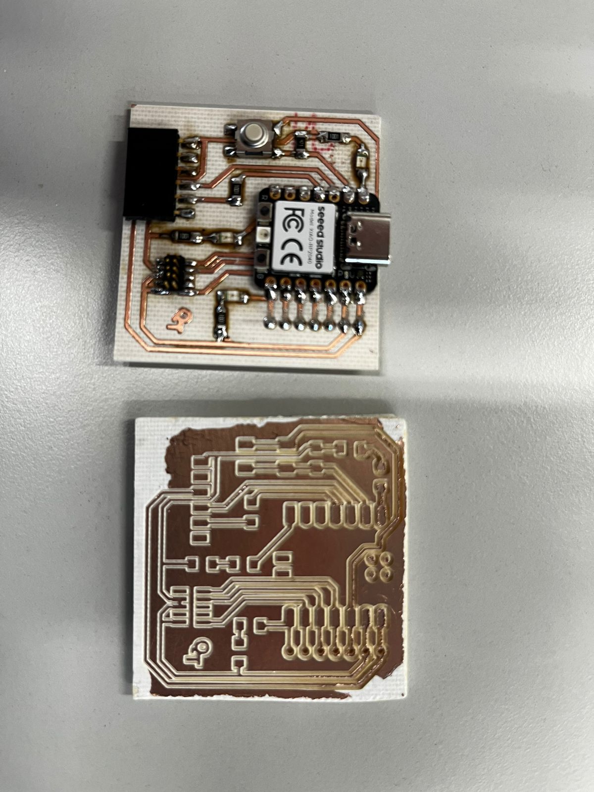
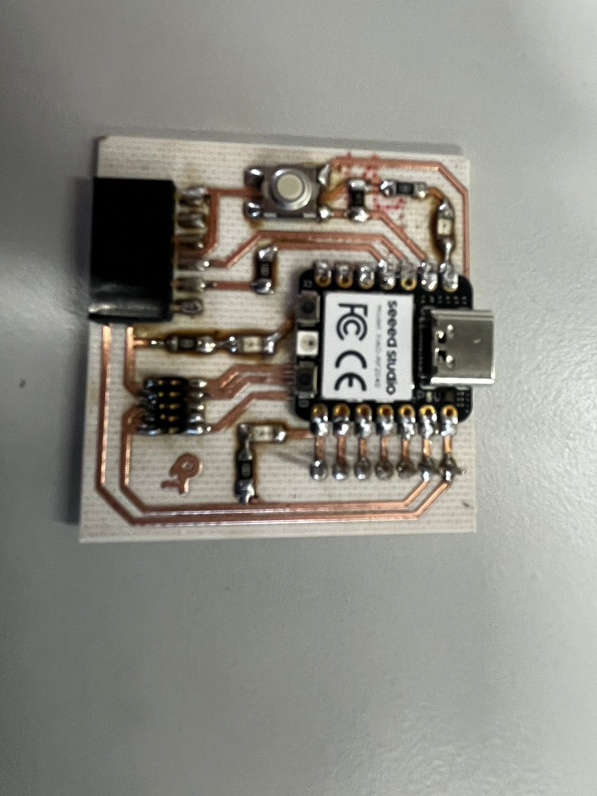
Once the Roland machine was donde with engraving and cutting, it was time to do the most challenging part: solder the components into the phenolic plate.
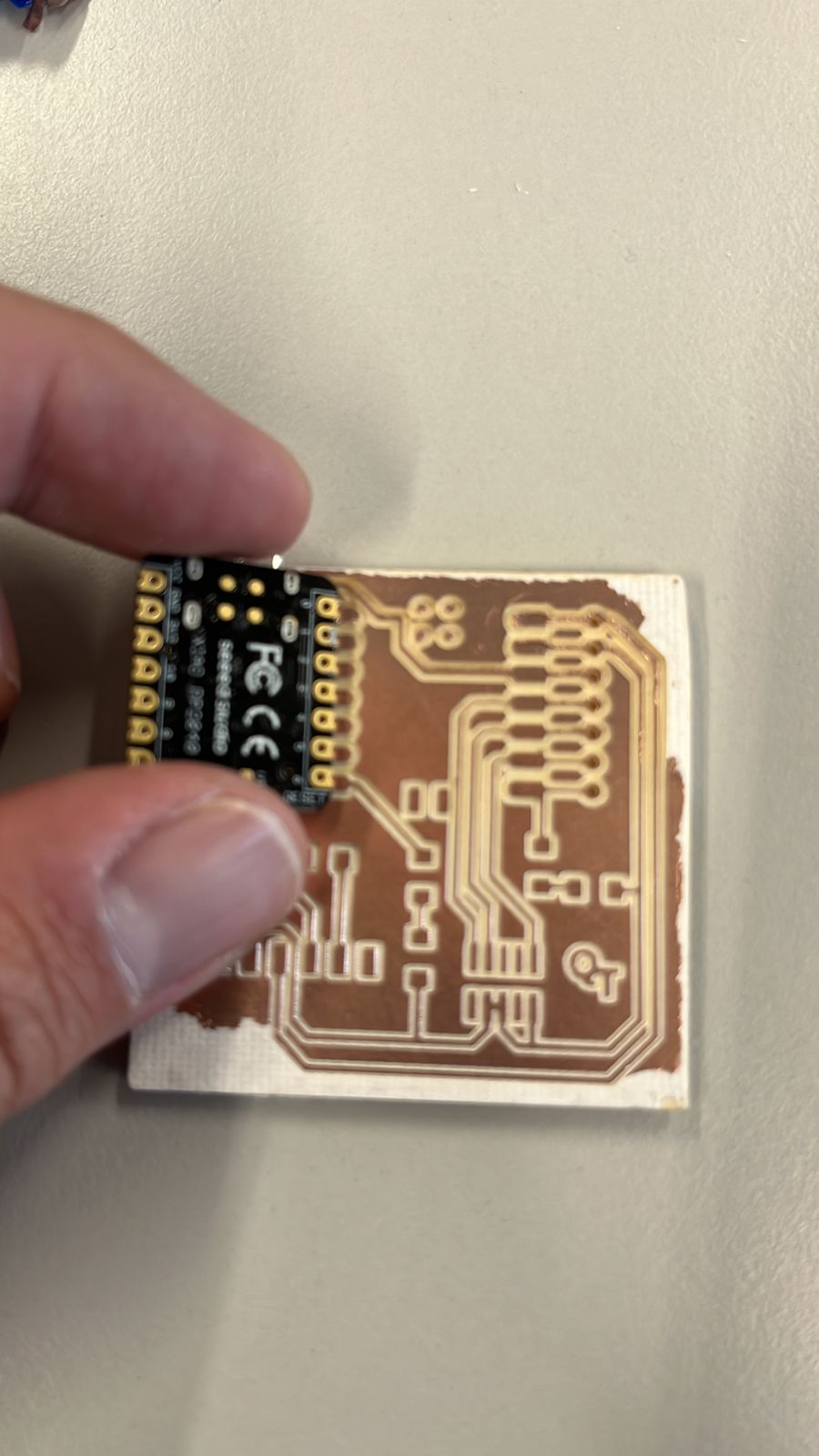
My first steps were to motivate myself that I could do it. So, I grabbed some inspiration and started my first trials soldering harmlessly in another already failed phenolic plate. Next, you may see some images of the final work of my mate Israel and my firstharmless brushstrokes.
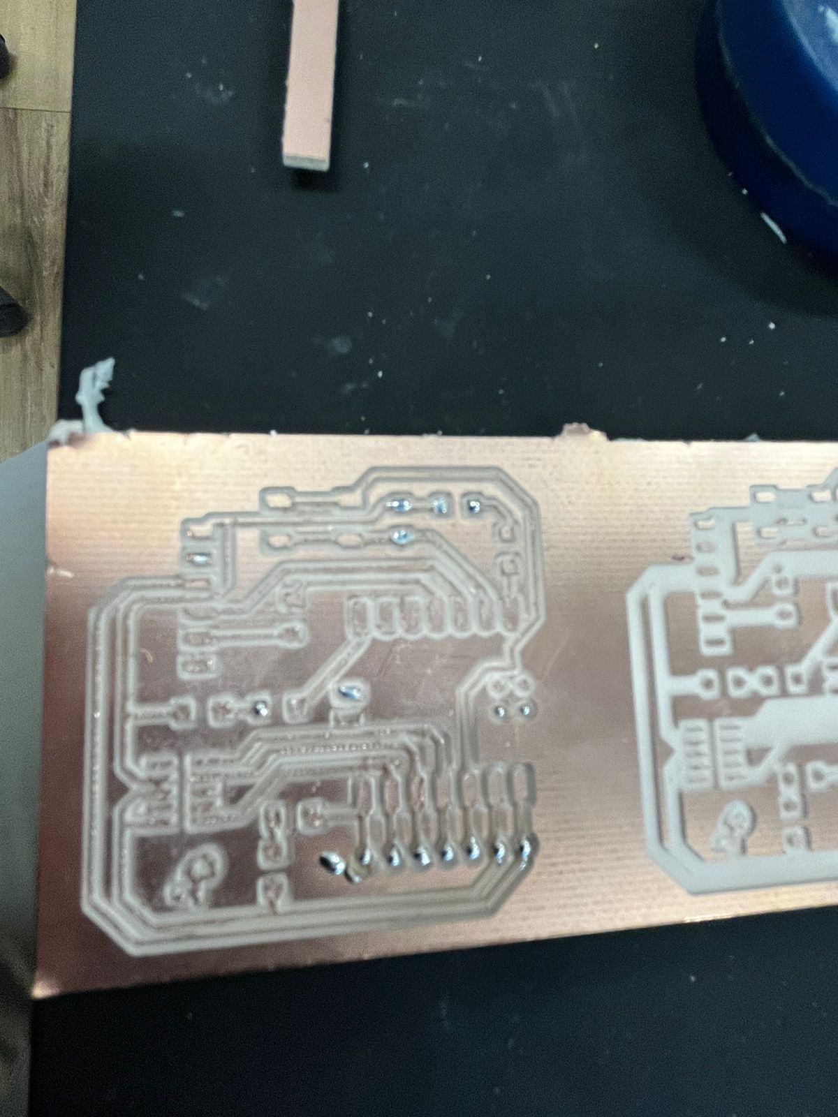
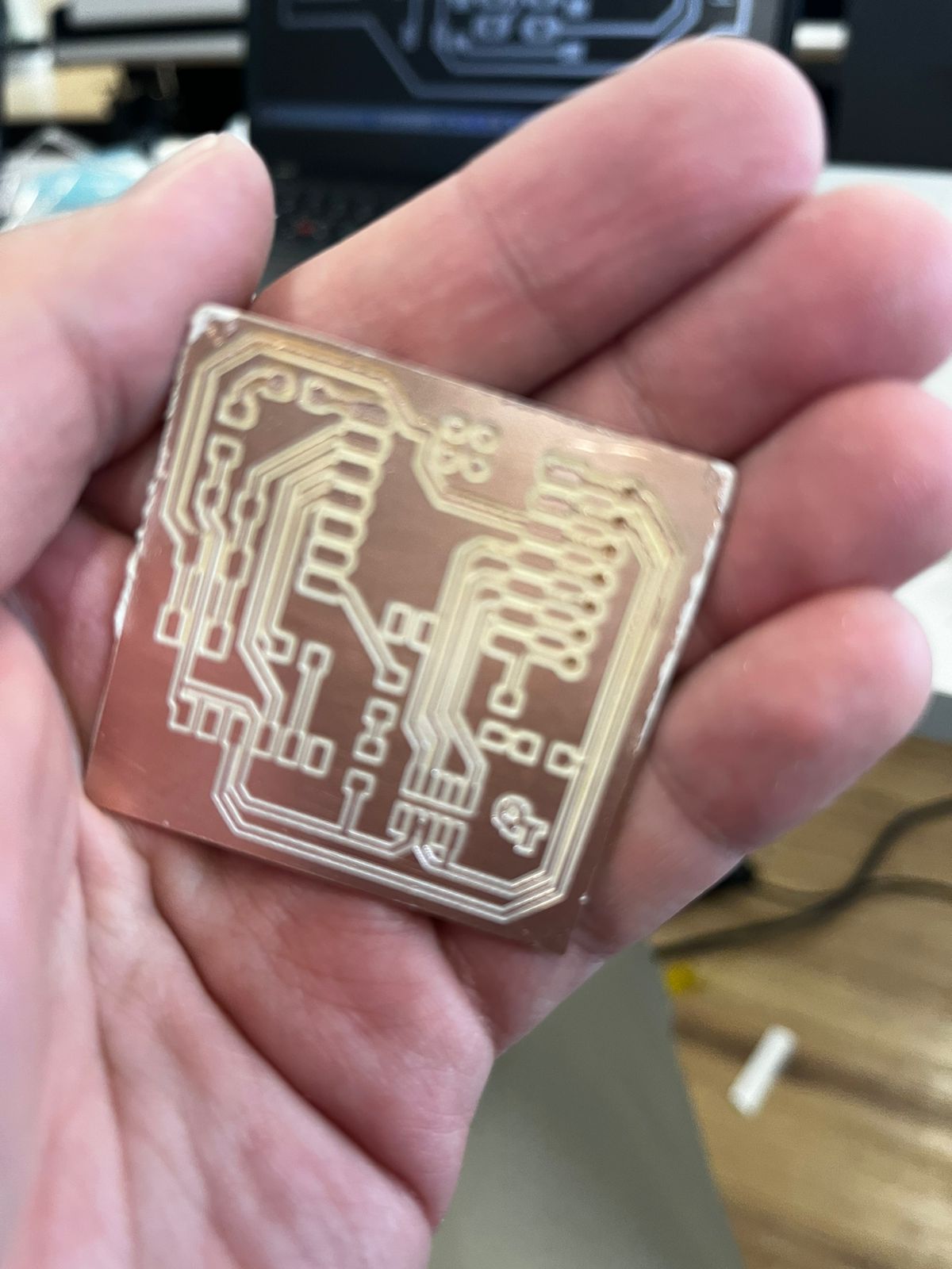
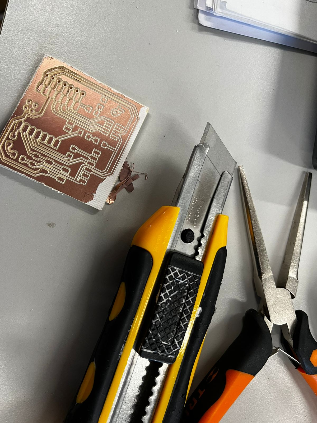
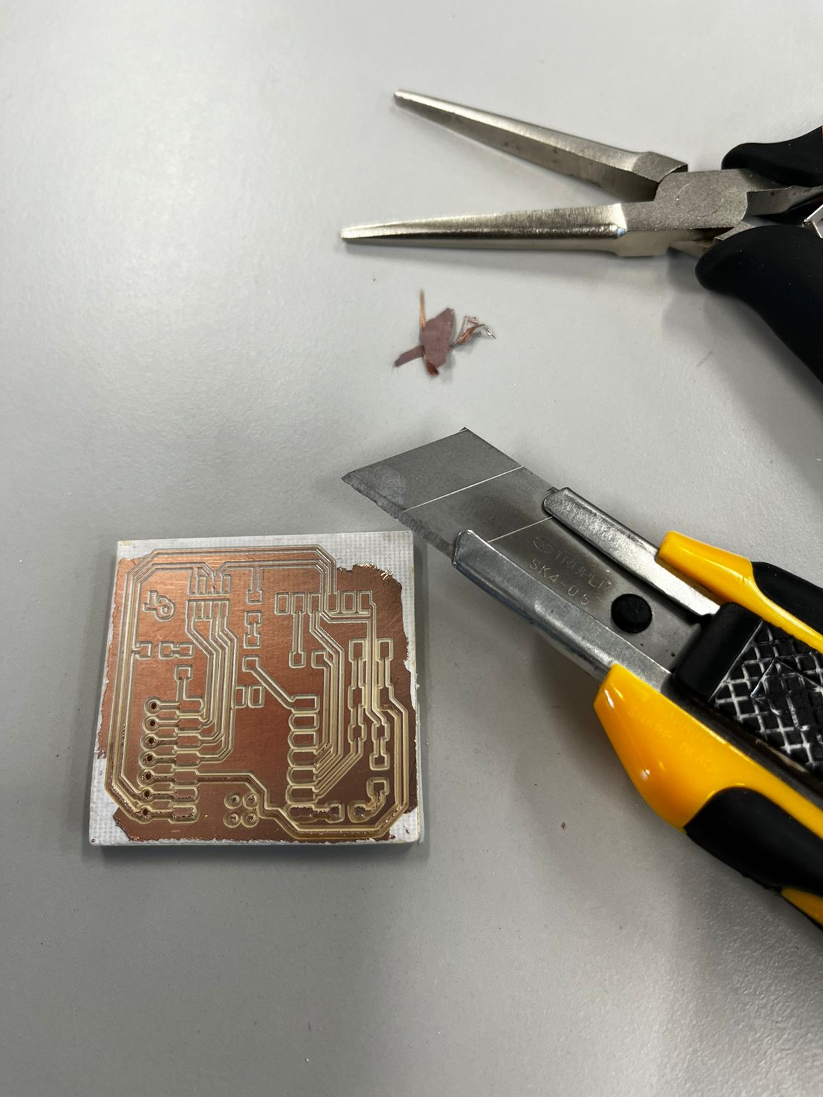
The Roland was set to trim just to a certain point, I decided (considering my teammates experience) to manually continue the trimming of the plate. Next, I share some pictures of different grades of advancement and the tools I used to do it:
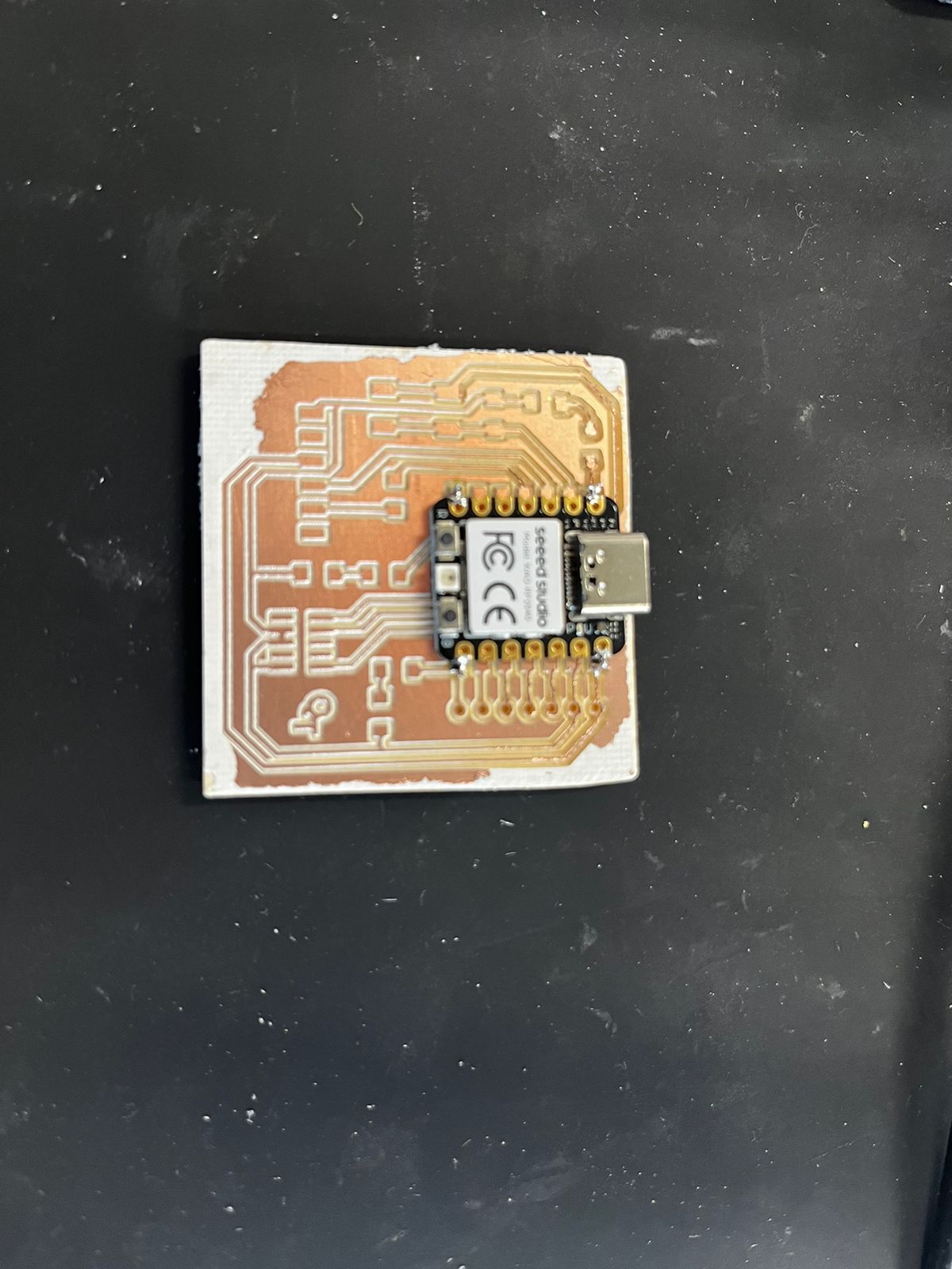
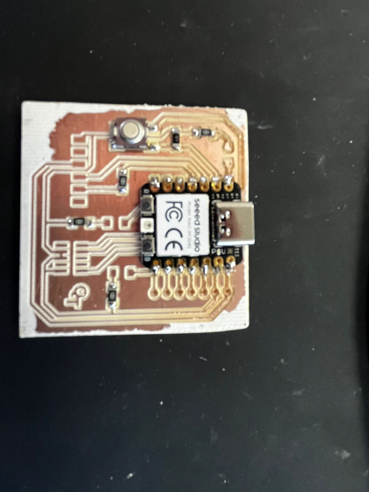
It was really challenging to solder the components, some of them meassure in nanomilimeters. I realized why such an industry has been developed as now some factories are able to produce them in speed record with ultra precise machines. Remember to set the soldering iron´s temperature to 300°C and to check that the endpoint is sharp, especially if -like me- your pulse is useful to throw sugar to the churros. A good technique, provided by my advisor Luis, is the waltz: 1,2,3 soldering iron...1,2,3 soldering weld...1,2,3 weld out...1,2,3 iron out.
The tools I used to trim the phenolic plate:
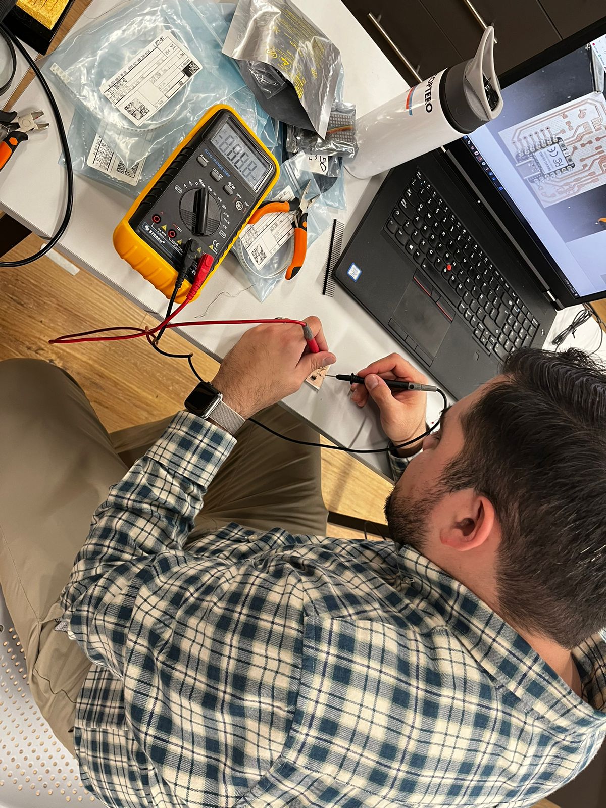
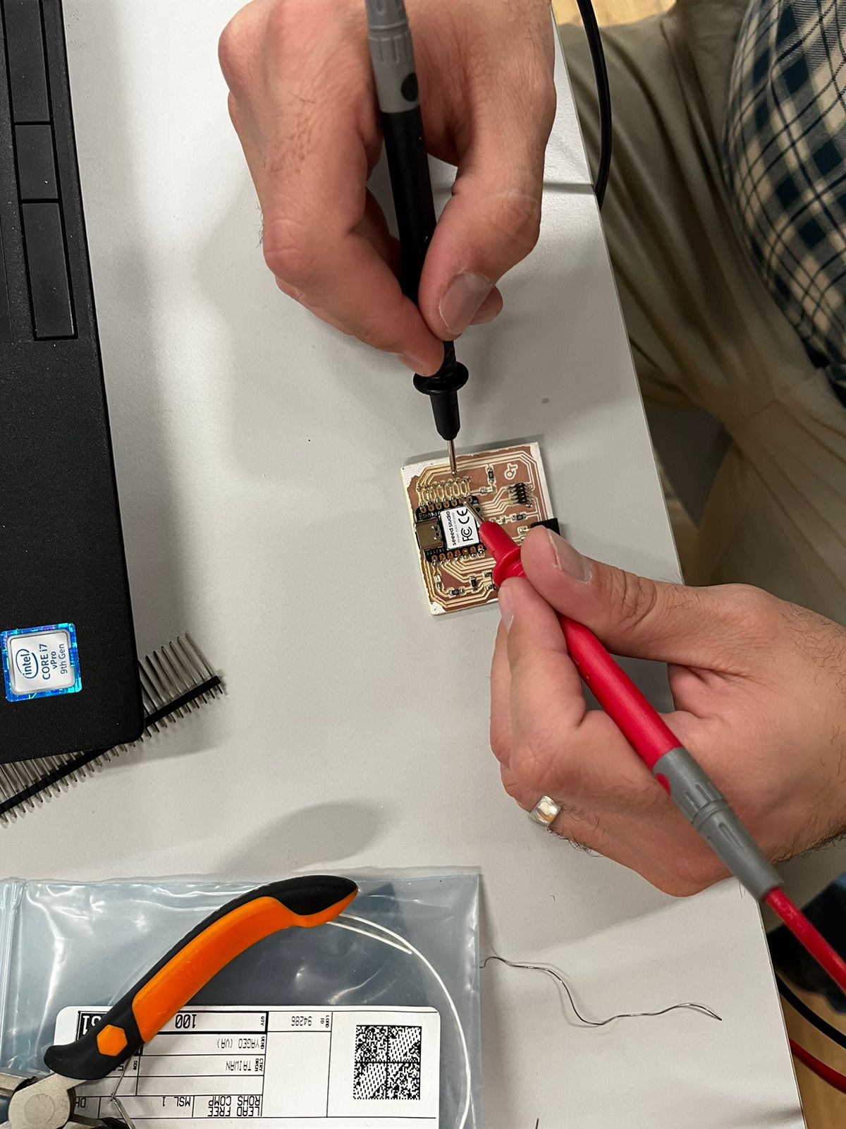
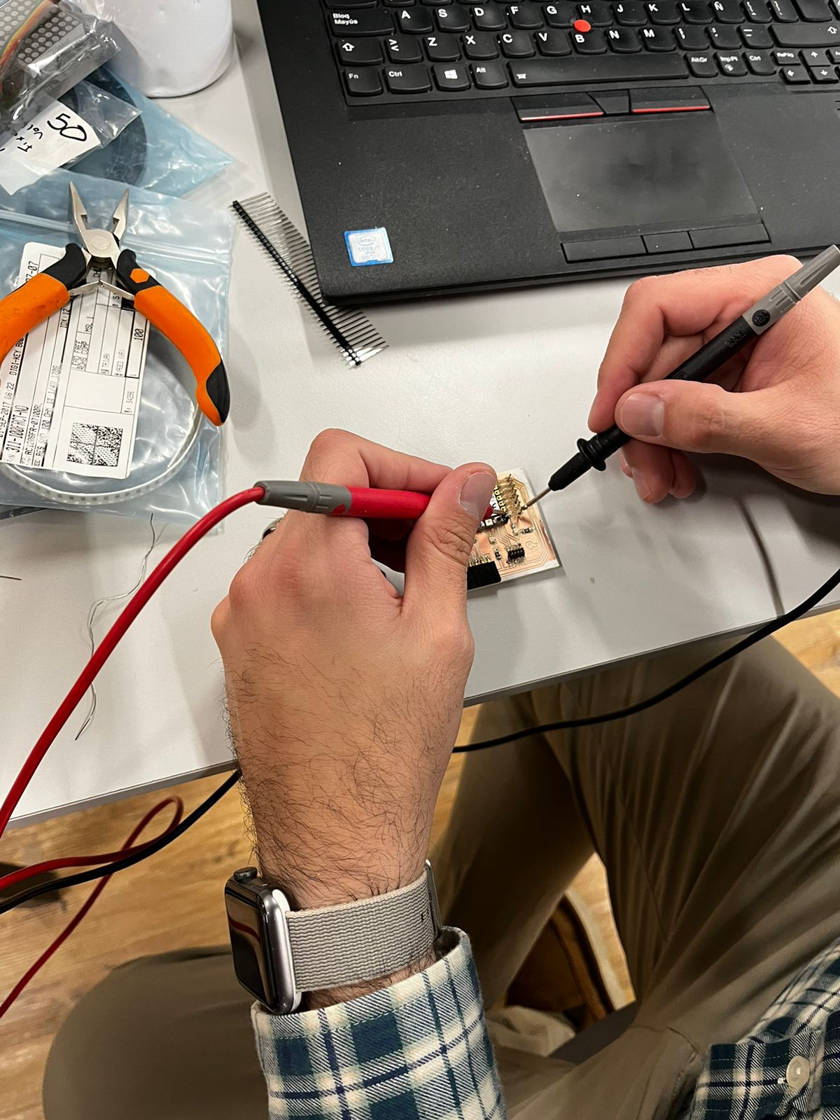
Also, here I share some evidence of me checking with a multimeter that connections are not lost:
Programming
To verify that the practice was succesful, it ws now time to pass the test: the microcontroller development board needed to perform what I set on a program.
I consulted the basics on Arduino IDE programming for the XIAO RP2040 board, here.Then I set the following configuration, again inspired by my colleague Israel:
// Rogelio Cordoba 19/02/24
int Led1=0, Led2=1, Led3=7;
// the setup function runs once when you press reset or power the board
void setup() {
// initialize digital pin LED_BUILTIN as an output.
pinMode(Led1, OUTPUT);
pinMode(Led2, OUTPUT);
pinMode(Led3, OUTPUT);
}
// the loop function runs over and over again forever
void loop() {
digitalWrite(Led1, HIGH);
digitalWrite(Led2, HIGH);
digitalWrite(Led3, HIGH); // turn the LED on (HIGH is the voltage level)
delay(1000); // wait for a second
digitalWrite(Led1, LOW);
digitalWrite(Led2, LOW);
digitalWrite(Led3, LOW); // turn the LED off by making the voltage LOW
delay(1000); // wait for a second
}
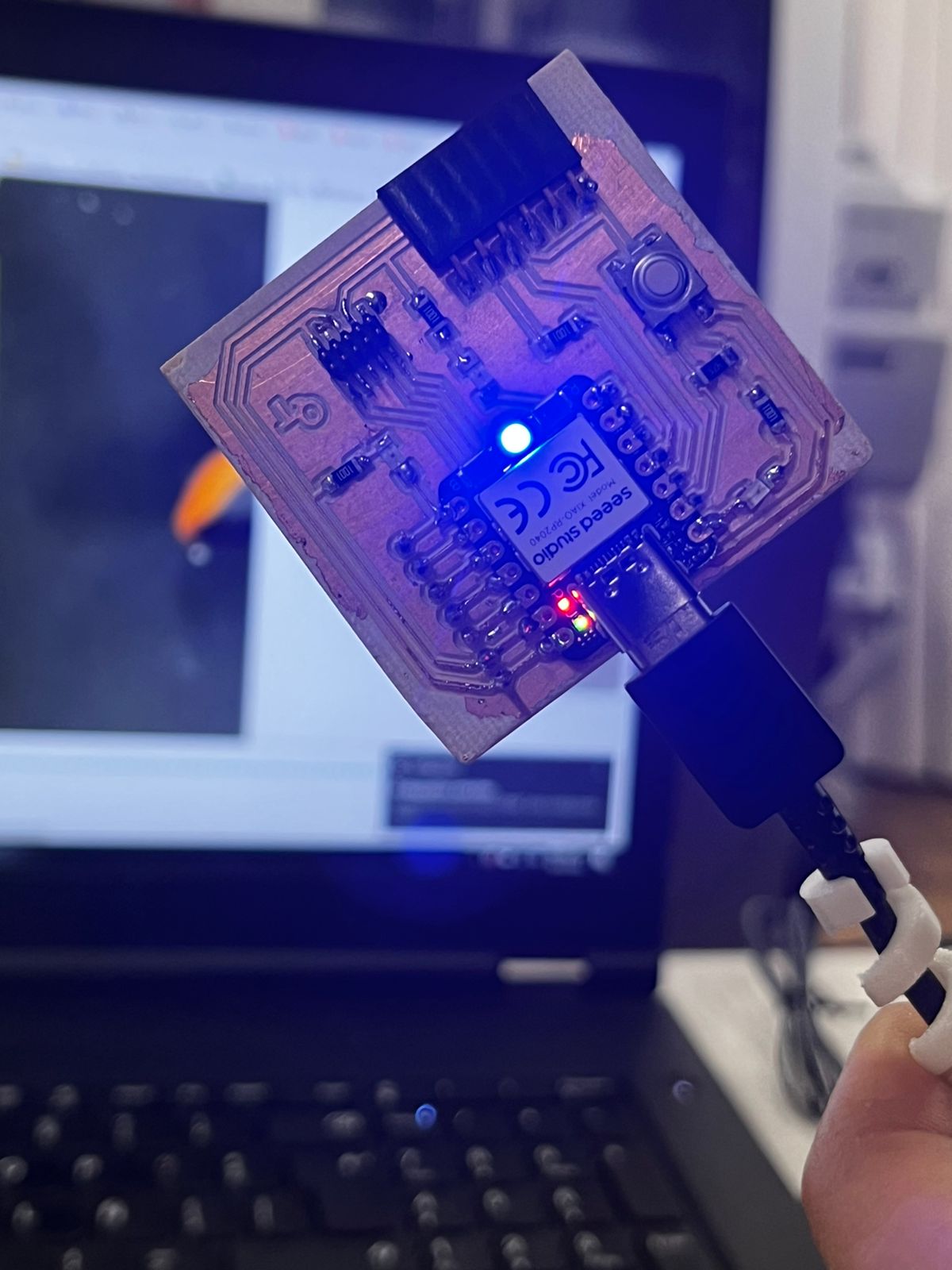
Here, you may see some evidence of the microcontroller working:
Final Comments
I made a little upgrade to my phenolic plate. I covered it with nail polish to protect the fragile copper
I also ordered a C to USB cable, to not depend on anybody else´s availability to lend it to me.
I also got some evidence of that: