Embedded Programming
Here its our group assigment: Week 6What I learned from the group assigment:
-
Arquitecture
- Are the fundamental design and structure of microcontrollers, determining how they process information. Comparison of MCUs:
- Factors for Selection:Functions needed (Bluetooth, USB, etc.), dimensions for project compatibility and performance differences among architectures. Arithmetic Operations:
- 8-bit: Limited to 0-255, -127 to 128 for negative values.
- 32-bit: Supports large numbers, over 4 billion for unsigned numbers. Common Syntax Rules:
- Python: Dynamically typed variables.
- C++: Explicitly declared variables. Control Structures:
- Python: Readable, indented block scopes.
- C++: Brace-defined scopes, supports complex control flow. Basic GPIO Commands:
- Initialization: Setting up pins as input or output.
- Reading: Checking signals received by a pin.
- Writing: Sending messages through output pins. Analog Readings:
- Measuring smoothly varying values, unlike digital signals. Timers:
- Used for managing code execution timing.
- Operate in various modes for different applications. Printing:
- Used for sending messages to a computer over USB.
- Essential for debugging and displaying sensor readings. PWM (Pulse Width Modulation):
- Mimics in-between states by rapidly turning on and off. Interrupts:
- Quick pauses in code execution to respond to immediate needs.
- Efficient way to handle external events without constant checking.
Configurate the board
You sould take in to account the proper specifications of every PCB you do, in this case I took into account the following things:
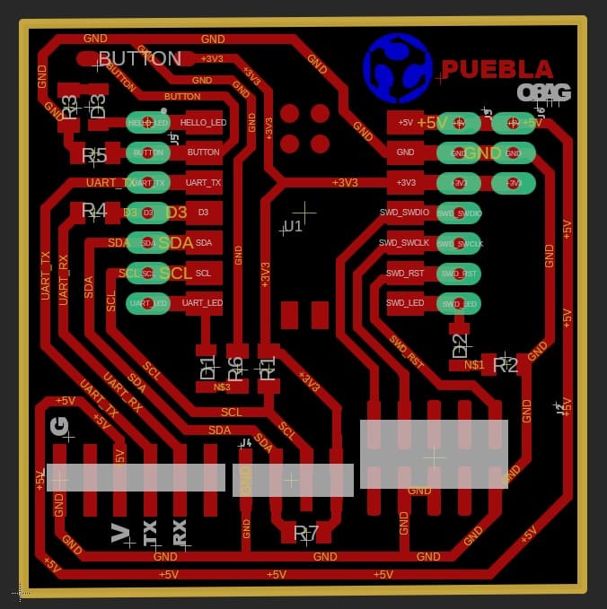
PCB design
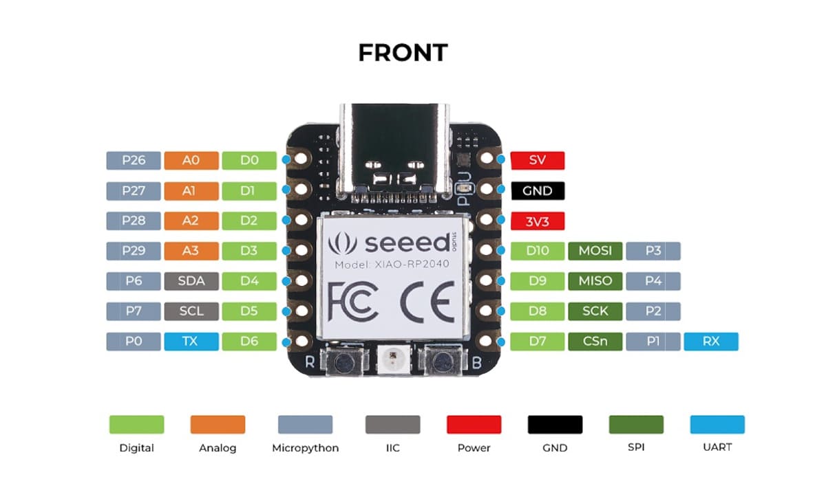
PinOut of the XIAO-RP2040
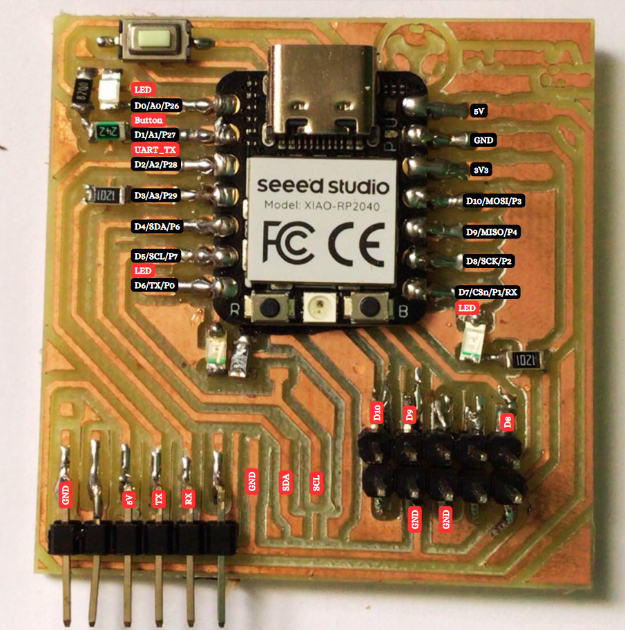
Connections on the PCB
The RP2040 chip, which is at the heart of the XIAO board, is designed to support multiple programming languages and environments.
The board is commonly programmed using the C/C++ language, thanks to the support provided by the Raspberry Pi Pico SDK.
Additionally, MicroPython and CircuitPython are alternative languages that are well-suited for the XIAO RP2040.
Regardless of the programming language chosen, you need to ensure compatibility with the RP2040 specifications and interfaces.Depending on the language choosen, everytime you want to program you should:
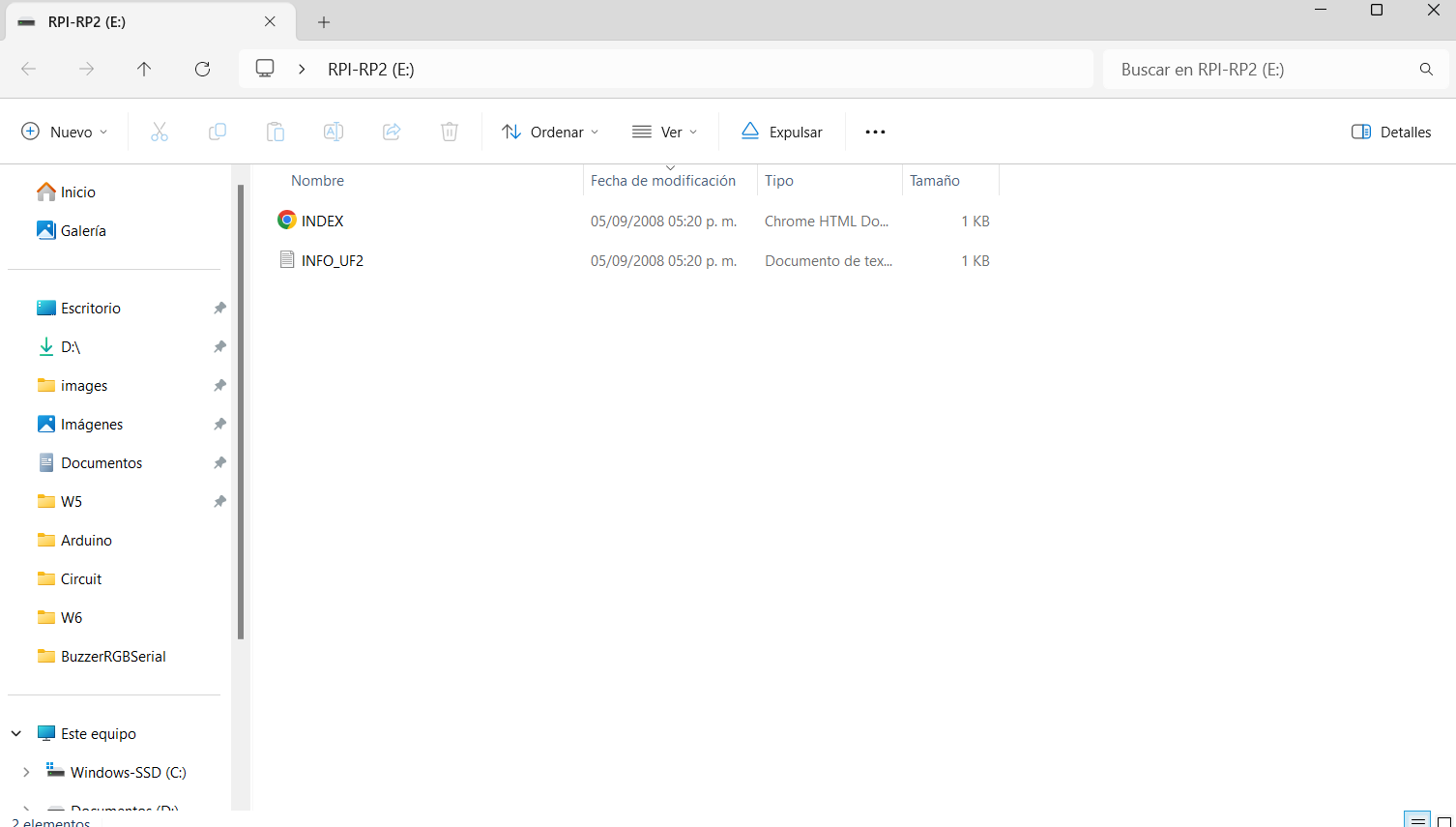
- Press the button that has an "R" of reset:
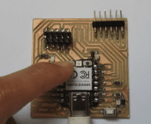
- While pressing that button, connect it to your computer:
- It should appear something like this:

For programming on Arduino, you should follow this steps:
-
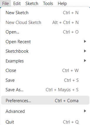
Click on "File",, so you can oppen the tab of preferences:
-
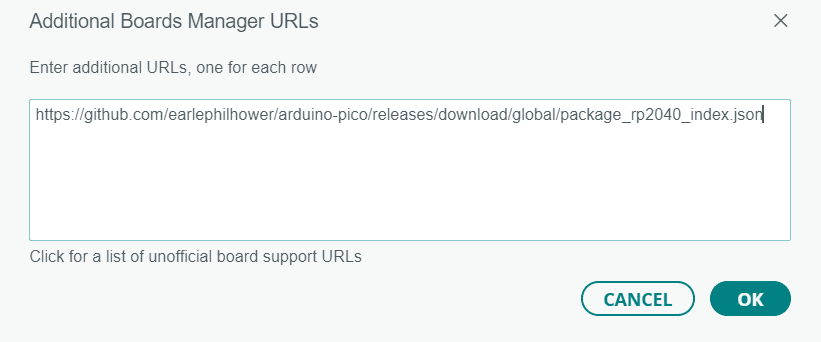
Then on "Additional boards manager, you should paste the following URL: //github.com/earlephilhower/arduino-pico/releases/download/global/package_rp2040_index.json
-
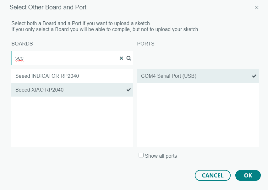
After everything download properly, on you should look for something like this:
-
Down below should appear that he port is correctly connected

-
Then when you finish you code, you just click on compilation button and it should appear "Done uploading"


For programming on CircuitPython, you should follow this steps:
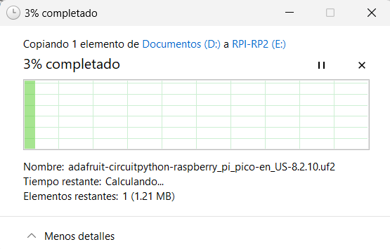
- Dowload the following document: CircuitPython UF2
-
It should be a document like this:

-
The you should reset the RM2040 and on the folder that opens, you should paste the document:
-
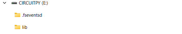
After doing that, it should appear a new folder calles "CIRCUITPY"
- Then you can freely open MU editor, so you can code on Python.
Programming
I will colocate both codes, at the left side is goint to be the c code and on the right side is the pyhton code; for all the codes I made.
Some codes can be quite lengthy, so I recommend downloading the file for easier comparison. In this case, I've only included it here to showcase the differences between the two code types.
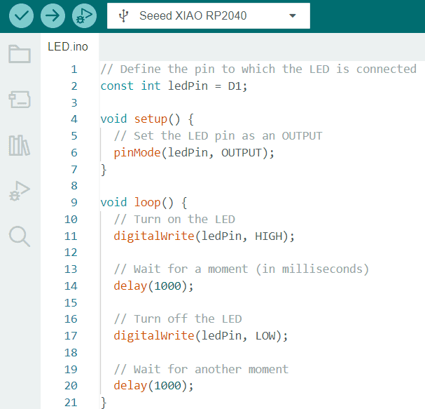
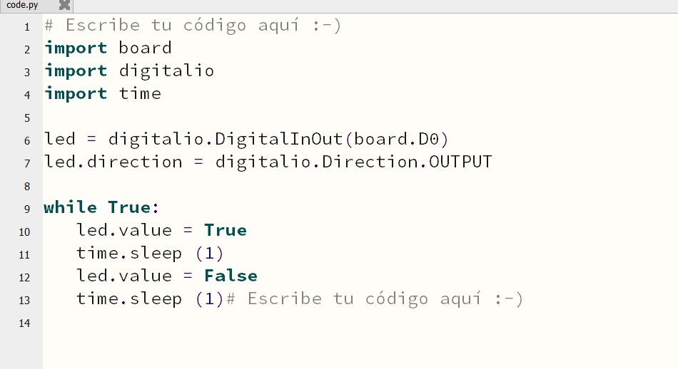
Turning on and off a LED
This code controls an LED connected to pin D0. In the setup function, the code configures D0 as an OUTPUT pin. The main loop repeatedly turns on the LED by setting the pin's output to HIGH, waits for a second using the delay function, turns off the LED by setting the pin's output to LOW, and then waits for another second. This results in a simple blinking effect where the LED alternates between being on and off at one-second intervals.
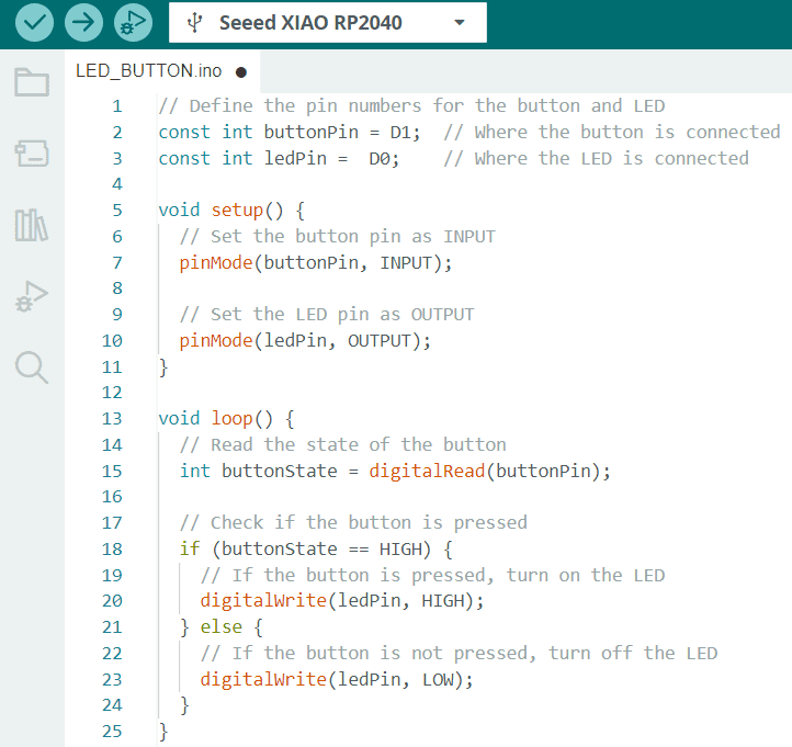
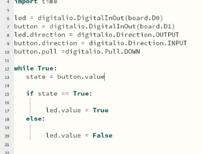
Turning on and off a LED with a button
In the setup function, D1 is an input (for reading the button state) and D0 is an output (for controlling the LED). The main loop continuously reads the state of the button using digitalRead on pin D1. If the button is pressed (its state is HIGH), it turns on the LED by setting the output on pin D0 to HIGH; otherwise, it turns off the LED by setting the output to LOW. Essentially, this code creates a simple circuit where pressing the button toggles the LED on and off.
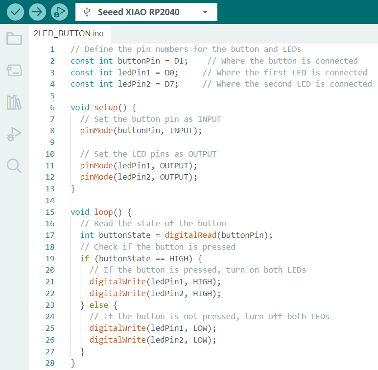
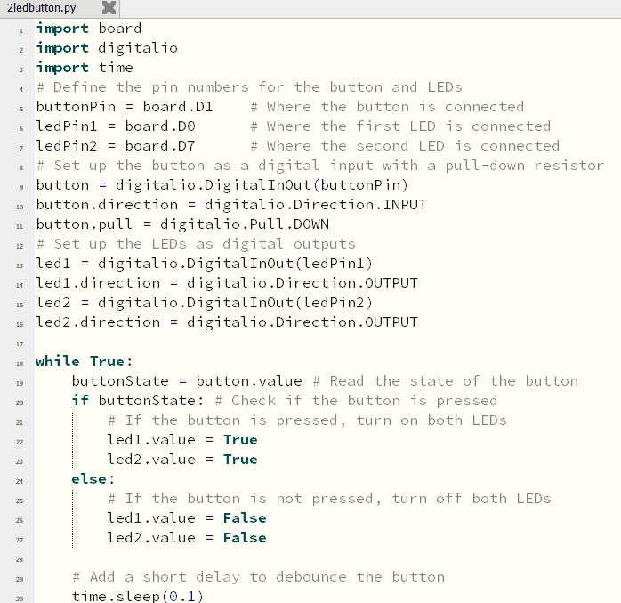
Turning on and off 2 LEDs with a button
In the setup function, the button pin is configured as INPUT, and the LED pins are configured as OUTPUT. In the loop function, the code continuously reads the state of the button using digitalRead(). If the button is pressed (buttonState is HIGH), both LEDs are turned on using digitalWrite(). If the button is not pressed, both LEDs are turned off. Essentially, this code creates a simple circuit where pressing the button activates both LEDs, and releasing the button turns them off.
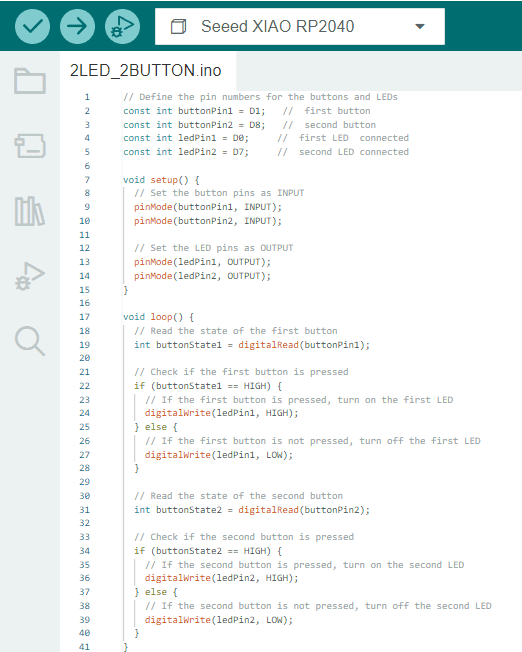
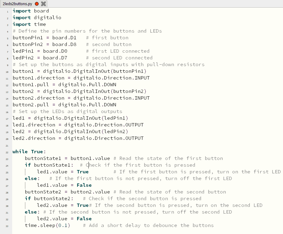
Turning on and off 2 LEDs with 2 buttons
In the setup function, the button pins are configured as INPUT, and the LED pins are configured as OUTPUT. In the loop function, it continuously reads the state of the first button and, if pressed (HIGH), turns on the first LED; otherwise, it turns it off. The same process is repeated for the second button and LED. Essentially, this code creates a simple circuit where pressing each button lights up the respective LED.
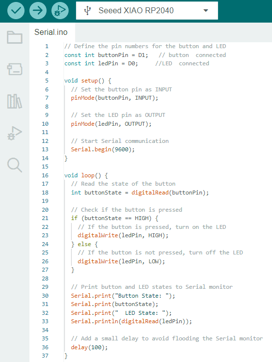
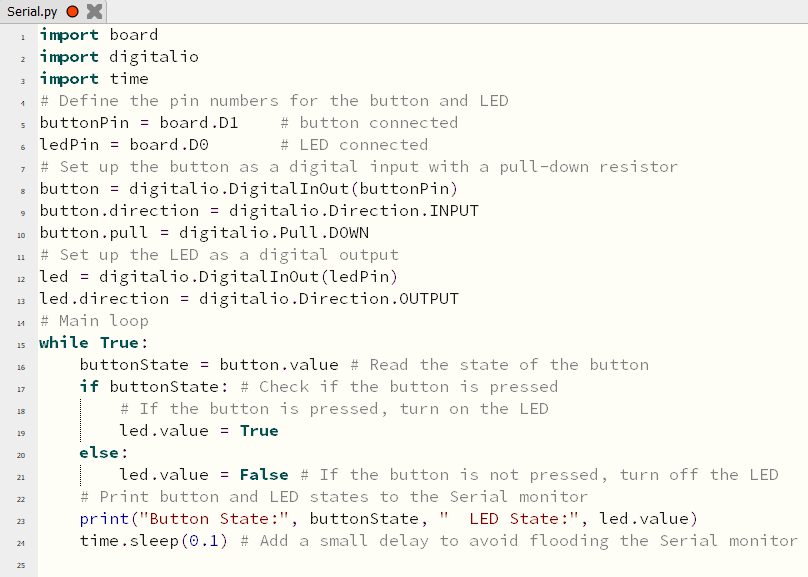
Serial
In the setup function, the button pin is configured as INPUT, and the LED pin is set as OUTPUT. Serial communication is initiated at a baud rate of 9600. The main loop continuously reads the state of the button using digitalRead and checks if it's pressed. If the button is pressed (HIGH state), the LED is turned on (HIGH state); otherwise, the LED is turned off (LOW state). The code also prints the current state of the button and the LED to the Serial monitor, providing real-time feedback. Additionally, a small delay of 100 milliseconds is added to prevent overwhelming the Serial monitor with rapid updates.
Buzzer
A buzzer is often considered a direct connection because it is a straightforward electronic component that typically requires a simple electrical connection to operate.
Usually has two leads (positive and negative) that need to be connected to a power source for it to produce sound.
The sounds of the following videos, are quite high because of the buzzer, please be careful while listening.
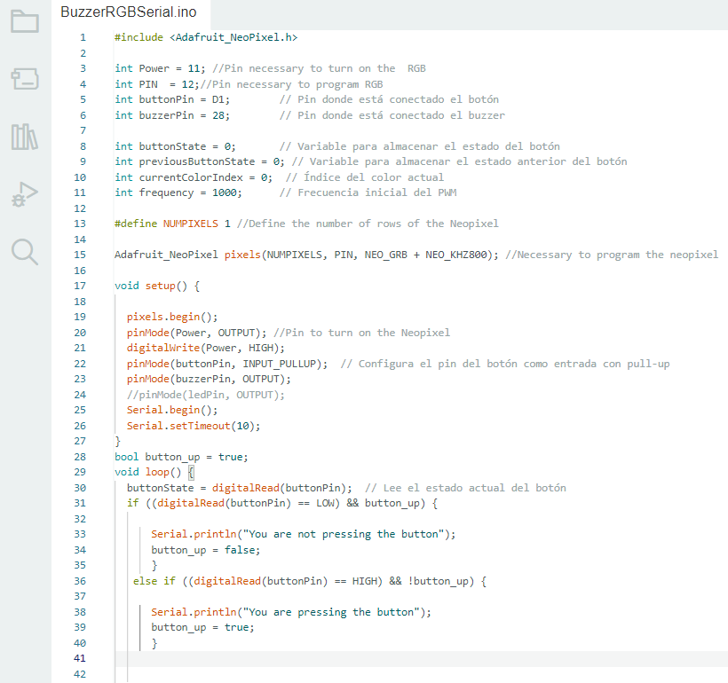
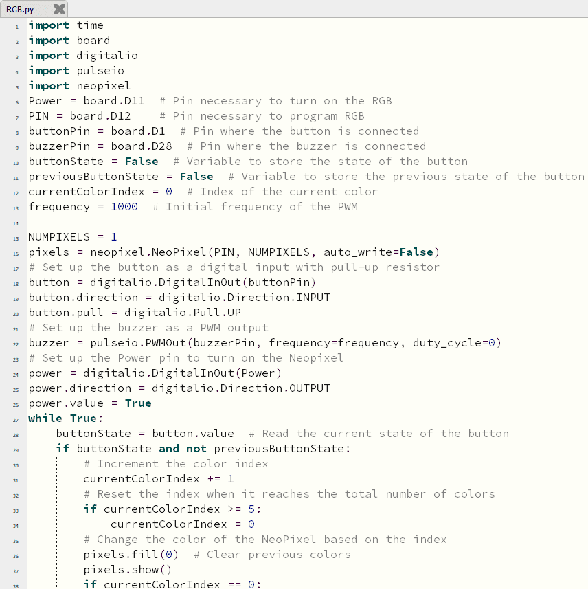
Changing colors of an RGB LED and the PWM of a buzzer with a button
This code utilizes the Adafruit NeoPixel library to control a single NeoPixel RGB LED. The program is designed to change the LED color each time a button is pressed, while also generating a changing tone on a buzzer. The NeoPixel is connected to pin 12, and the power to the NeoPixel is controlled by pin 11
The loop continuously checks the button state and, upon detecting a button press, increments the color index. The program then sets the NeoPixel color based on the current color index, plays a tone on the buzzer with a changing frequency, and waits briefly to avoid rapid changes. The available colors are blue, purple, yellow, red, and dark blue.
I put it inside the flower vase I made on Week 3, so it would look like a disco ball.
Here is how it actually works, with some few changes it can change colors and sounds automatically, but I wanted to use the button.
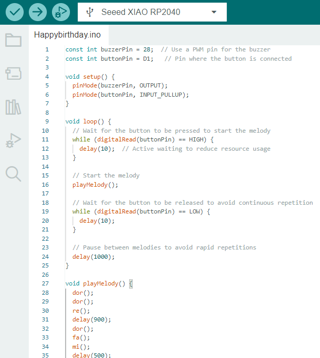
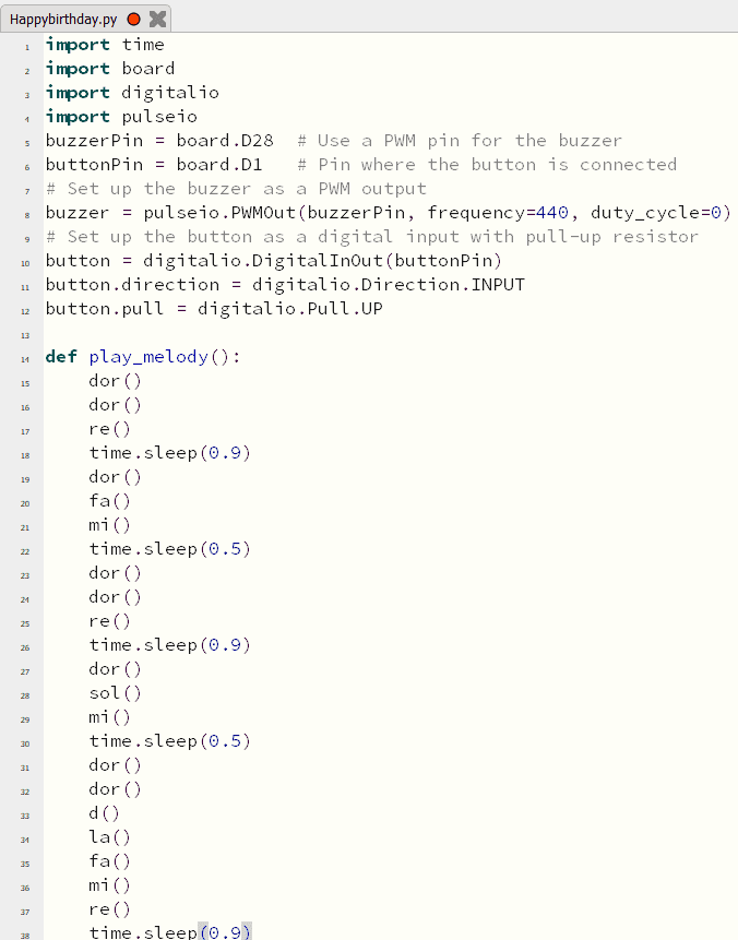
Changing PWM for the buzzer to sing happy birthday.
This code is designed to play a simple melody on a buzzer when a button is pressed.
The main loop waits for the button to be pressed, and when it's detected, it calls the playMelody function. The playMelody function plays a sequence of musical notes using the tone function, each associated with a specific frequency for the buzzer and duration. The individual note functions (dor, sol, re, mi, d, si, la, and fa) are responsible for producing the corresponding tone for a given note and duration. After playing the melody, the loop waits for the button to be released before allowing another melody to be triggered. A delay of 1000 milliseconds (1 second) is added between melodies to prevent rapid repetitions.
I couldn't take a lot of photos of me programming because I was quite concentrated in each code, but here is one :)

Documents
Arduino codes
- TURNING ON AND OFF A LED
- TURNING ON AND OFF A LED WITH A BUTTON
- TURNING ON AND OFF 2 LEDS WITH A BUTTON
- TURNING ON AND OFF 2 LEDS WITH 2 BUTTONS
- SERIAL
- CHANGING COLORS OF AN RGB LED AND THE PWM OF A BUZZER WITH A BUTTON
- CHANGING COLORS OF AN RGB LED AND THE PWM OF A BUZZER WITH A BUTTON
CircuitPython
- TURNING ON AND OFF A LED
- TURNING ON AND OFF A LED WITH A BUTTON
- TURNING ON AND OFF 2 LEDS WITH A BUTTON
- TURNING ON AND OFF 2 LEDS WITH 2 BUTTONS
- SERIAL
- CHANGING COLORS OF AN RGB LED AND THE PWM OF A BUZZER WITH A BUTTON
- CHANGING COLORS OF AN RGB LED AND THE PWM OF A BUZZER WITH A BUTTON