3D Scanning and Printing
Group assignments
Here its our group assigment: Week 5- Test the design rules for your 3D printer(s).
- Document your work on the group work page and reflect on your individual page what you learned about characteristics of your printer(s).
- In the Fablab Puebla, we have 27 3D printers, some of them are: ENDER 3 S1 PRO, SINDOH 3DWOX 1, Stratasys Dimension 1200es, ROSTOCK V3 MAX,ULTIMAKER 2+,ELEGOO MARS 3,ELEGOO SATURN 2, ANYCUBIC PHOTON M5s and FORM 2.
- There is also a huge variety of materials, such as: PLA, ABS,PETG, Nylon and TPU.
- In my opinion here are some Advantages and Limitations for 3D printing:
- 3D printing allows for intricate and complex designs that would be challenging or difficult to manufacture with traditional manufacturing methods.
- Traditional manufacturing often generates significant waste through subtractive processes, while 3D printing adds material selectively, which it minimize waste.
- 3D printing is widely used for rapid prototyping, allowing designers and engineers to quickly iterate and test their designs before mass production.
Advantages
- The range of available materials for 3D printing is continually expanding, but not all materials are useful for all applications.
- 3D printing may not be as quick as traditional manufacturing methods for large-scale production.
- The layer-by-layer nature of 3D printing can result in visible layer lines on the final product, affecting aesthetics. High-resolution printing and post-processing can mitigate this.
Limitations
- Overhang: Between 4mm and 10mm the material will start falling and losing stability.
- Pringting Angle: Angles up to 45 degrees are often manageable without supports.
- Bridging: Shorter spans typically are easier to bridge.
- Wall thickness: Thick walls can be a waste of material, while the minimun thickness can successfully printed.
- Surface Finish: It depends of the printer's resolution, the material, and post-processing techniques.
- Clearence: Adequate clearance ensures supports can be removed easily without damaging the print, typically around 0.2mm to 0.5mm.
- Infill: For mechanical stress, it is requires an infill of 50% or more, but for other type of creations, 20% is perfect.
Brief resume of the Design rules:
3D printing
Desing
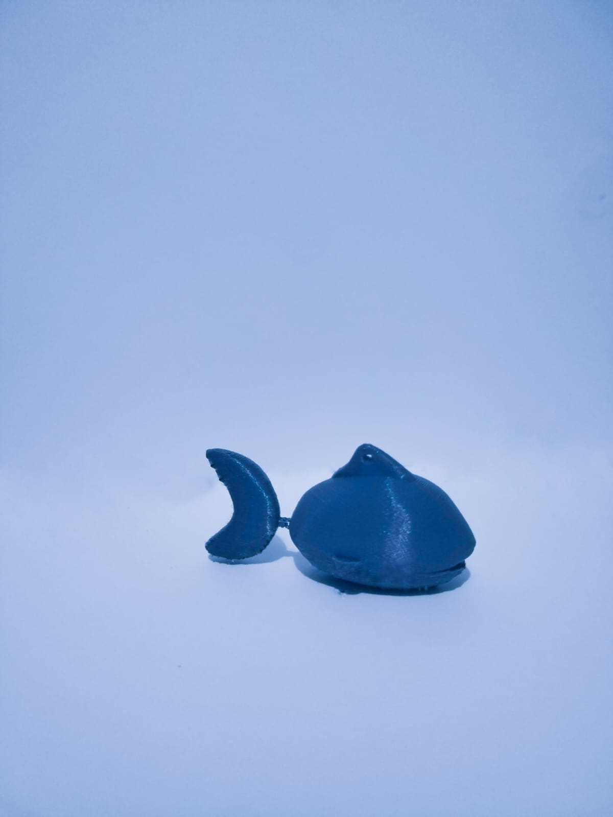
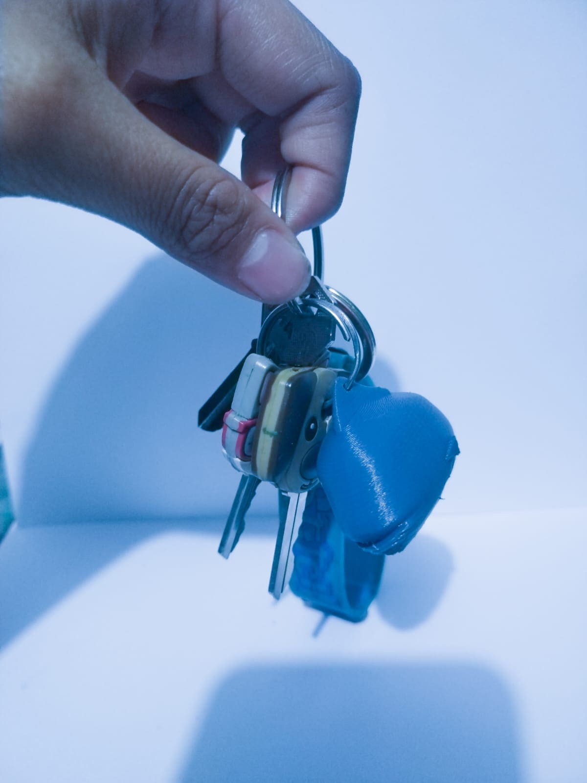
In my design, I drew inspiration from my mother's fondness for all things marine, leading me to create a fish-like structure. The intricate curves incorporated into the design are deliberately challenging to achieve with conventional machines. I included a tail with a joint seamlessly connecting it to the body, enabling fluid movement. To add practicality, I integrated a small hole designed specifically for hanging keys.
The distinction between additive and subtractive manufacturing processes lies in the fundamental approach to creating objects:
- Additive Manufacturing: Objects are created by adding material layer by layer until the final form is achieved. This method is beneficial for creating complex geometries, intricate designs, and parts with internal structures.
- Subtractive Manufacturing: Subtractive processes involve starting with a block or bulk material and removing excess material to shape the final object.
The difficulty in recreating the forms, angles, and joints of my fish using traditional subtractive manufacturing methods rather than 3D printing lies in the intricate and complex nature of these features (the joints, the tail, the fins and the body) , so it is really difficult for it to be substractive.
I would normally use SolidWorks for 3D designs, but as in this case was something with more curves and real feautures, I decided using Fusion 360. Here are the steps I followed and if you want to repeat it, you should follow:
- Launch Fusion 360.
- In the upper-right corner, click on the "Workspace" drop-down menu. Select "Sculpt" from the list of workspaces.
- Before you start sculpting, you need a base to work on. You can either create a new body or use an existing one.
- Fusion 360 offers various sculpting tools, such as "Create Form," "Edit Form," "Fill," "Drag," etc.Actually this tool was really useful to move and create textures for my fish.
- Click and drag on the geometry to deform it according to your requirements.
- On the toolbar, you'll find options to adjust the size and strength of the sculpting tool.
- Sculpting often involves subdividing the geometry for finer details. Use the subdivision tools to increase the resolution of the mesh, allowing for more intricate sculpting.
- Once you are satisfied with your sculpting work, exit the sculpting mode and return to the standard modeling workspace.
Here it is a video of the order in which I made the pieces for my fish.
Here is a screen recording of the process of how I did the tail of the fish (all the pieces were practicality made as in this video) .
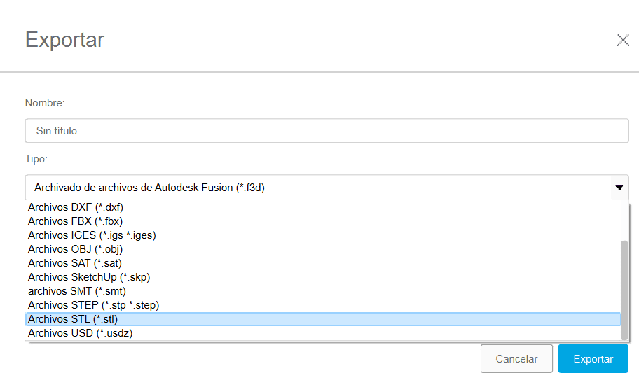
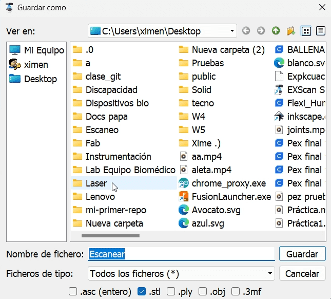
To save the document as an .stl document, you just have to change the format of exporting the document before accepting, it should look something like this:
Program to generate gcode
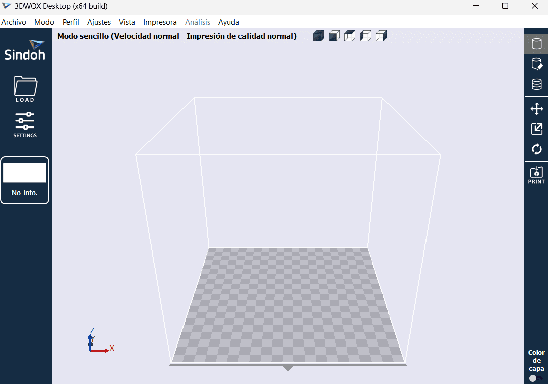
After saving the document as .stl, it is necesary to create a .gcode. As I used the 3DWOX 1 3D printer, I used their application for generating the gcode, but you can also use Quora.Here are the steps of how creating the documents:
- Download 3DWOX, from: CLICK HERE
- Open the 3DWOX application on your computer.
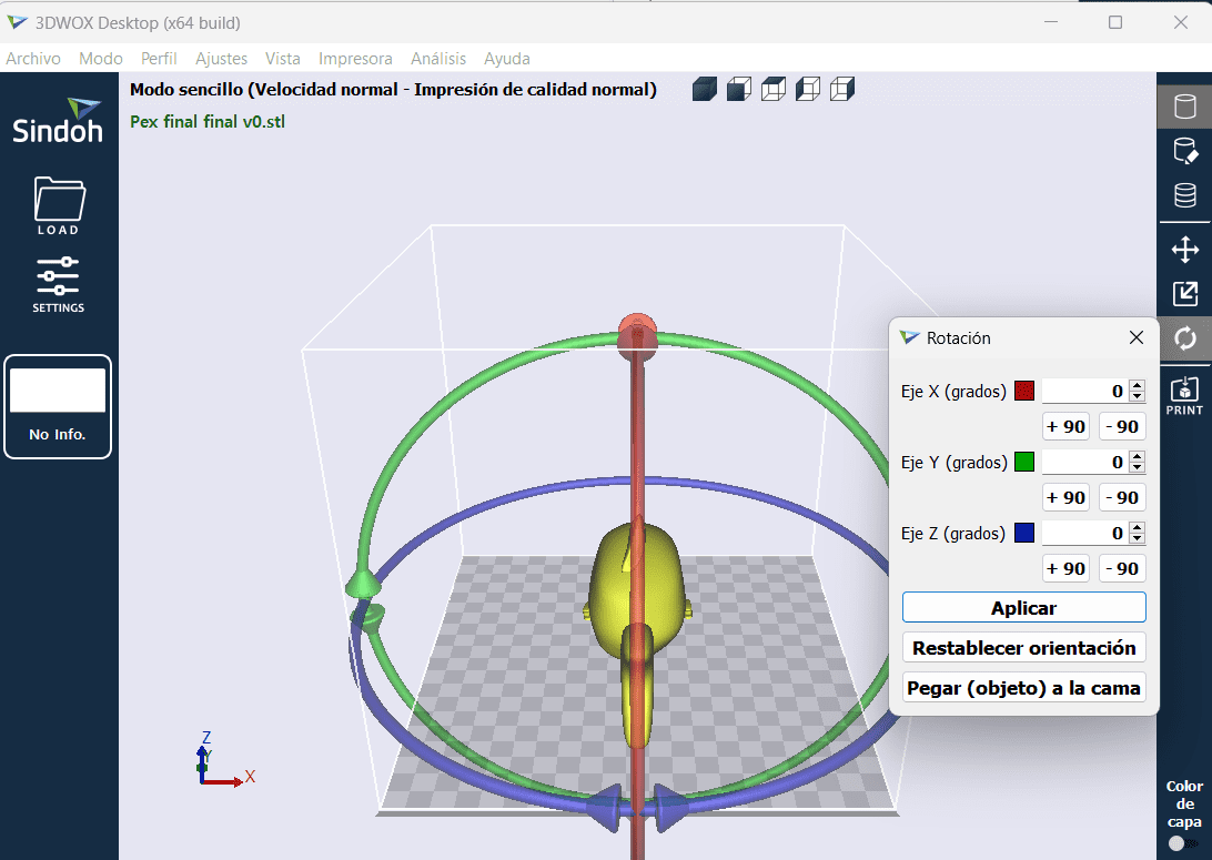
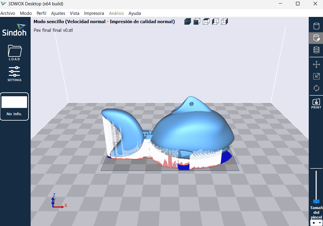
- Import the 3D model into the application. This is usually done through an "Import" or "Open" option in the software (it has to be a .stl document)
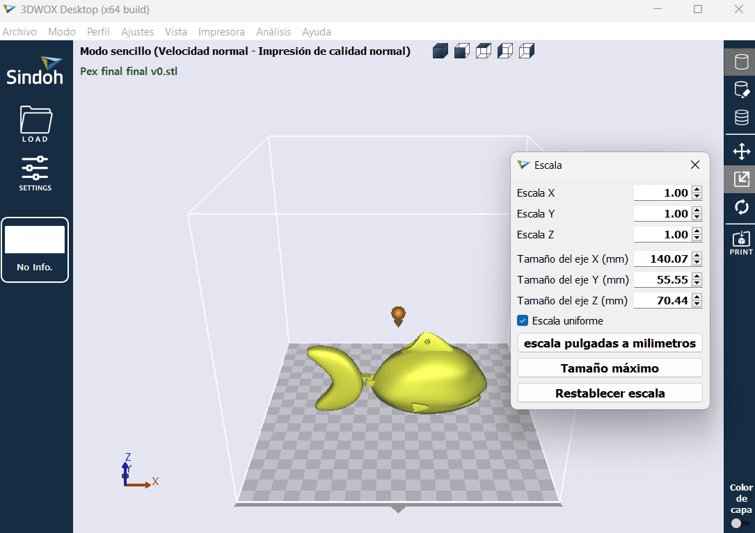
- Adjust the position and scale of your 3D model within the virtual print bed to ensure it fits properly.
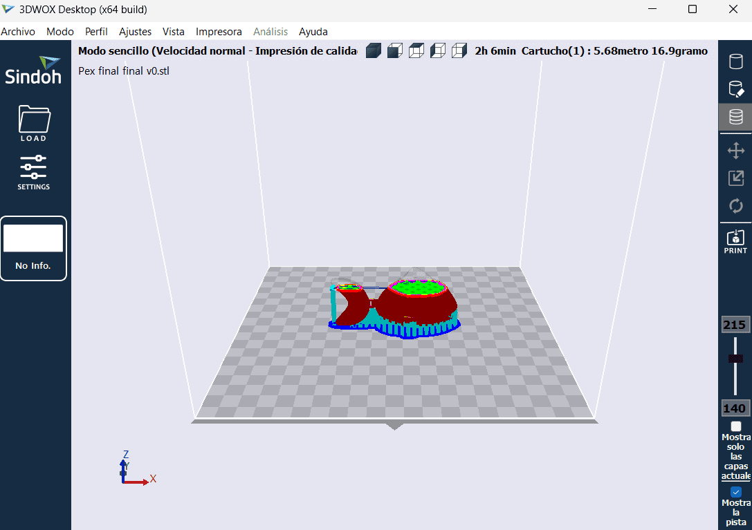
- Set various print settings such as layer height, infill density, print speed, and other parameters based on your preferences and the requirements of the 3D print.
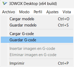
- Look for an option like "Generate G-code," "Export G-code," or a similar command in the 3DWOX application.
- Choose a location on your computer to save the generated G-code file. This file will have a ".gcode" extension.
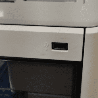
- Connect your computer to the 3D printer using a USB cable or transfer the G-code file to an SD card.

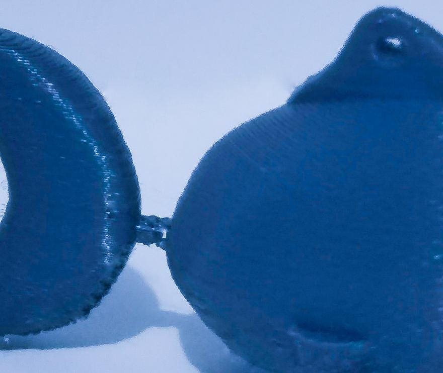
Test for joints between the tail and the fish body
I conducted a series of tests to optimize the 3D printing process for the junction between the tail and body of a fish model. The primary objectives were to find an efficient balance between material usage and ensuring the functionality of the articulated tail movement. The exploration aimed to refine dimensions, such as the outer and inner rectangle sizes, along with adjustments to the radius and material extrusion amounts. These tests were essential not only for material savings but also to validate the effectiveness of the designed mechanism for tail movement.
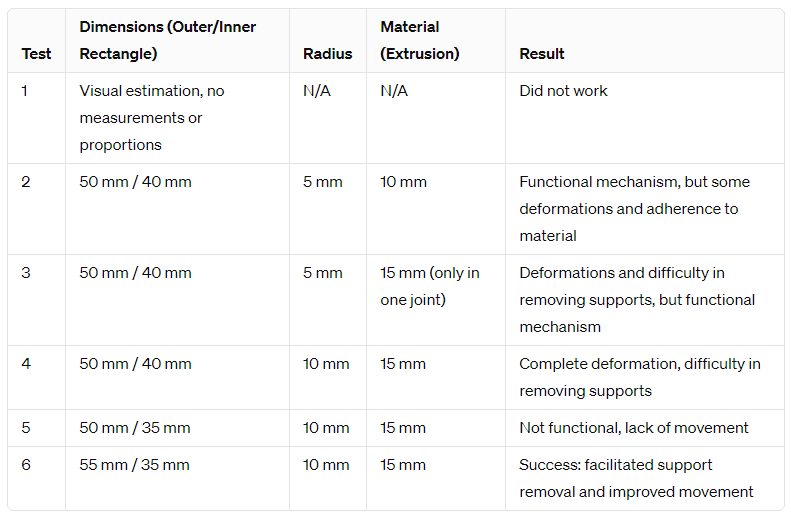
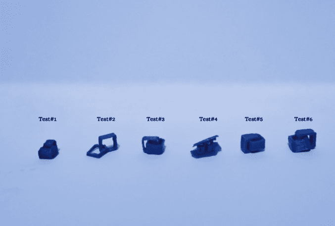
After conducting six tests, it became apparent that dimensions and proportions played a crucial role in the success of the 3D printing. The change in the size of the outer and inner rectangles in the last test proved to be crucial, providing more space for printing, easing support removal, and enhancing part mobility. The radius and the amount of material also significantly contributed, as adjusting these parameters helped overcome deformation issues and support removal difficulties. In summary, iteration and adjustment of dimensions and printing parameters were essential to achieving a successful outcome in the 3D printing of the fish tail and body junction.
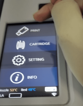
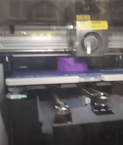
Printing
- Turn on the 3D printer.
- Colocate your usb
- Select the file
- Click play, so it starts printing
Results
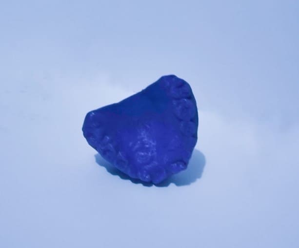
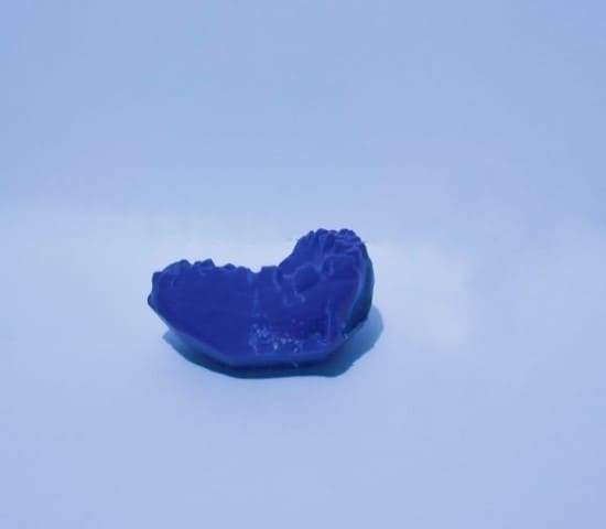
Scanning
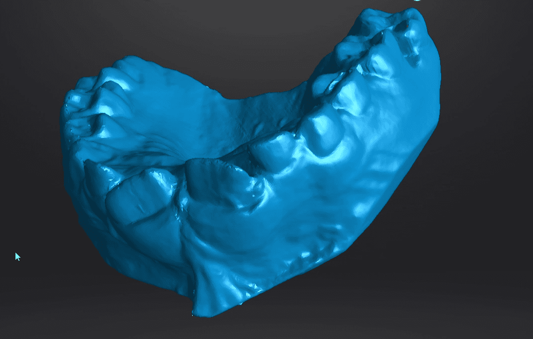
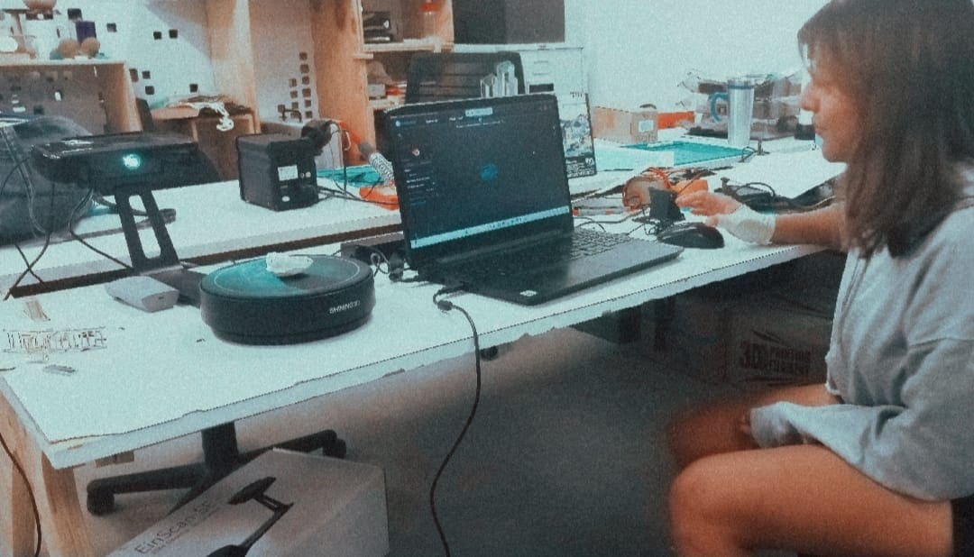
I undertook the endeavor of 3D printing a dental mold due to the current high costs associated with dental scanners. Recognizing the financial constraints faced by dentists in acquiring advanced scanning equipment, I aimed to explore a cost-effective alternative. The idea was to leverage 3D printing technology to create a mold of teeth, allowing for a more accessible and affordable solution in dental practices
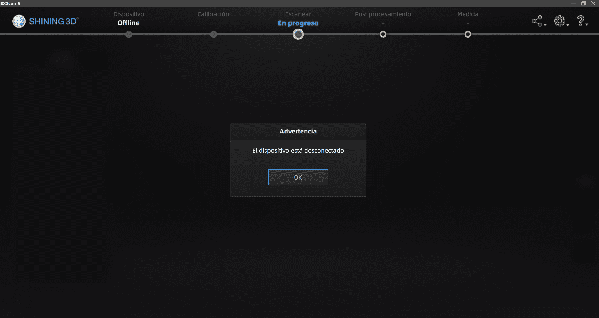
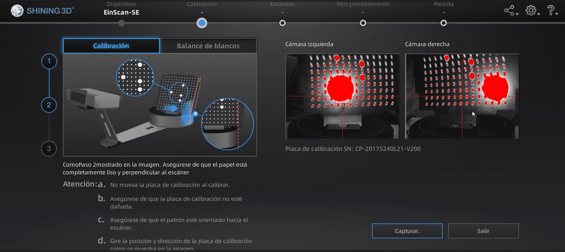
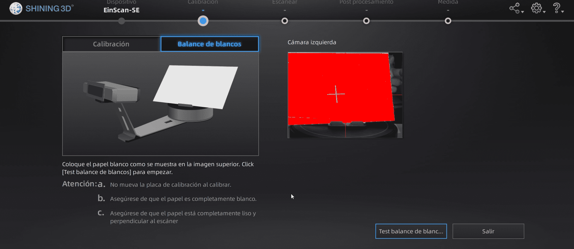
I used the EXScan for scanning my mold. Here are the steps:
-
Scanner Setup:
- Ensure that the scanner is correctly connected to power and your computer.
- Install the corresponding EXScan software on your computer.
-
Scanner Calibration:
- Before scanning, perform the scanner calibration process as per the manufacturer's instructions to ensure measurement accuracy.
-
Object Positioning:
- Place the object you want to scan on a stable surface. It's crucial that the object remains still during the scanning process.
-
Software Configuration:
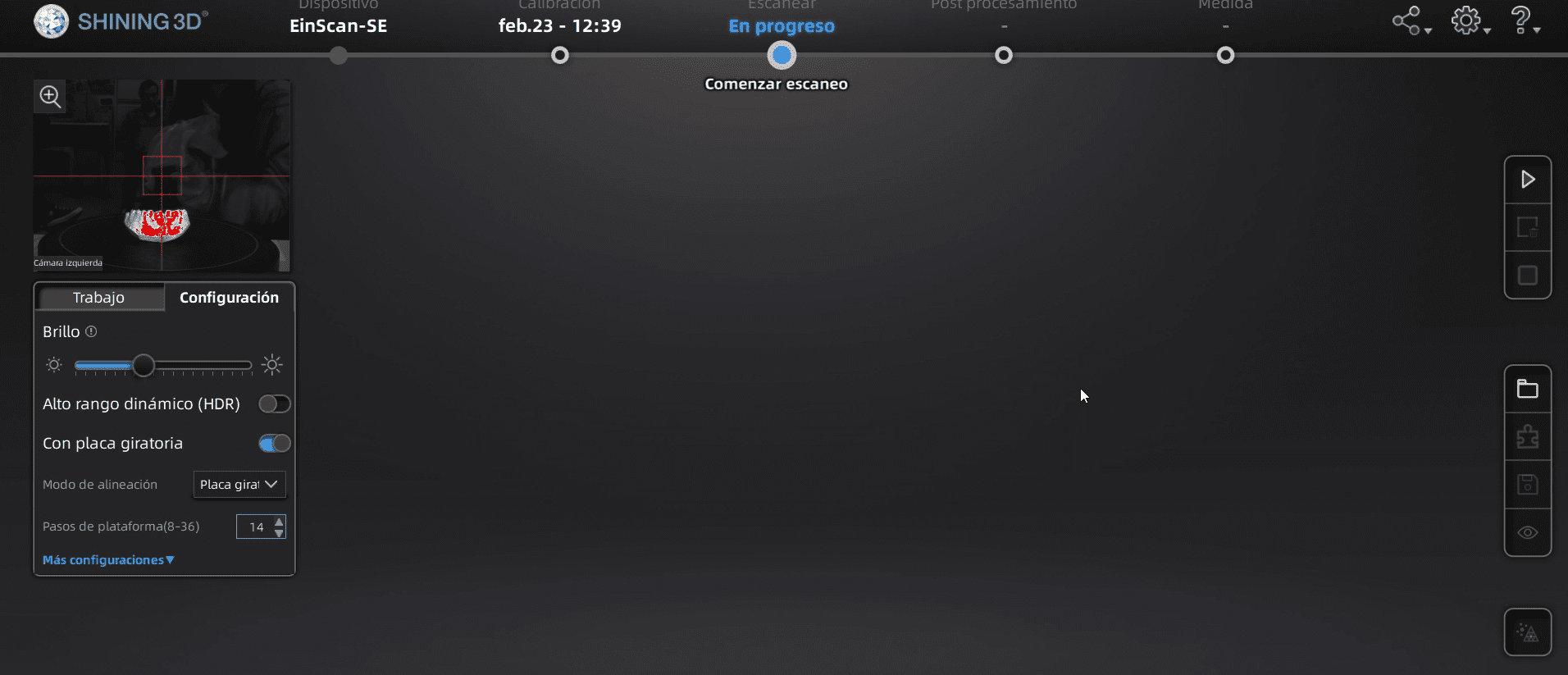
- Open the EXScan software on your computer. Configure scanning parameters, such as resolution and point density, according to your needs.
-
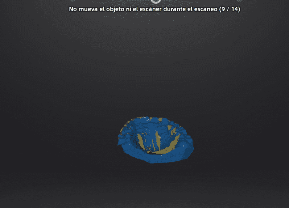
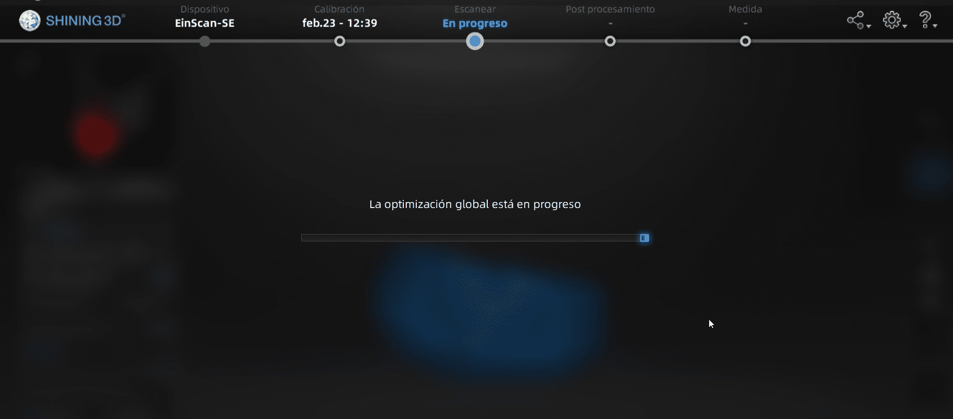
Initiate Scanning:
- Start the scanning process following the prompts in the software.
- Move the scanner around the object, ensuring you capture all surfaces and angles.
-
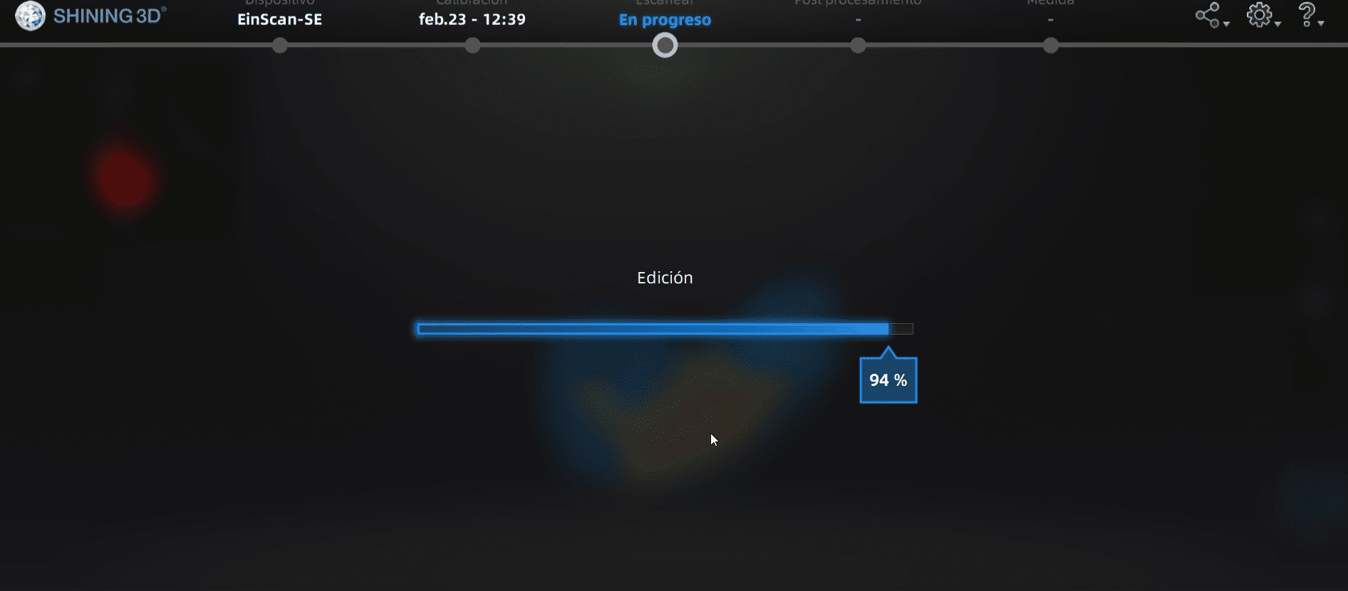
Real-time Review:
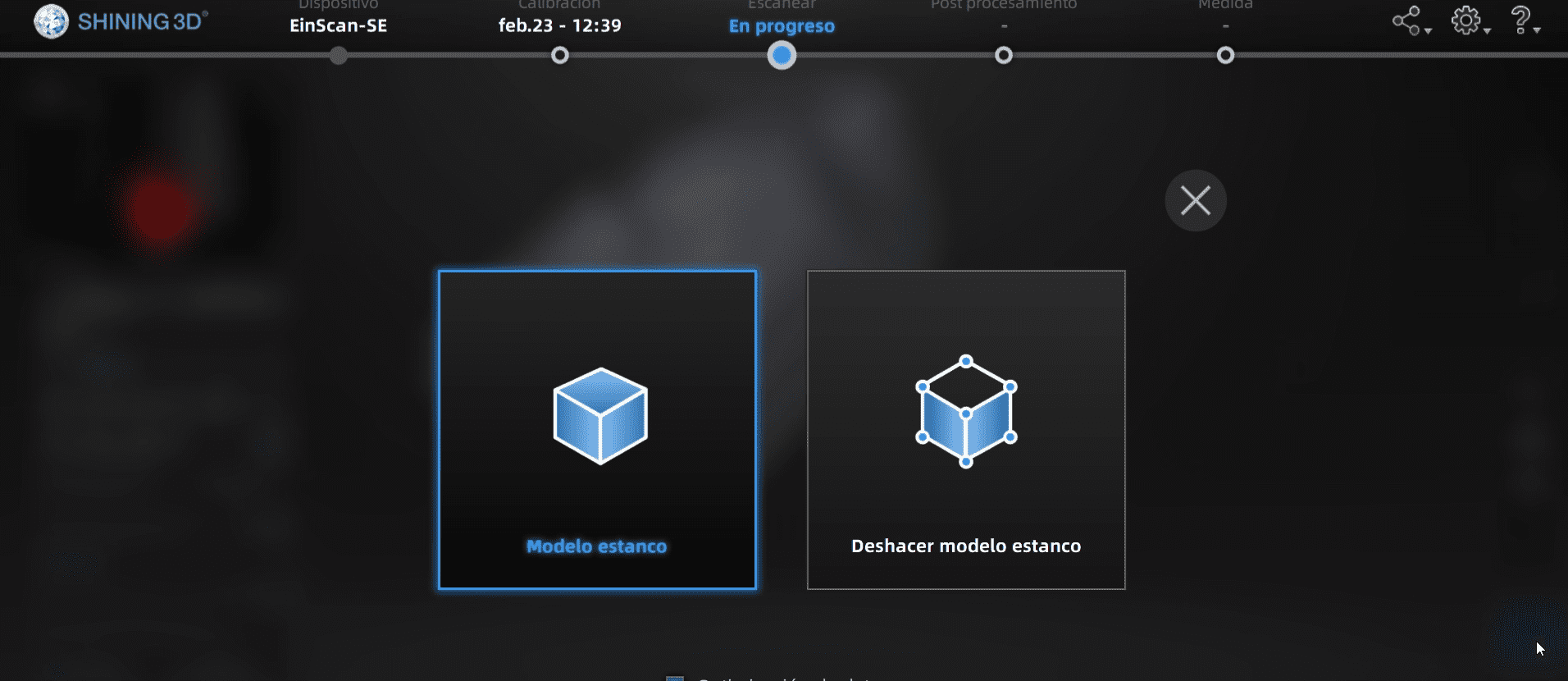
- After completing the scan, the software may provide tools for data processing. This could include merging scans, removing artifacts, or generating 3D meshes.
- Finally, export the resulting 3D model in the desired format (e.g., STL) for further use in design software or 3D printing.
Here is a photo of me scanning:
Results
Extra: print the scan
Documents
- Fusion 360 editable document of the fish.
- STL document of the fish.
- The scanner .stl documment is heavy (120mb :0), that's why I didnt put it.
- Also the fusion 360 document of my fish is also really heavy, that's why I only put the .STL documment.