Computer aided design
Computer-aided design or also known for its abbreviation (CAD) is a way to digitally create 2D drawings and 3D models of any real product you can imagine.
2D software
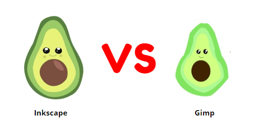
In this practice I tried two different programs: Inkscape and Gimp 2.10.36.

Inkscape

Gimp
Brief comparative table.
| Characteristic | Inkscape | Gimp 2.10.36 |
|---|---|---|
| Software requirements | GHz processor, 512 MB of RAM, and 500 MB of free storage space. | Windows 10 version 0.0 or higher, 4 GB (Minimum), 16 GB (Recommended). |
| Type of Software | Vector Graphics Editor- | Raster Graphics Editor. |
| Aplications | Illustrations, logos, icons, diagrams. | Photo editing, image manipulation. |
| Interface | User-friendly with a focus on simplicity. | Complex, geared towards advanced users. |
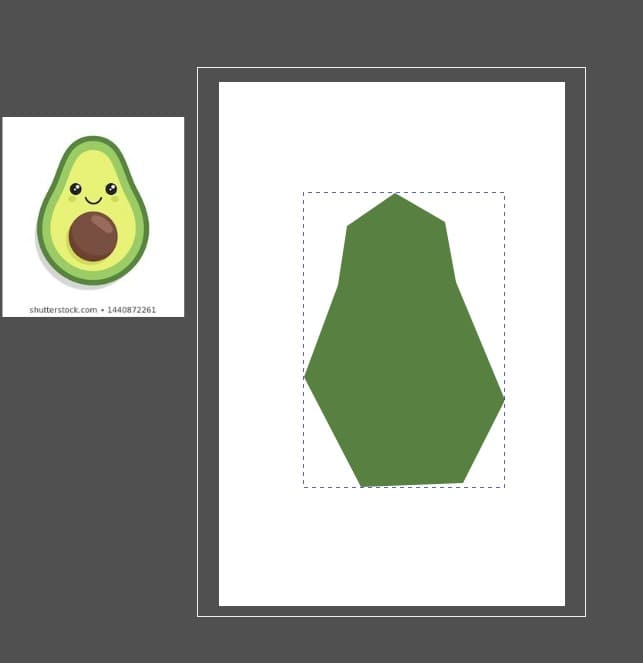
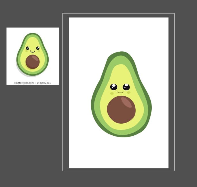
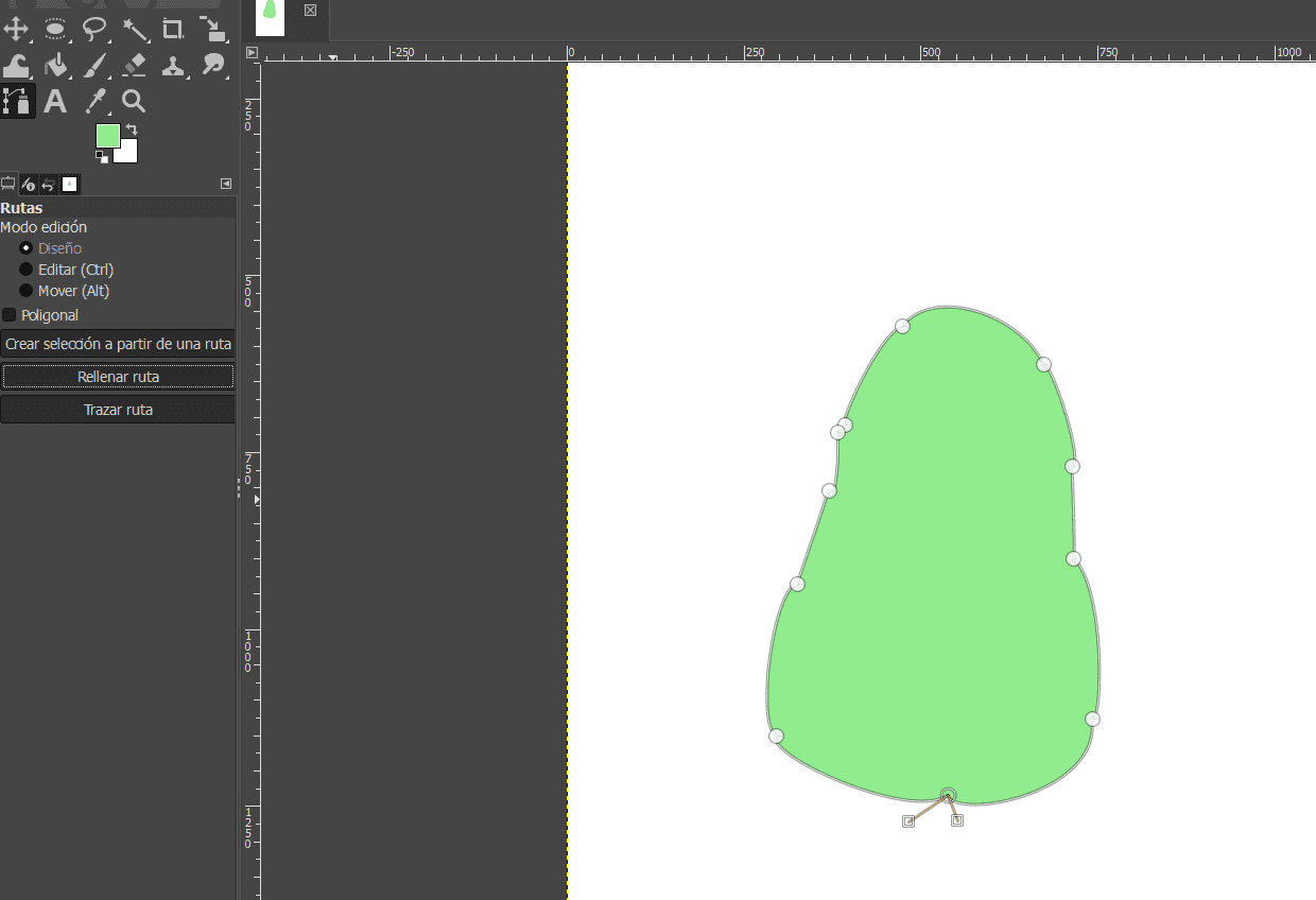
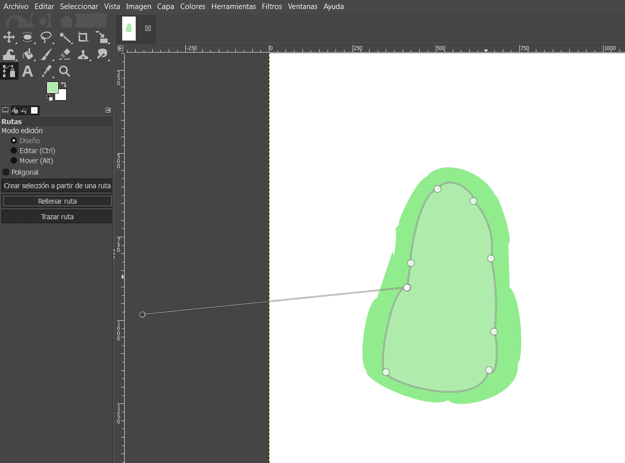
In this case I made the same drawing with both programs and I prefered Inkspace because it was easier to manage. First I will show you both drawings and then the explication in Inkspace.
Inkscape
Opening Inkspace
- Launch the Inkscape application on your computer.
- Once Inkscape is open, locate and click on the "File" menu in the top-left corner of the Inkscape window.
- From the "File" menu, hover over the "New" option to reveal a submenu.
- In the submenu, you can select the type of document you want to create. You can choose from options like "Default," "A4," "Letter," and others..
- If you need to customize the document properties, you can click on "File" > "Document Properties" and make adjustments such as page size, orientation, units, and more.
- After selecting the document type and adjusting properties if necessary, click on the specific document type you want. This action will create a new document with the chosen specifications.
- In this case we are going to do "Part"
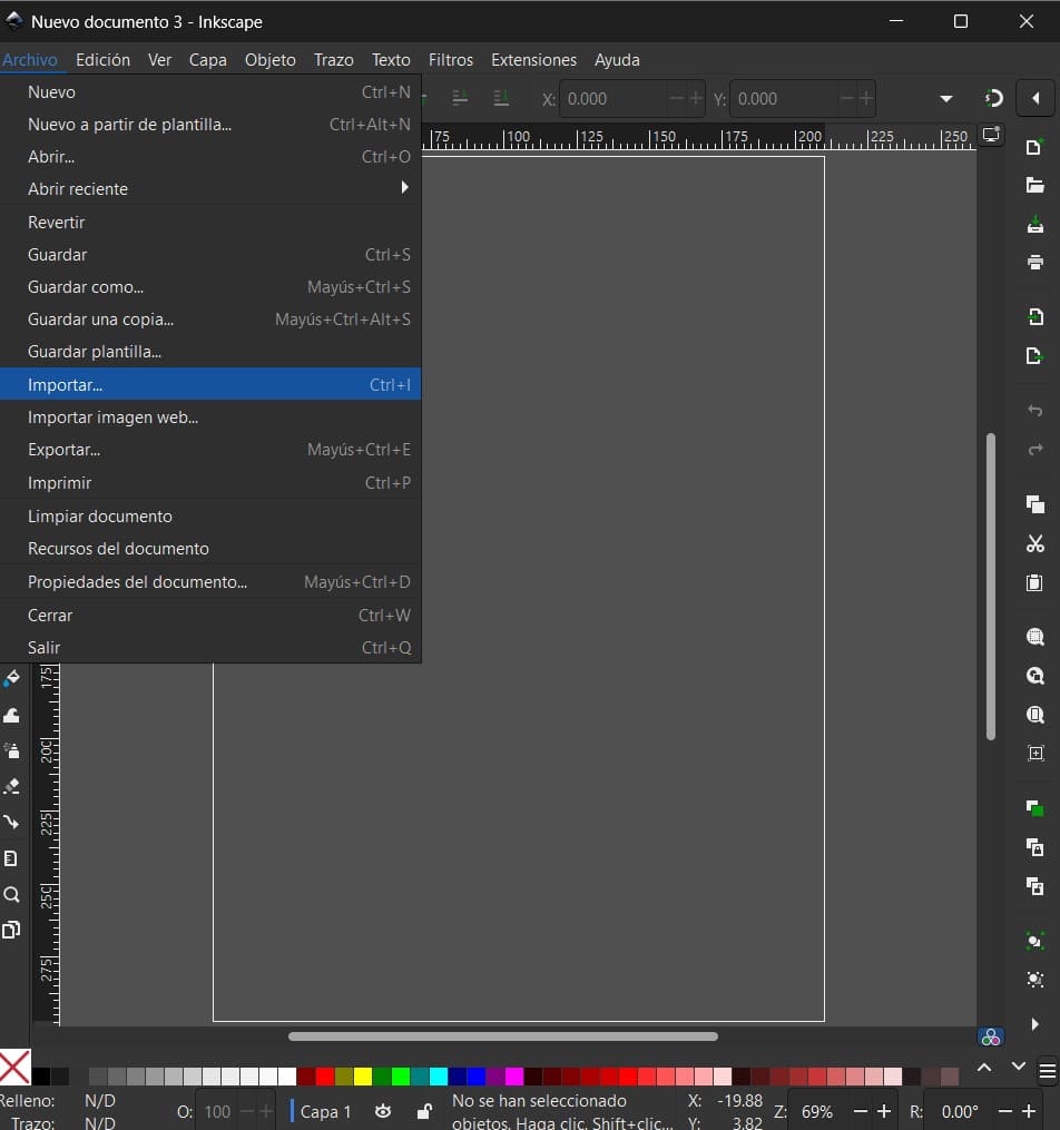
- Once the new document is created, you can start working on your project. Use the various tools provided by Inkscape to draw, edit, and design your vector graphics.

Drawing
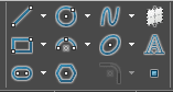
- In the left toolbar, you'll find various drawing tools. The primary drawing tools include the "Rectangle," "Ellipse," "Freehand" (Pencil), "Pen," and more. Click on the tool you want to use.
- Once you've selected a drawing tool, you may see options in the toolbar at the top for that specific tool. Adjust settings such as stroke color, fill color, stroke width, and more as needed.
- Use the selected tool to start drawing on the canvas. For example, if you selected the "Pen" tool, click on the canvas to create anchor points, and Inkscape will connect them to create a path.
- Inkscape allows you to edit and modify your drawings. You can use the "Node" tool to adjust individual nodes on a path, change the shape, and refine your drawing.
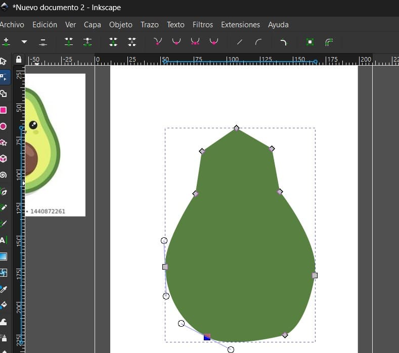
- Inkscape utilizes layers to organize your drawings. You can access the "Layers" dialog (usually on the right side) to manage layers, hide or show elements, and rearrange objects.
- Inkscape offers various tools for different tasks. Experiment with tools like the "Bezier" tool for precise curves, the "Text" tool for adding text, and others.
Saving the document
- Periodically save your work to avoid losing any progress. Use the "File" menu to save your document.
- When you're finished with your drawing, you can use the "File" menu to export your work in various formats or save it in a specific location.
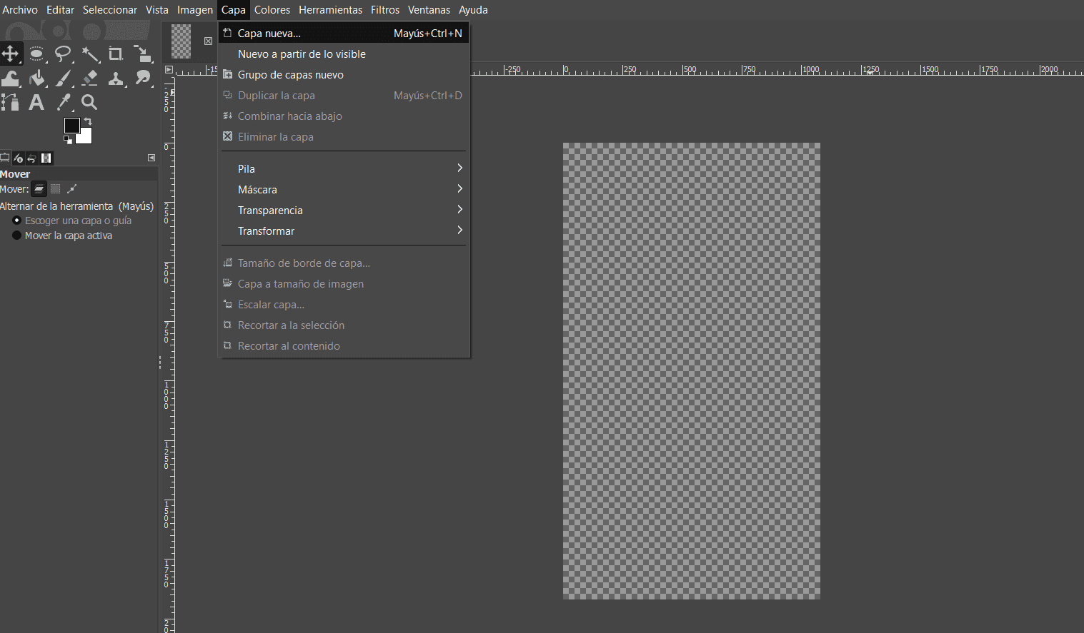
Gimp
- Launch the GIMP application on your computer.
- Once GIMP is open, you can create a new document by going to the menu bar and selecting File > New.
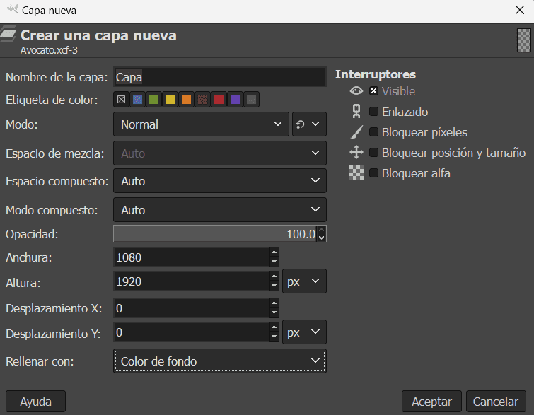
- In the "Create a New Image" dialog box, you can set various properties for your new document: Width and Height: Enter the dimensions of your document in pixels, inches, or other units. Resolution: Set the resolution of your document (usually 300 pixels/inch for print, 72 pixels/inch for web). Advanced Options: Here, you can choose the color space, fill with, and other advanced settings.
- Once you've set the desired properties for your new document, click the "OK" button.
- After clicking "OK," a new window with your specified document properties will appear. This is your canvas, and you can start creating your image.
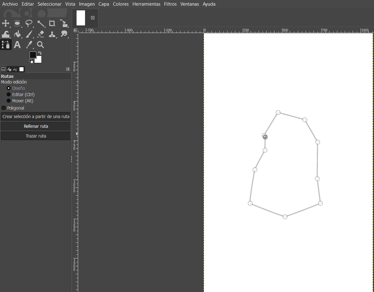
- You can use a tool that is similar to Inkscape, so you put dots and after that you can mold it as you wish.
- You can use the various tools, brushes, and features in GIMP to start designing or editing your image.
- Also you can add text.
- After you've created your document, remember to save it. Go to File > Save As to save your work in GIMP's native XCF format or export it to other common formats like JPEG, PNG, etc.
3D SOFTWARE
In this practice I tried two different programs: SolidWorks and Fusion 360.


SolidWorks

Fusion 360
Brief comparative table.
| Characteristic | SolidWorks | Fusion 360 |
|---|---|---|
| Software requirements | 64-bit; Intel or AMD processor, 16 GB RAM, certified GPU. | 3.0 GHz or greater 64-bit processor with 6 or more cores, 8 GB RAM, dedicated GPU with 4 GB or more. |
| Functionalities | In solid you can create separted parts and create different assemblies. | Everything is created and assembled at the same time. |
| Aplications | It is more for heavy machinery industries. | It is more versatil. |
| Support | I could observe ther are many curses/videos/classes for starters, unfortunately most of them needed to be paid. | There is more free content to learn how to use it. |
| Way of using it | As I was familiar to Catia, learning SolidWorks was easier. | As I was not familiar to modeling the object literally, it was much harder. |
As you can see in the comparative table, I prefered using SolidWorks because I am more used to that program and in my opinion I think it has many tools for simulation and assemblies compared to Fusion.
Creating a possible project
Opening Solidworks
- Open the Start menu or the application launcher on your computer.
- Look for the SolidWorks icon or type "SolidWorks" in the search bar to find the application.
- Double-click on the SolidWorks icon to open the application.
- Once SolidWorks is open, you'll typically see a welcome screen or a menu bar. Look for an option to start a new document or project.
- Click on "File" in the menu bar and select "New" or a similar option.
- SolidWorks often provides templates for different types of projects, such as parts, assemblies, or drawings.
- In this case we are going to do "Part"
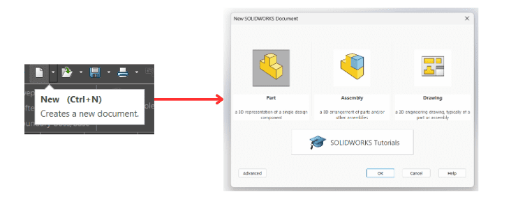
- Before generating the document, it's important to set document properties such as units (millimeters, inches, etc.), dimension standards, and other relevant settings.
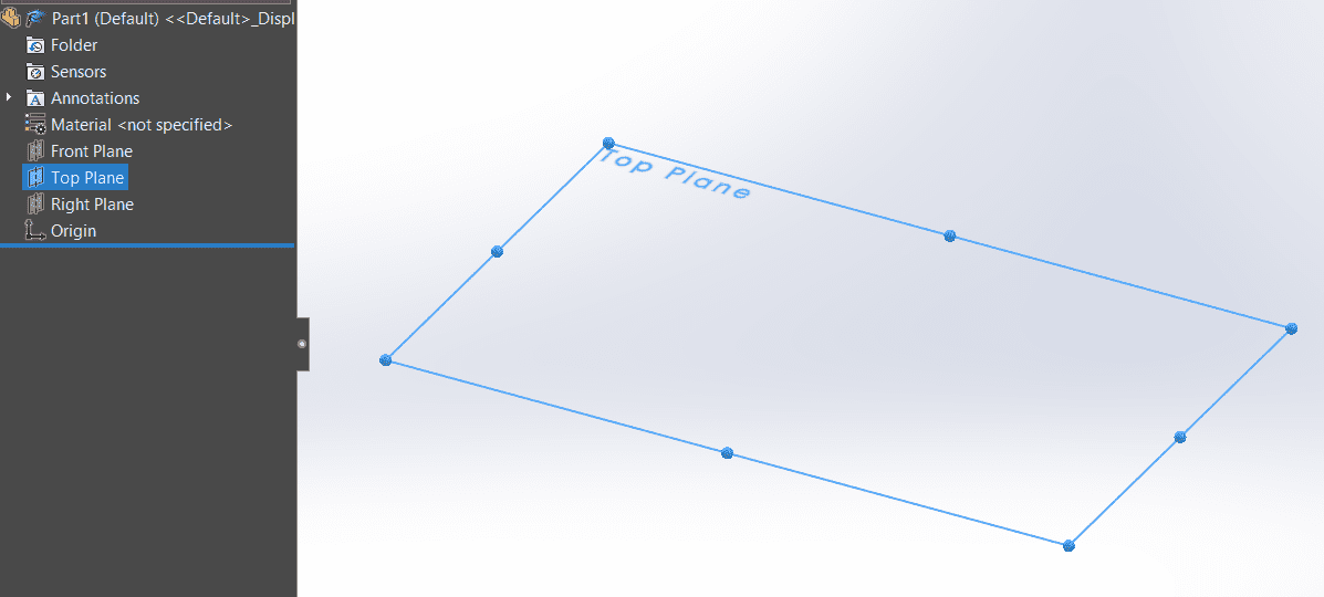
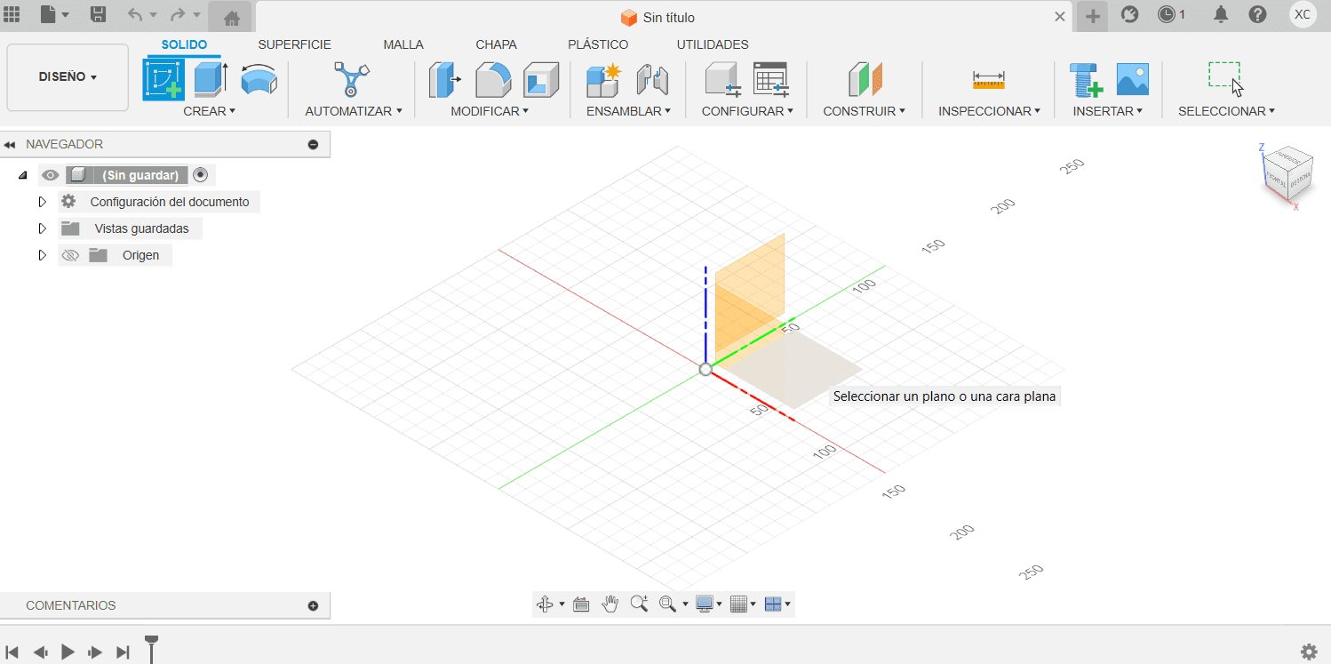
Choosing a plane
- On the left side of the SolidWorks window, you will find the FeatureManager Design Tree. This tree displays the features and components of your part or assembly.
- In the FeatureManager Design Tree, find the "Plane" icon. It usually looks like a triangle representing a plane. Click on this icon to activate the Plane feature.
- After activating the Plane feature, SolidWorks will prompt you to choose a reference plane. Reference planes are predefined planes in your model, such as the front, top, or right planes.
- Click on the desired reference plane in the graphics area. Commonly used planes are Front, Top, and Right.
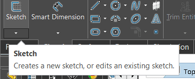
Sketch tools
- The Line tool allows you to draw straight lines by clicking to define each endpoint. Pressing "Esc" or right-clicking ends the line.
- Centerlines are used for symmetrical sketches.
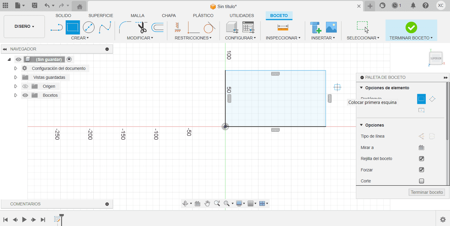
- The Rectangle tool creates rectangular sketches. You can choose to define a rectangle by two corners or by center and dimensions.
- The Circle tool creates circular sketches.
- Arcs can be drawn using the Arc tool, allowing you to create arcs by specifying the start point, endpoint, and radius.
- The Polygon tool lets you draw regular polygons with a specified number of sides and center.
- Splines are smooth curves that can be created using the Spline tool.
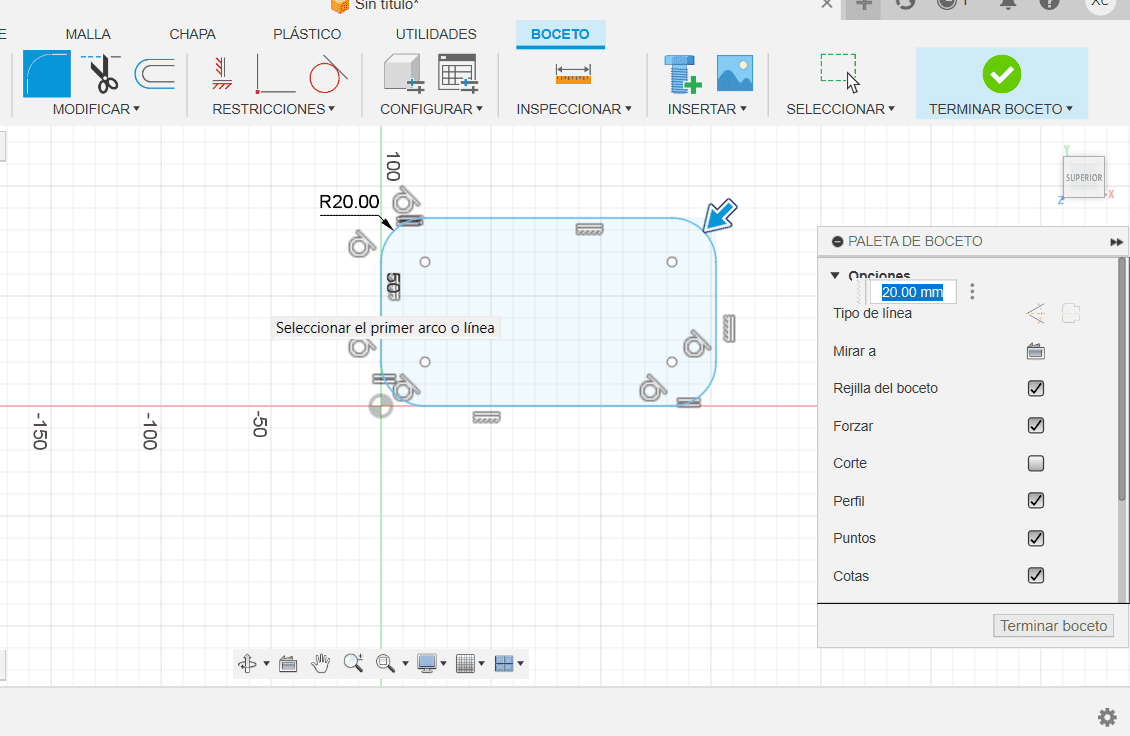
- Fillet and Chamfer tools allow you to round or bevel the corners of your sketches, respectively.
- Fillet and Chamfer tools allow you to round or bevel the corners of your sketches, respectively.
- The Offset Entities tool creates a copy of selected sketch entities at a specified distance.
SolidWorks
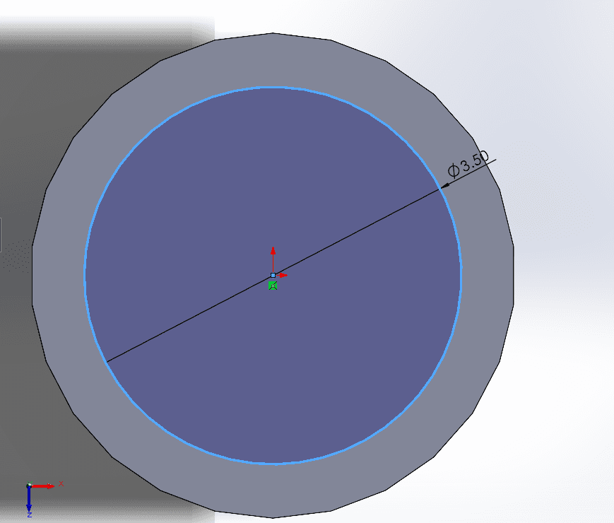
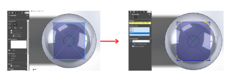
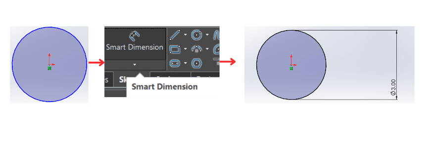
- First using the circle tool, we sketch the respetive figure.
- With the Smart Dimension tool activated, click on the sketch entity (line, circle, arc, etc.) that you want to dimension.It is important to mention that fisr will lokk blue and after using smart dimension, it will be color black.
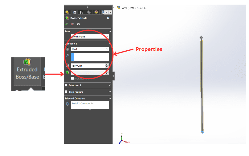
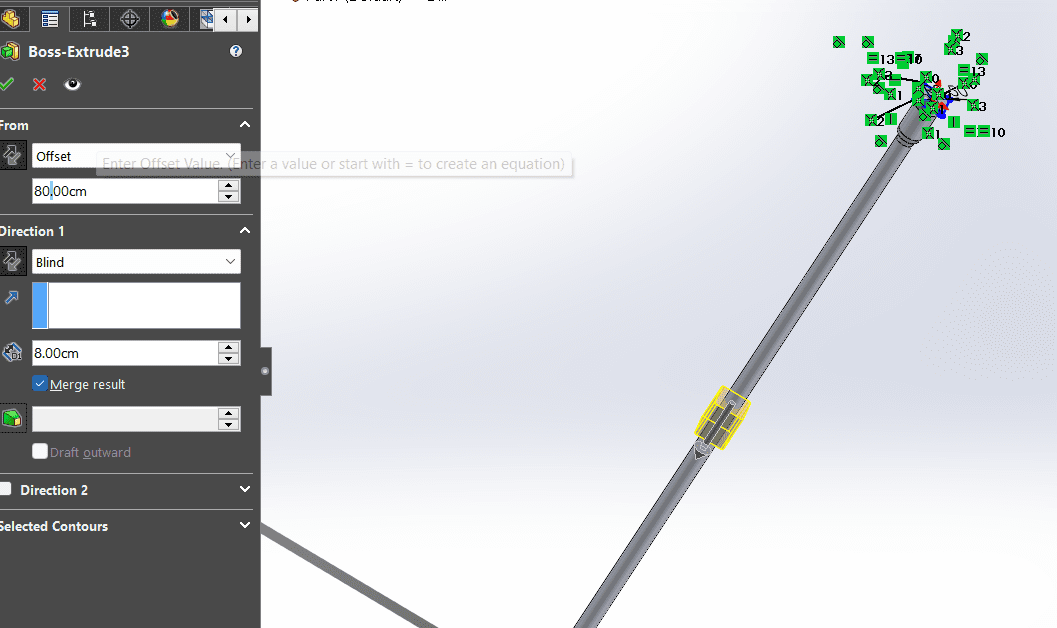
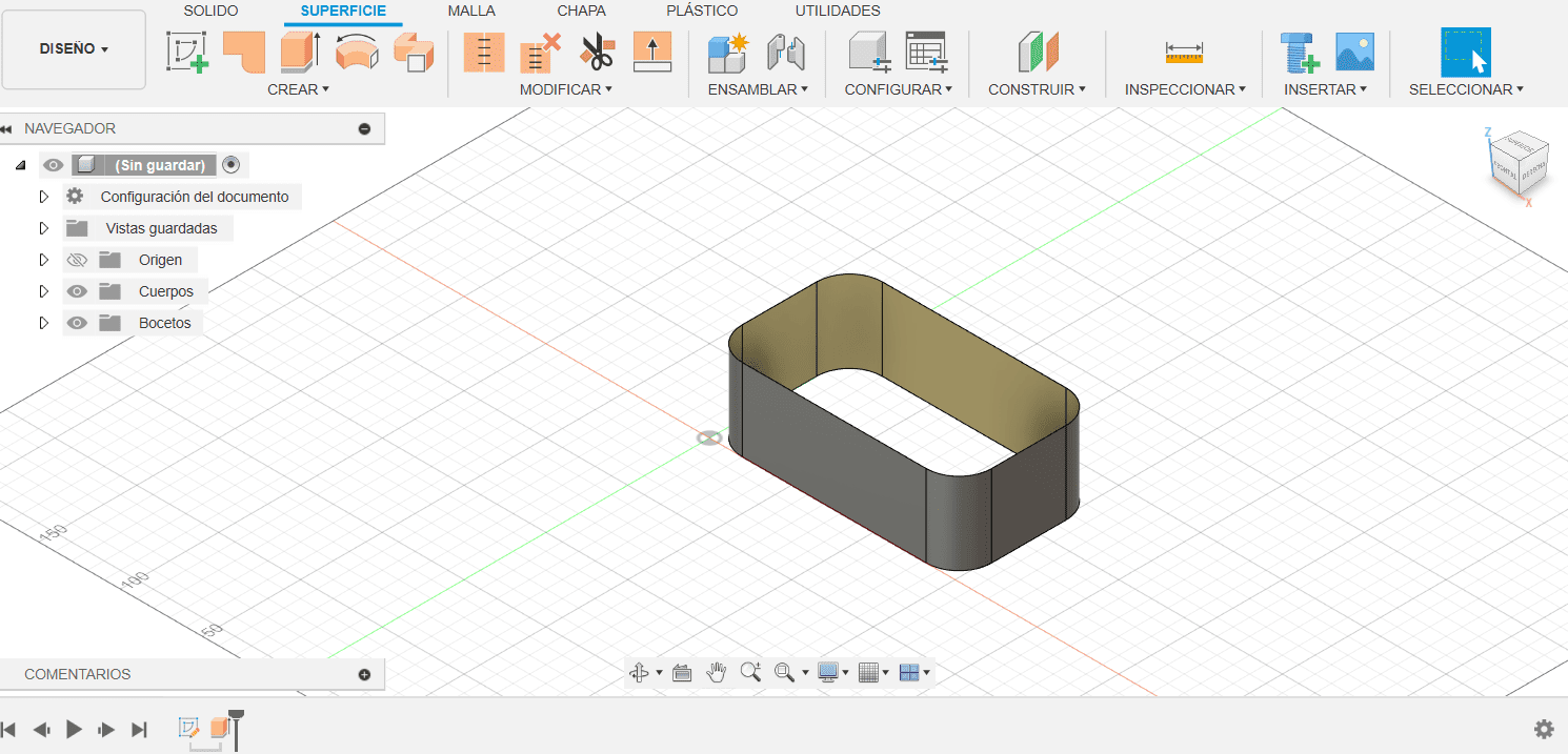
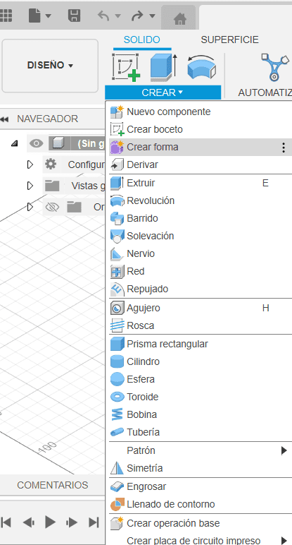
- After creating a sketch, the Extrude tool allows users to give the sketch depth, essentially adding volume to the design. When activated, the tool prompts the user to select a sketch and then define the extrusion parameters, such as the extrusion distance or up to next feature.
- It is necessary to create another sketch above the one we extruded.
-
The Cut Extrude tool in SolidWorks is a feature that allows users to remove material from a 3D model based on a specified sketch. By selecting a sketch profile and defining the depth or end condition, the Cut Extrude operation essentially subtracts the sketched shape from the existing geometry, creating voids or cavities within the part. This tool is widely used for creating holes, pockets, or intricate patterns in a model, and it provides flexibility in terms of direction and extent.
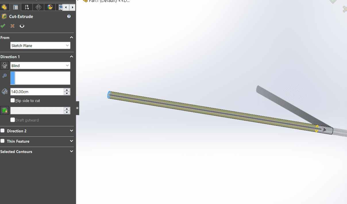
- Over the figure made, I draw a new sketch to make the part, were the vibrator was going to be.
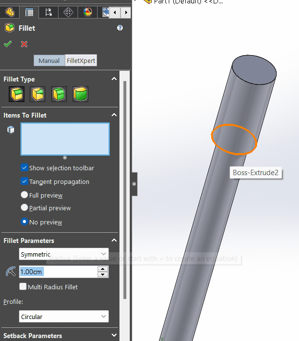
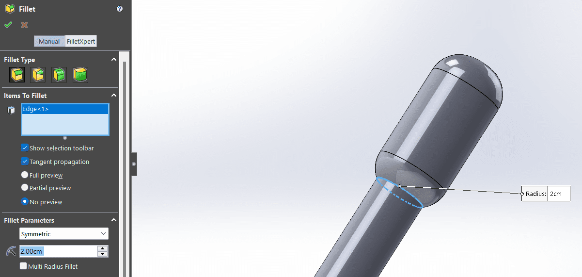
- In SolidWorks, the Fillet tool is a feature used to round or create a curved transition between two selected edges or faces in a 3D model. The Fillet tool is particularly useful for improving the aesthetics of a design, eliminating sharp corners, and enhancing the manufacturability of parts. When activated, the Fillet tool allows users to specify a radius for the fillet, and then select the edges or faces they want to fillet.
- Above everthing I created a new sketch above everything I had done, were also the tool "Fillet" rounded some parts in the sketch in 2D.
- It is important to mention that when doing "Extrude" there is a section were you put "offset" and you can give volume to the form you want to at any level in specific.
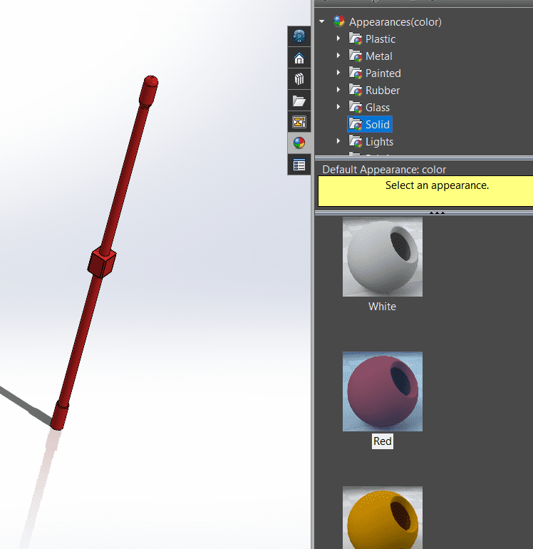
- On the left side of the SolidWorks window, you'll find the FeatureManager Design Tree. This tree displays the features and components of your part.In the FeatureManager Design Tree, right-click on the "Material" icon. If your part doesn't have a material assigned yet, this icon might appear as a gray sphere.From the context menu that appears after right-clicking, select "Edit Material."After selecting the material, click "Apply" to assign it to the part. You may also click "Close" to exit the Material dialog without applying the material.
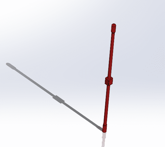
- Here is the final product:
- Make sure to save everything correctly!!
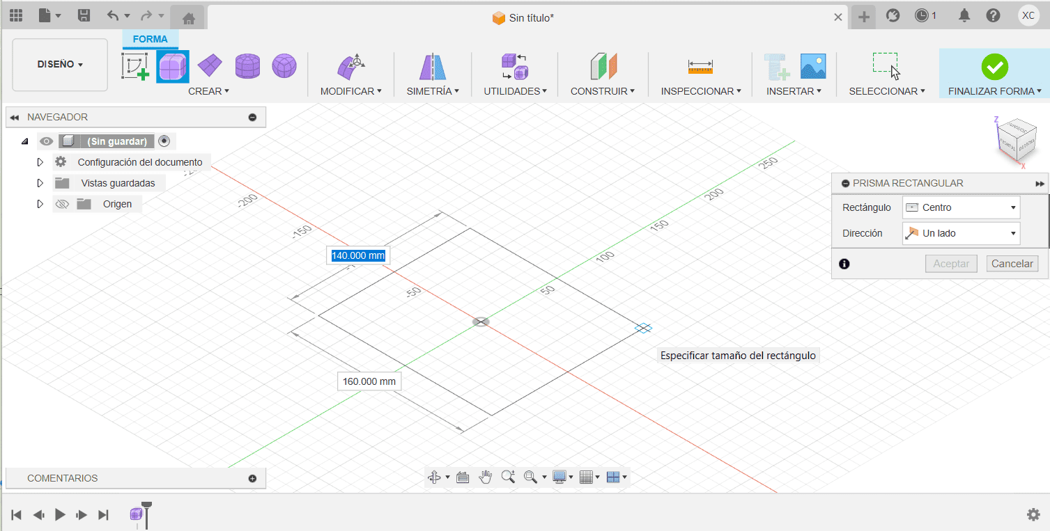
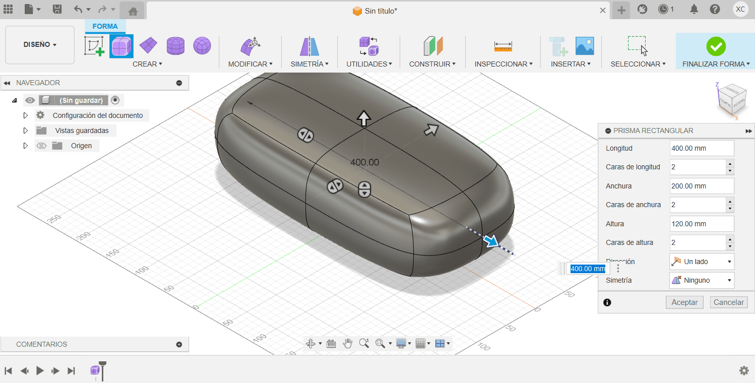
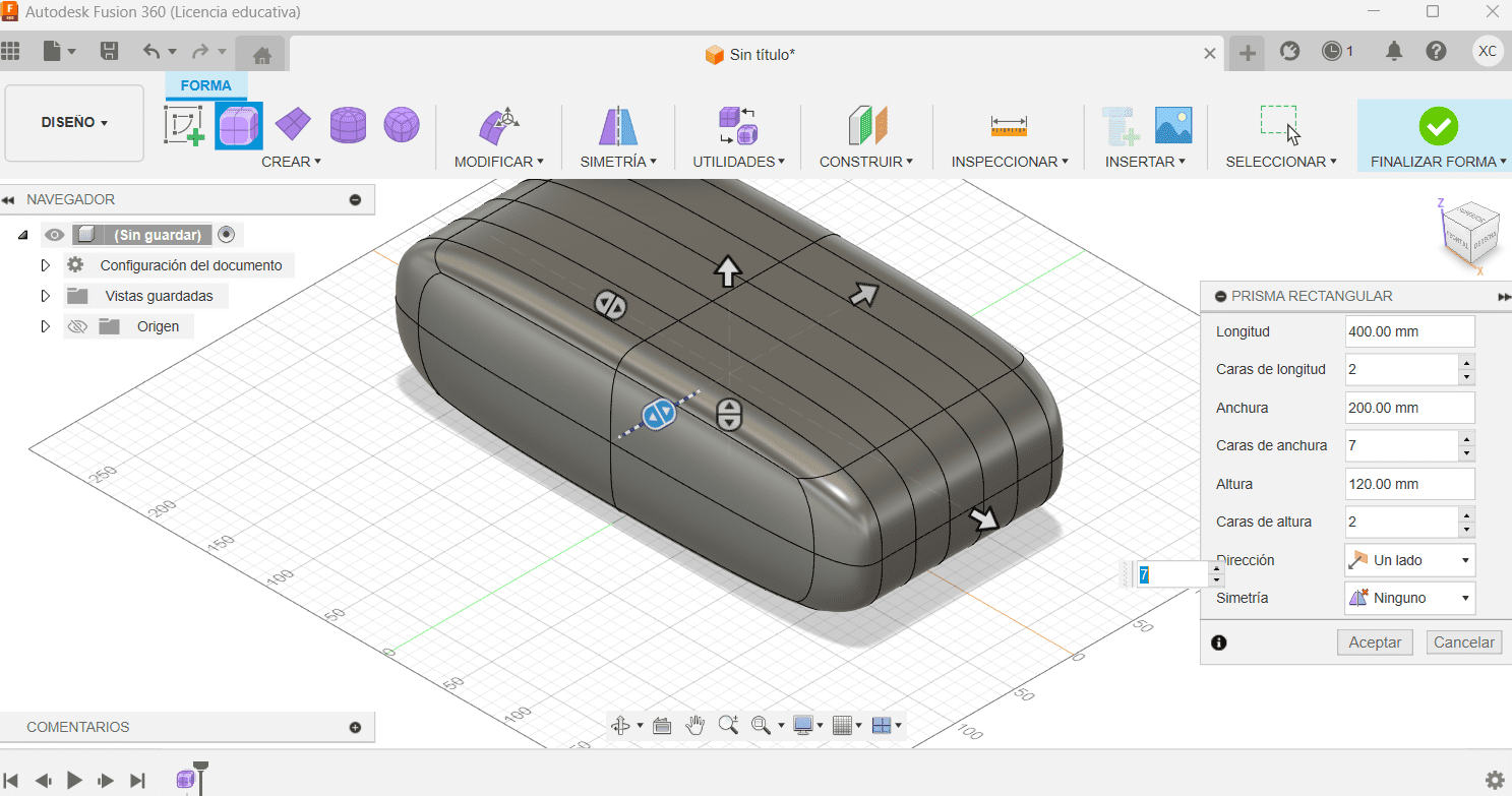
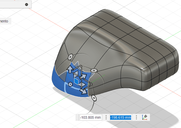
For this case we are doing the possible structure for the cane of my final project.
Fusion
- Launch Fusion 360 on your computer.
- In the workspace, click on the "New Design" button to start a new design project.
- Fusion 360 uses a component-based design approach. Start by creating components that represent the different parts of your design. Use the "Create" menu to add new components.
- Create 2D sketches on the different planes (XY, XZ, YZ) within your components. These sketches will serve as the foundation for your 3D geometry.
- Extrude your 2D sketches to create 3D objects. Use the "Extrude" command to give height to your sketches. You can also perform other operations like revolve, sweep, and loft to create more complex shapes.
- Before creating a mold, consider the design and geometry of your part. Identify the features that will require a mold, such as bosses, holes, or complex surfaces.
- Use the "Split Body" or "Split Face" command to split your design along the parting line. This will result in two bodies representing the core and cavity.
- Export your mold design in a format suitable for manufacturing, such as STL, and share it with your manufacturing team or service provider.
- After you've created your document, remember to save it. Go to File > Save As to save your work in GIMP's native XCF format or export it to other common formats like JPEG, PNG, etc.

- Cane
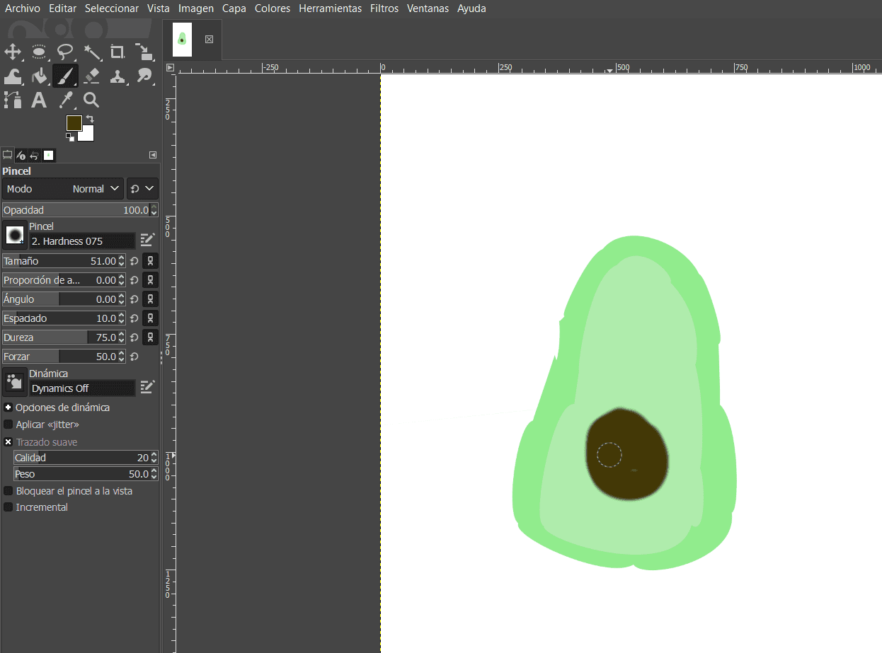
- Avocato in Inkscape
- Avocato in Gimp
Documents