10. Machine design
On this week we worked on THE CREATION OF THE CNC (difficult week)
The group assignment
Here is the group assignment where you can find what we did as a team, the final result and the contribution of others.
My contribution: bed of the machine, assembly, 3D printing, ...
The machine has tree axis x, y, and z. The bed is going to be z axis which is a very important one.
The first step was to know the measures of the structure, this to know where the acme screw spindle, and the 8 mm chrome rod guide were going to be.

Now lets go to the design.
The first step was to measure the Sc8uu linear bearings this in order to know where the screws are going to be. The screws that we used were M4 screws.
- M4 screw: 3.7 mm
- M4 screw head: 6.8 mm
The dimensions of the bed are:
- Width: 16 cm
- Height: 27 cm
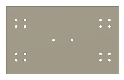
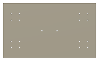
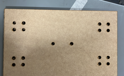
2 of each part are needed in order to give more thickness, this to make the screw does not protrude. Those were cutted on the laser machine on 3mm MDF.

Then we need to create the 3D support for moving the bed on the axis. This piece is important and was created measuring the acme screw spindle.


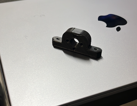
Time to put all together on the base, this by screwing.
What were are going to screw is the 3D piece and the Sc8uu chrome rod guide, these ones are going to have the linear bearing.


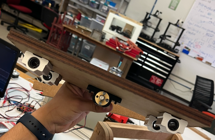
Finally we insert the bed on the structure and we have this:
