3. Computer-Controlled Cutting
This week I worked on Computer Controlled cutting. The first step was to start knowing how the machines work.
The group homework
The group assignment link is here. That's what as a group we worked on this week. We saw topics as KERF, the laser cut, how it works, and more...
Knowing the machines
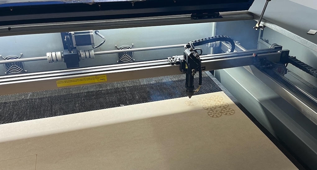
I started this week by giving myself time to know the laser cutting machine. On my local fab we have a CamFive CFL-CMA1390T laser machine which is kind of easy to use.
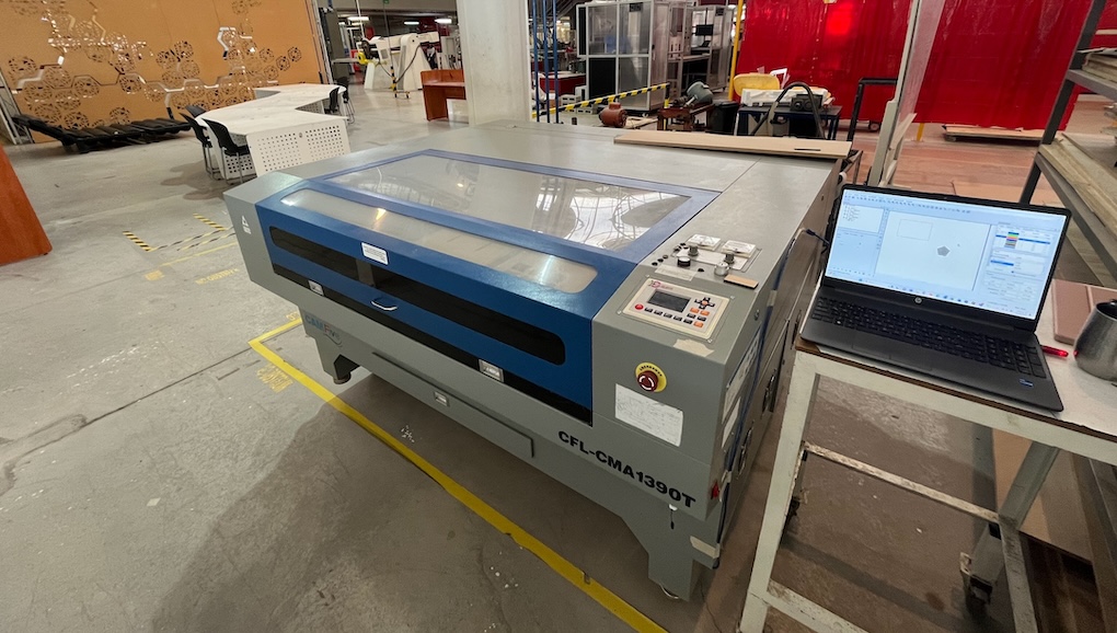
This machine has the next features:
- Work area: 1.30 x .90 meters
- Cutting speed: 0-36000 (min/mm) It can be more or less depending on the material
- Engraving speed: 0-64000 (min/mm) It may be more or less depending on the material
- Engraving speed: 0-64000 (min/mm) It may be more or less depending on the material
- Cutting thickness: 0-25 mm May be higher or lower depending on the material
- Resolution: Up to 4000 DPI (normal between 600 DPI and 2000 DPI)
- Minimum configuration: Characters 2 x 2 mm and letters 1×1 mm
- Location precision: 0.01mm
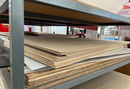
This machine works with a huge kind of materials, such as:
- Paper
- Cardboard
- Foaming
- Felt
- Cotton
- Wood
- MDF
In this case I'll be using MDF (pressed cardboard) which is useful to create a press fit kit that is going to be durable.
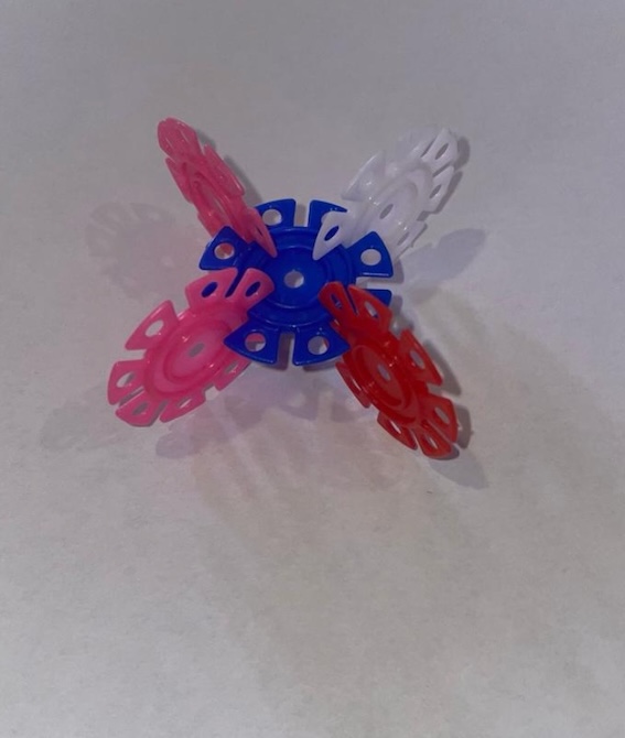
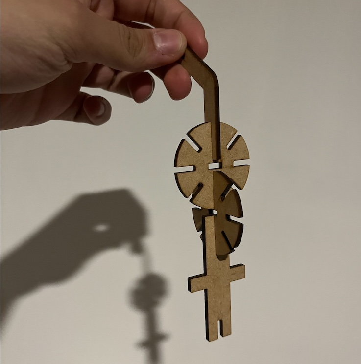
My first idea was based on a toy that I had on my childhood, the toy was a multiple pieces of plastic type coins that had multiple joints.
KERF
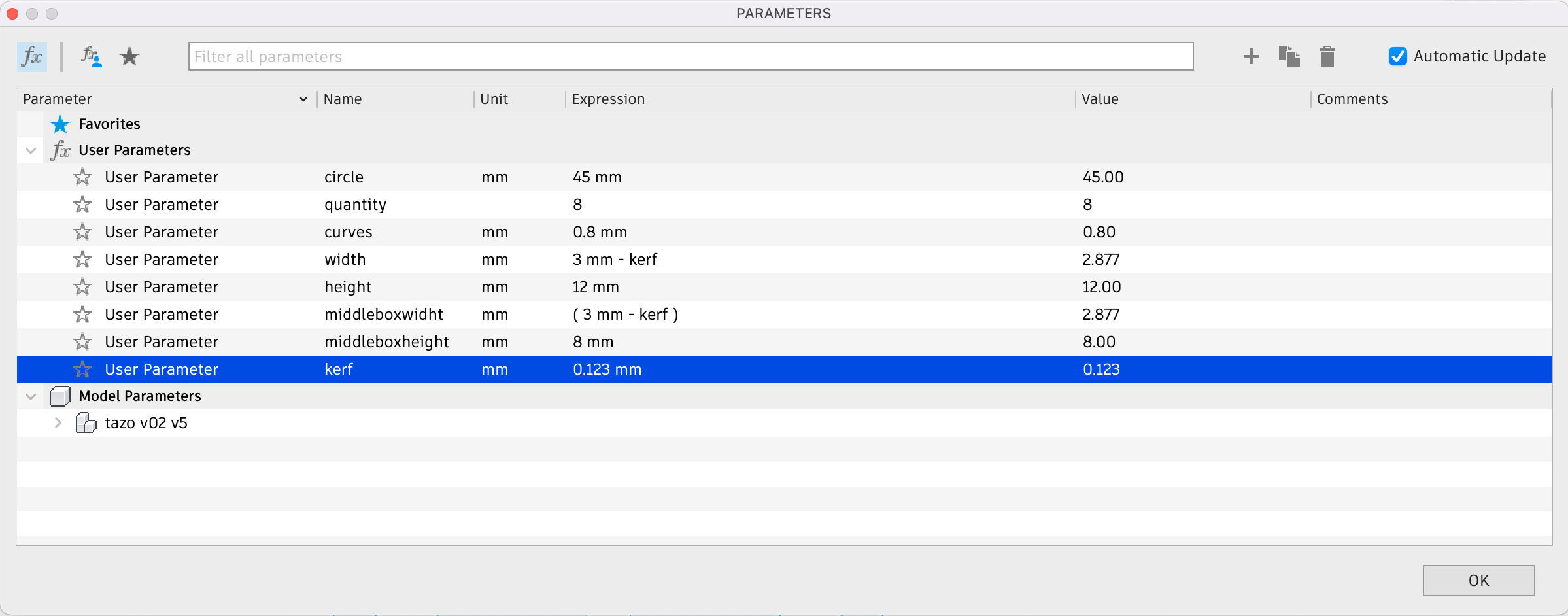
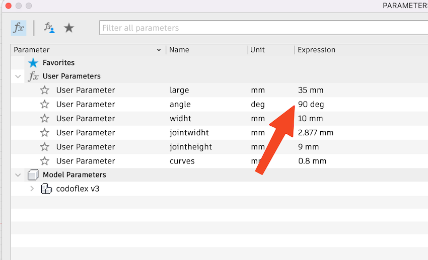
KERF was considered in all the joints, in this case the kerf according to the group homework, then I made the maths and because my MDF piece was 3 milimiters thick the math was 3 - 0.123 and I considered it in all the pieces. It can be seen on every parameters windows that is shown below.
. . .
Start drawing
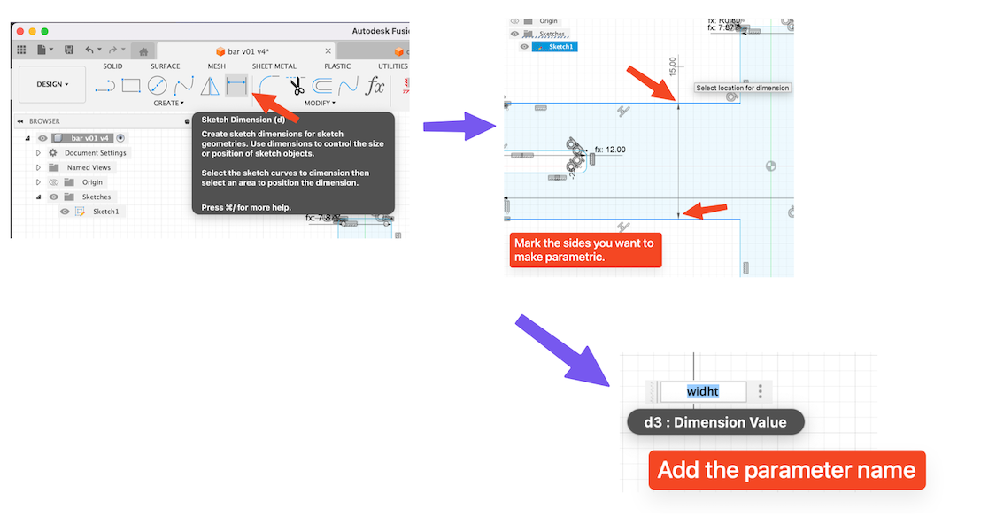
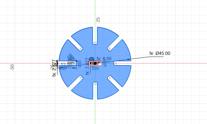
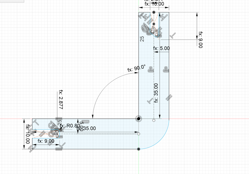
Starting drawing on Fusion 360 was kind of easy but I started drawing the circle and the joints of it. Almost everything is parametric, so almost all measures are parameters.
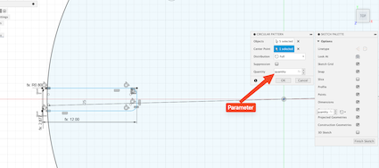
The parameters were added following the next image, this were on all the designs:
All the parameters of the circle:
For this, I used KERF as a parameter, so it only makes the math applying it as - kerf
Then we have the piece on Fusion 360. This is the final result after using figures as rectangles and parameters on everything.
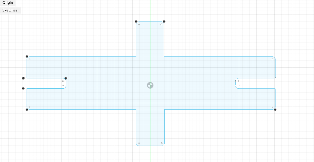
The second figure I made was a rectangle which had joints compatibles with the circle and also one compatible with the middle of the circle.
Finally I made an elbow-like piece with a 125 degree inclination, this is too compatible with the other two figures/pieces.
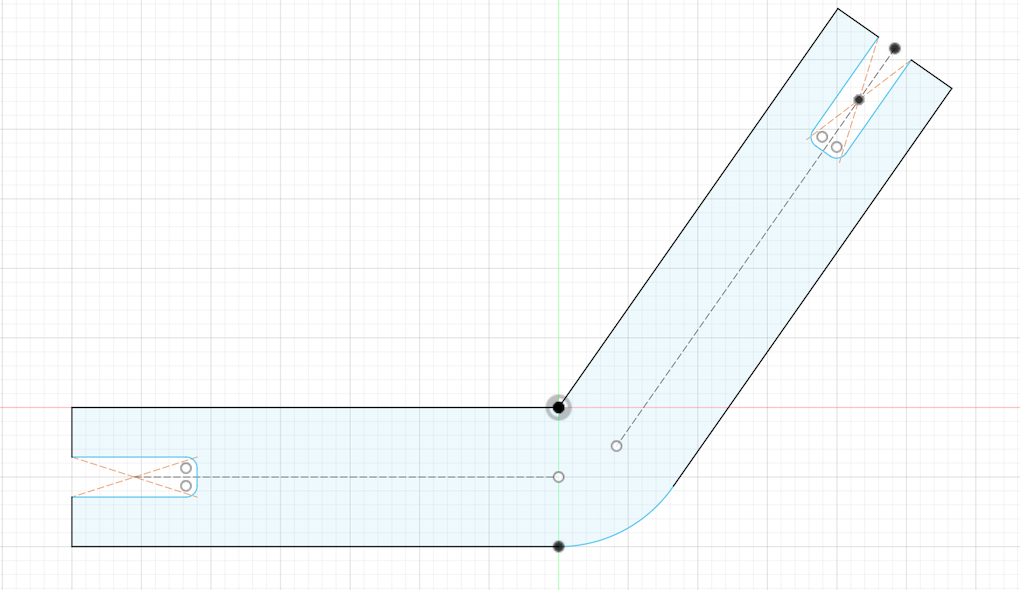
Example of moving parameters
In this case the elbow can change it angle with parameters. On this example we will use an 90 degrees angle.
The angle changed:
. . .
Cutting on laser
After learning how to use the laser, we needed to export the files on the .dxf format to pass it to the Smart Carve software which needed a key to use.
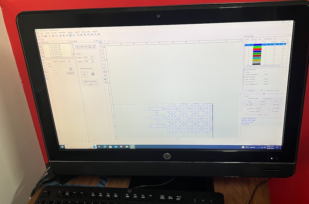
The cut parameters that I used for this clean cut were:
- Max. power: 60
- Min. power: 50
- Speed: 25
The characterization of the laser, and more details about the Speed/power can be found on the group assignment.
The next step was to cut it on the laser, for this i needed to mark the 0 piece (the point of start), then to Go scale to check if the dimensions are the correct and finally cutting.
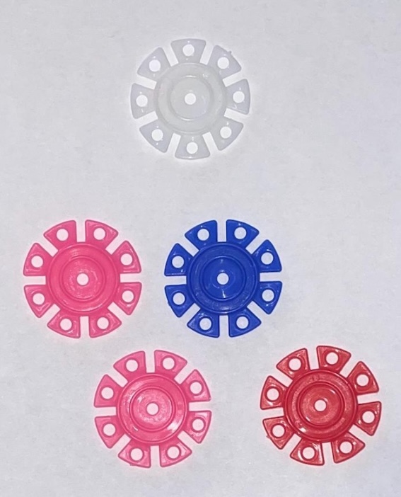
This were the pieces
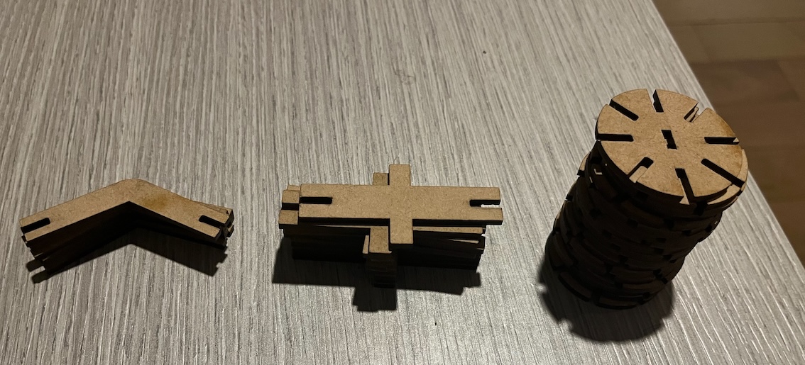
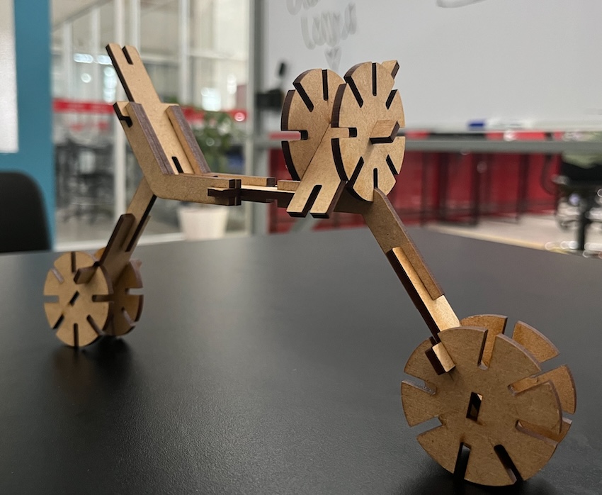
After cutting all the pieces on the laser, I checked if the kerf was the correct one checking if the joints of the pieces were under pressure
Then I started playing with them and got a bicycle:
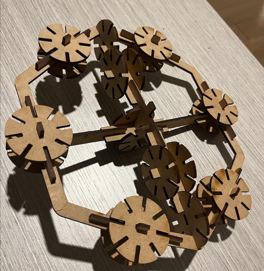
Finally I made a weird thing that only the imagination can name. In this I use almost all the pieces.
Vinyl cutting
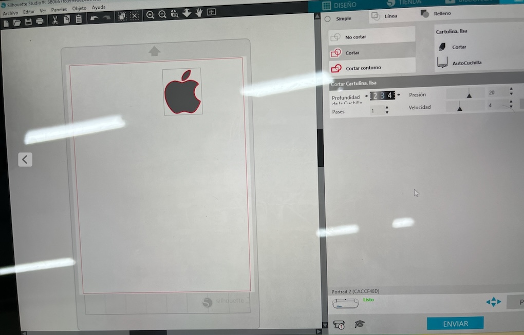
This task was little easier than the laser cutting. In this case I first installed the Sillhouette Studio app in which I only needed to paste the image I wanted to cut.
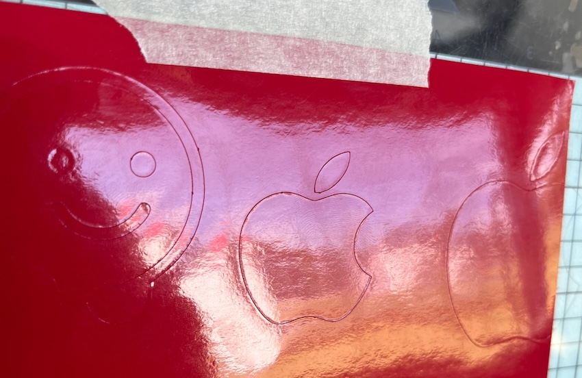
The Sillhouette Studio App works by detecting by itself the photo and marking with a red line the parts that are going to be cutted, then after checking the parameters which are:
- Blade depth: 3
- Pressure: 20
- Velocity: 4
- Pases: 1
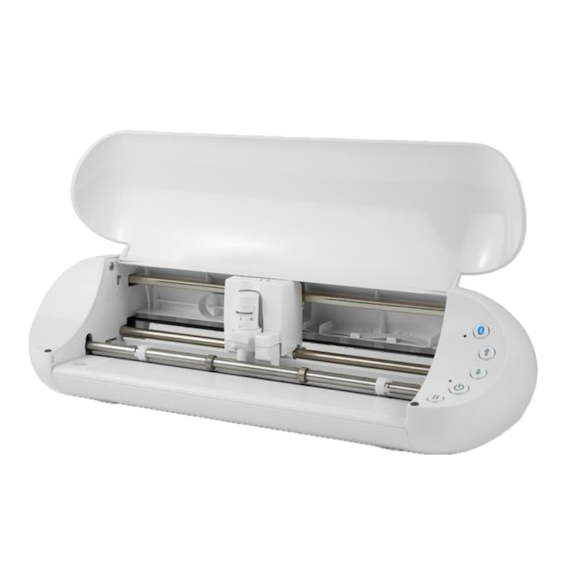
About the cutter is important to know that is a Silhouette portrait studio 3. Which is portable and easy to use. It has bluetooth connectivity and has a powerful software capable of import almost every type of file. It also has a 2mm Clearance which means the machine can cut thicker materials. All of its features are here:
- 8-inch cutting width
- Cut up to 10 feet in length.
- Matless cutting capabilities.
- Automatic tool detection
- Wireless cutting with Bluetooth® connectivity
- Print & Cut registration capability
- Cutting Area: 8 in. x 12 in.
- Maximum Cutting Force: 210 gf.
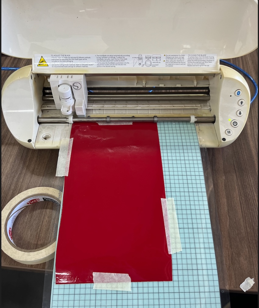
Then I cutted the vynil and charged the cutter, for this I needed to paste with tape the vinyl and then charge the cutter by pressing the input arrow.
The result after cutting:
Using the transfer paper
Pasting it on a door here at the local Fab.