This week, we were assigned a team to design, build, assemble, and program a CNC.
This task was a challenge for all of us since we didn't know each other before.
We had to learn to work as a team with colleagues who weren't even from our degree programs.
The goal of building this CNC was to employ the skills acquired in previous weeks and apply them to a team project.
Our team chose to make a CNC that draws in sand as a decorative piece initially. As the project progressed,
we came up with ideas to potentially create molds with the sand and produce pieces using some other technique in the future.
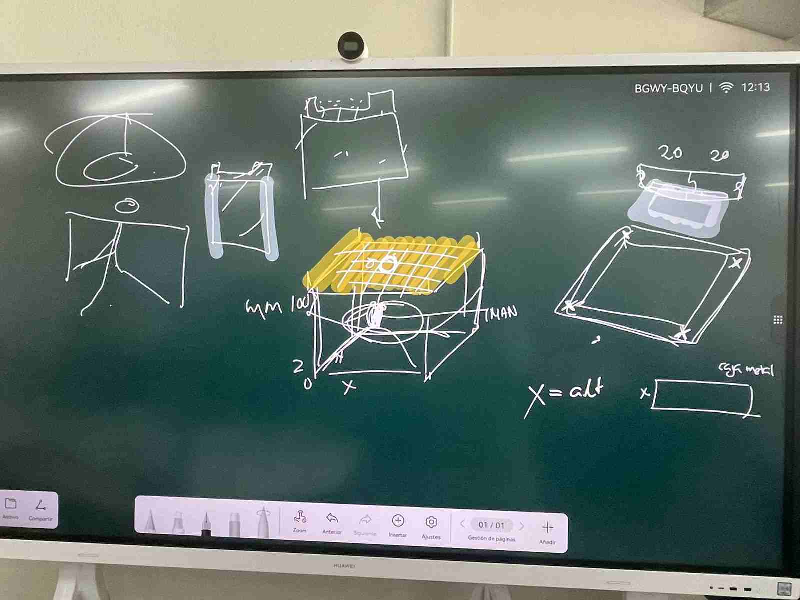
During our first team meeting's brainstorming session, we discussed creating a CNC that draws in sand. The team unanimously
voted in favor of the idea. We then created the initial project sketch, detailing the dimensions, materials, and structure.
The idea was simple in our minds; there would be 2 axes, X and Y. These two axes would perform the drawing in the sand using a
magnet at the tip of the tool, dragging a stainless steel ball, creating the drawing in the sand. Initially, the structure was
intended to be built with 20x20 aluminum profiles, but we encountered the economic limitations of the team and the university
so we decided to make the structure out of 15 mm MDF. The materials considered were smooth rods, plain bearings, and PLA for
3D printing, but we would later discover that we needed more things.
Machinedesign
To create our machine we decided to use a cartesian mechanism where the system would be only used in a planar dimension (XY) and
would have a two step motor for the Y axis and a Single motor for the X axis. To create the design we research for different
commercially available machines that already use this style of kinematics like the UltiMaker 3D printer where the printing head
moves along the XY axis.
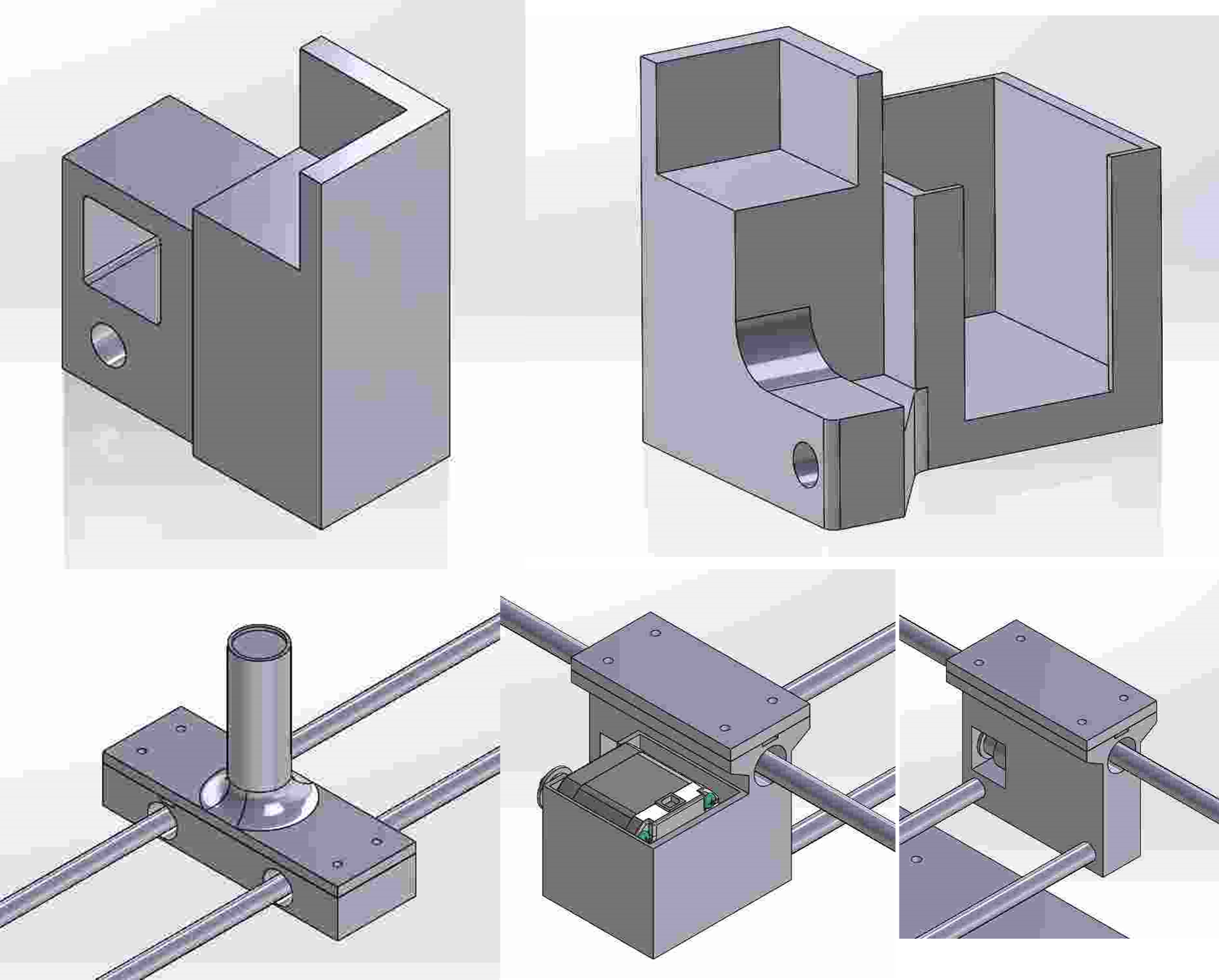
To create our system we would three pieces that will carry the stepper motors, two of them set on two corners that will drive
the Y axis (so this pieces will need to be parallel and mirrored one from another) and another piece that will be placed on
the steel-rod and move along the Y axis but control the X axis.
The following pieces were designed:
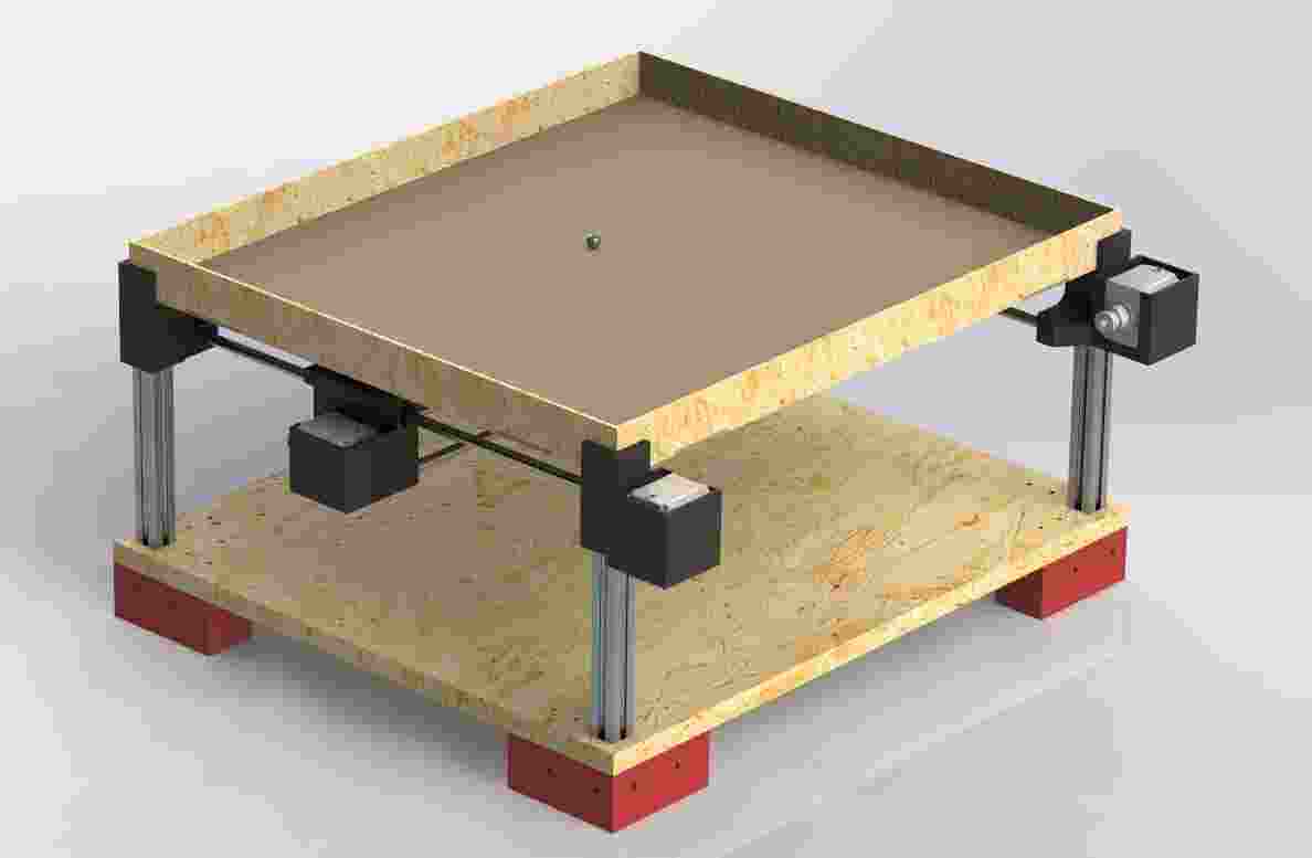
Render
G-code
I was assigned the G-code.
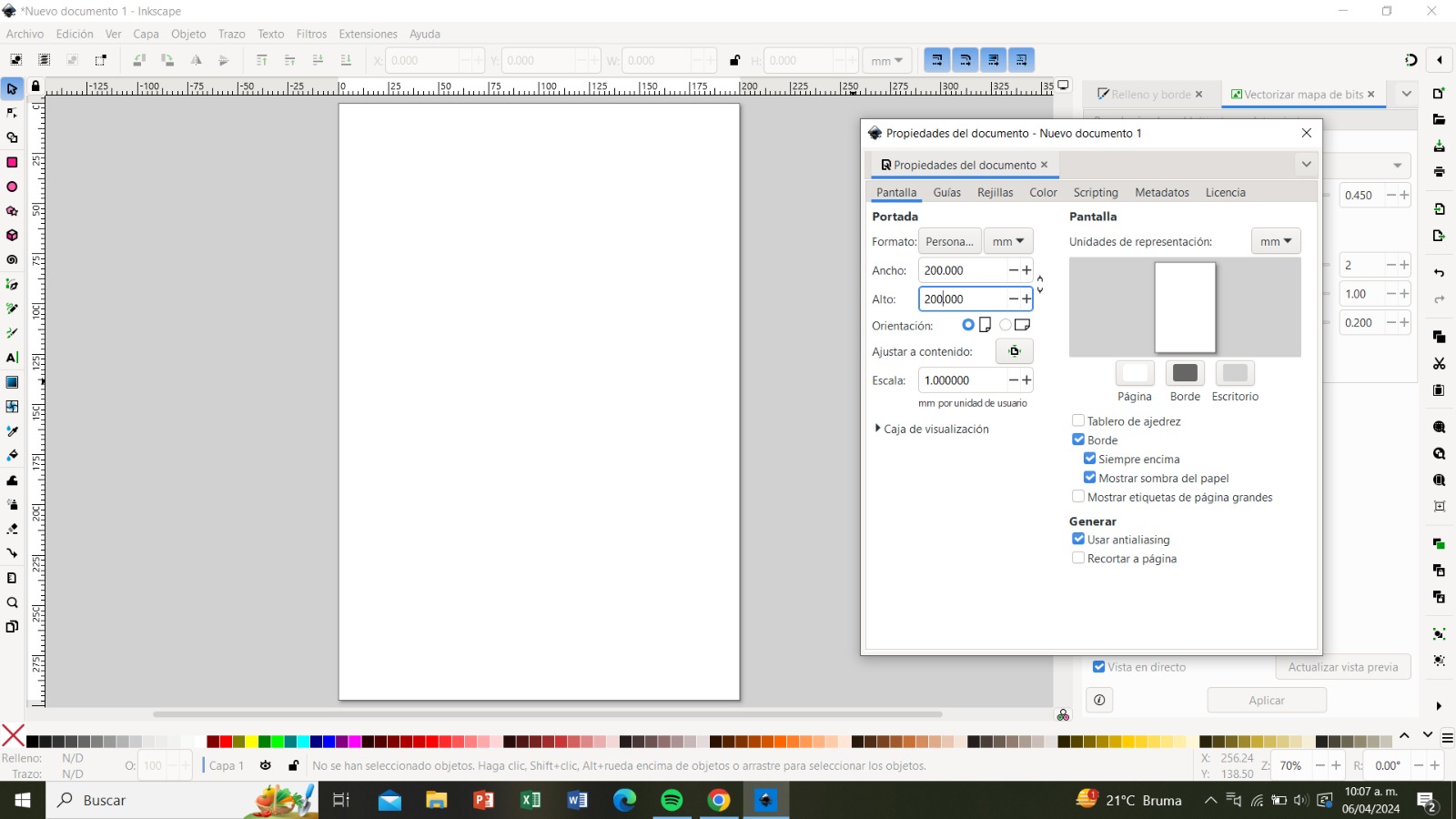
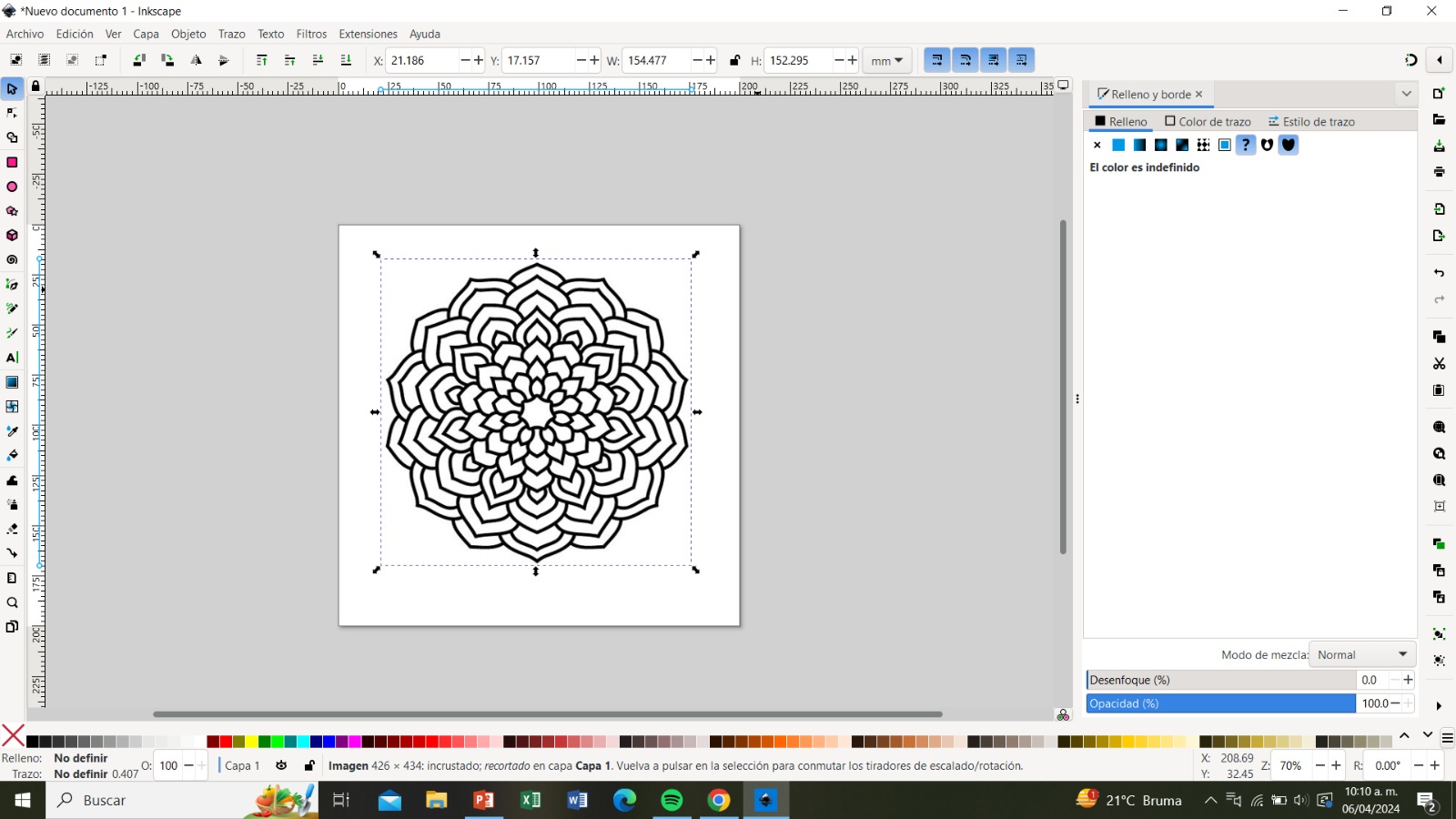
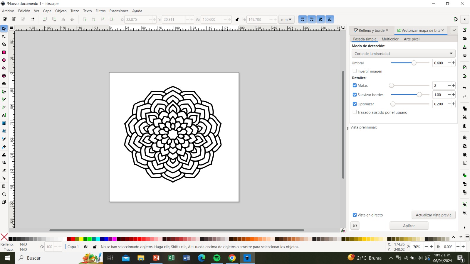
Step 1: In the Inkscape program, we click on the "File" menu and change the document size to match the dimensions of the sand bed so that we can work with the final measurements.
Step 2:
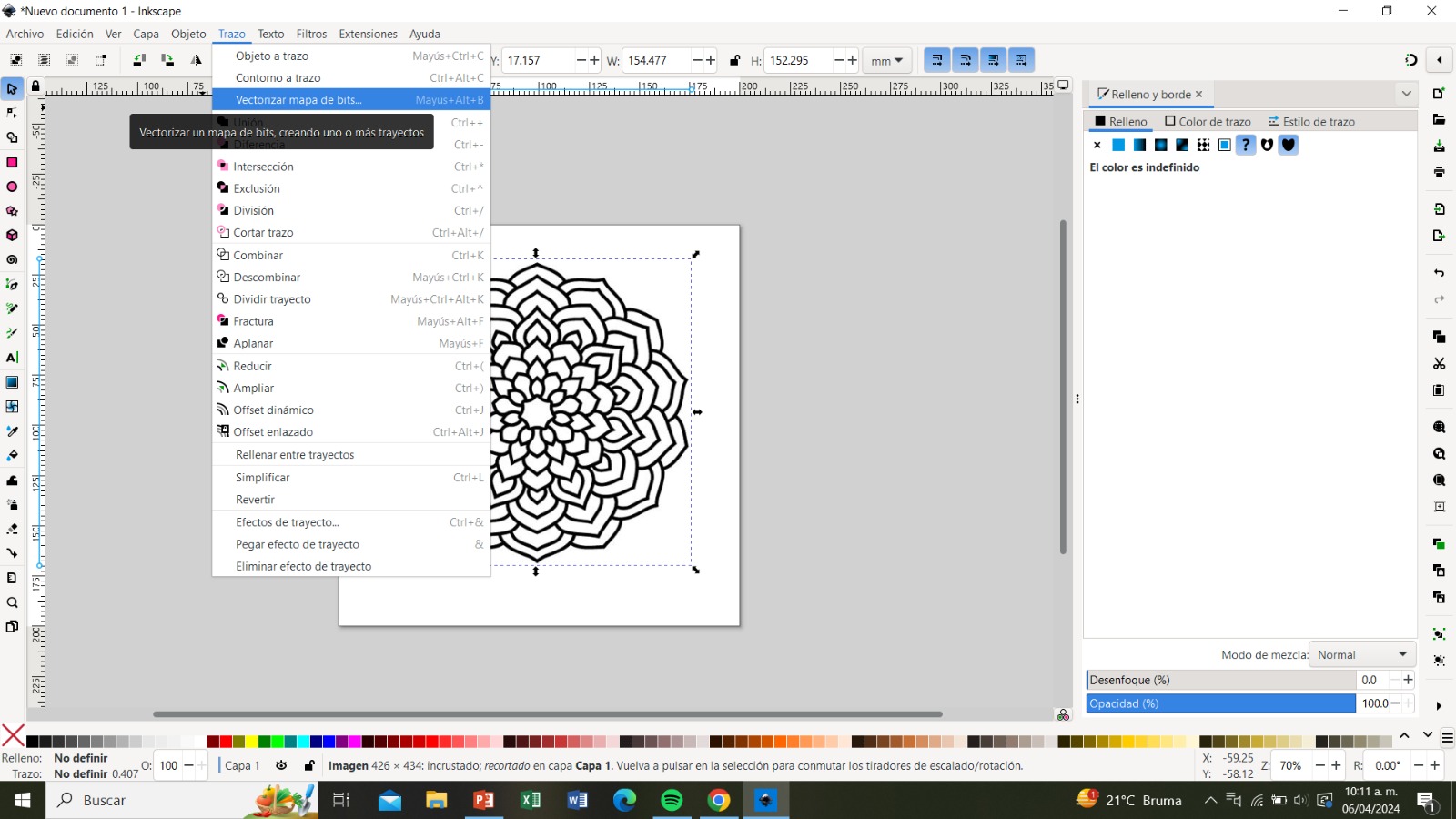
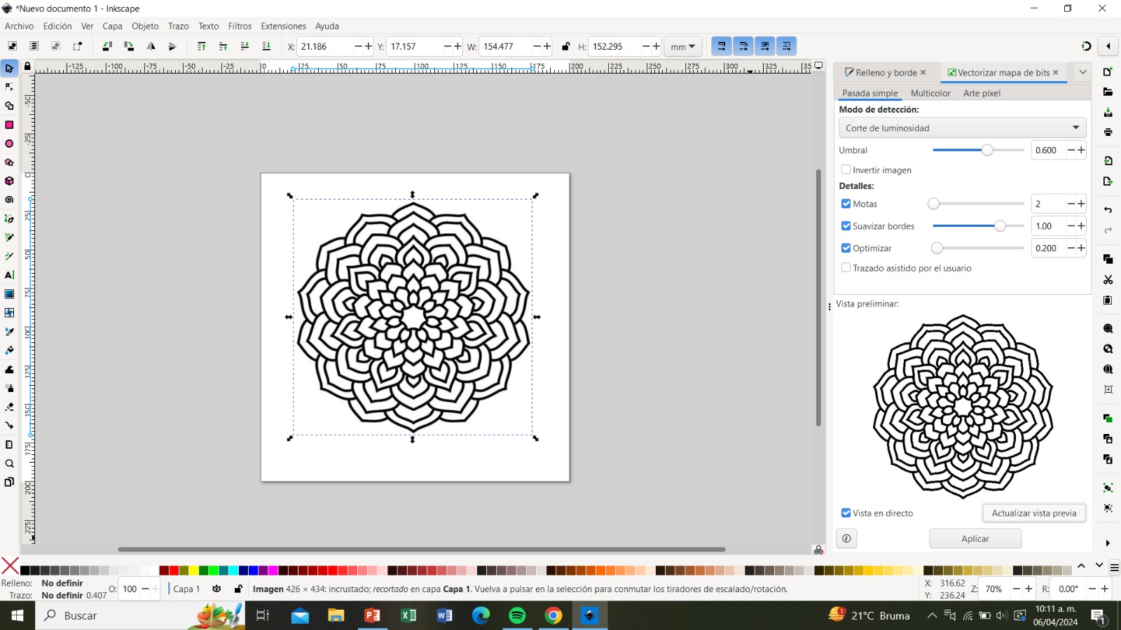
We paste the image we want to be drawn in the sand. Then, under "Trace," we select "Trace Bitmap" to open its menu. From there, we change the threshold to 0.6.
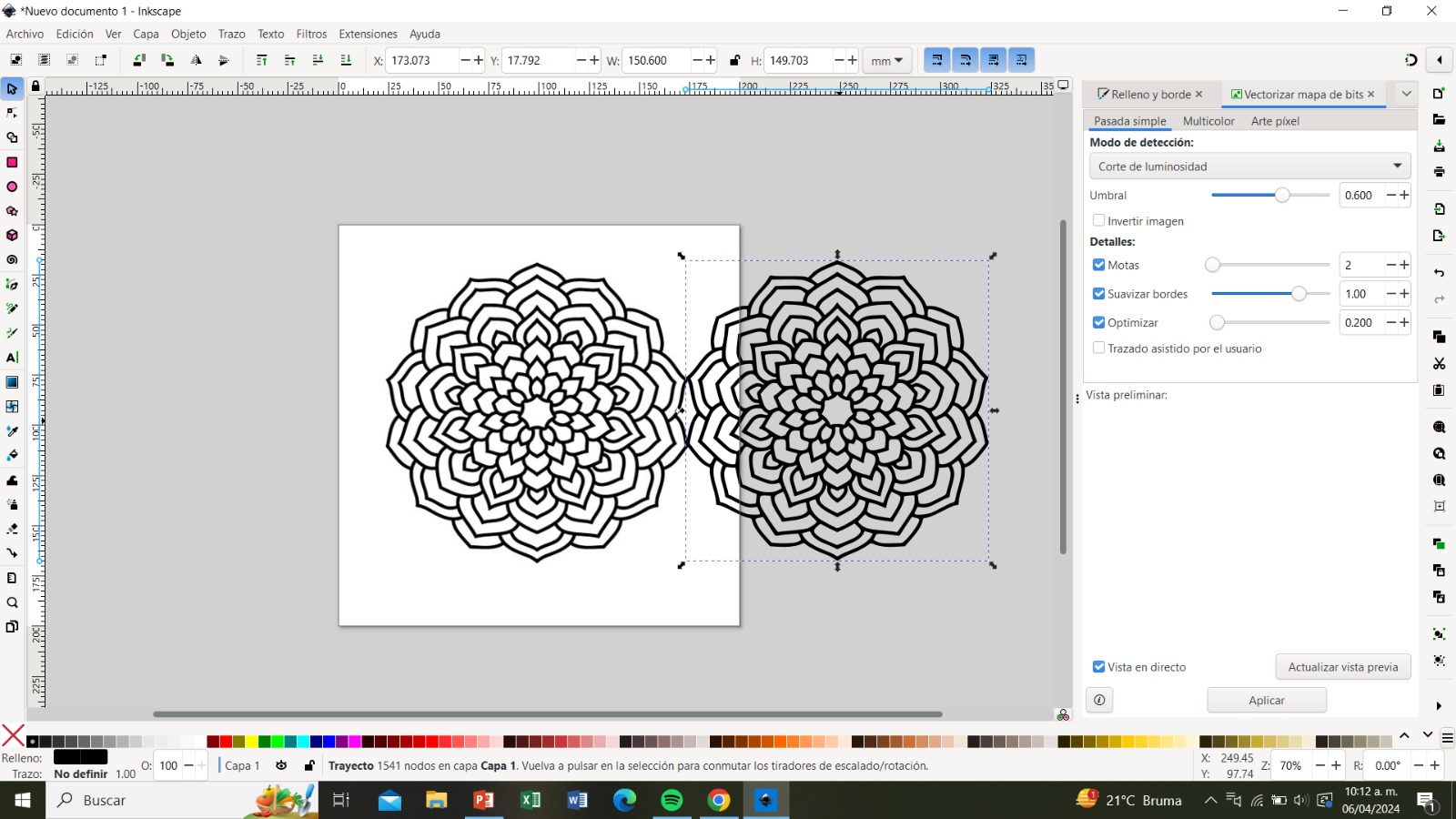
Step 3:
We update the preview and click "Apply". We then drag the trace we just made to remove the previous one.
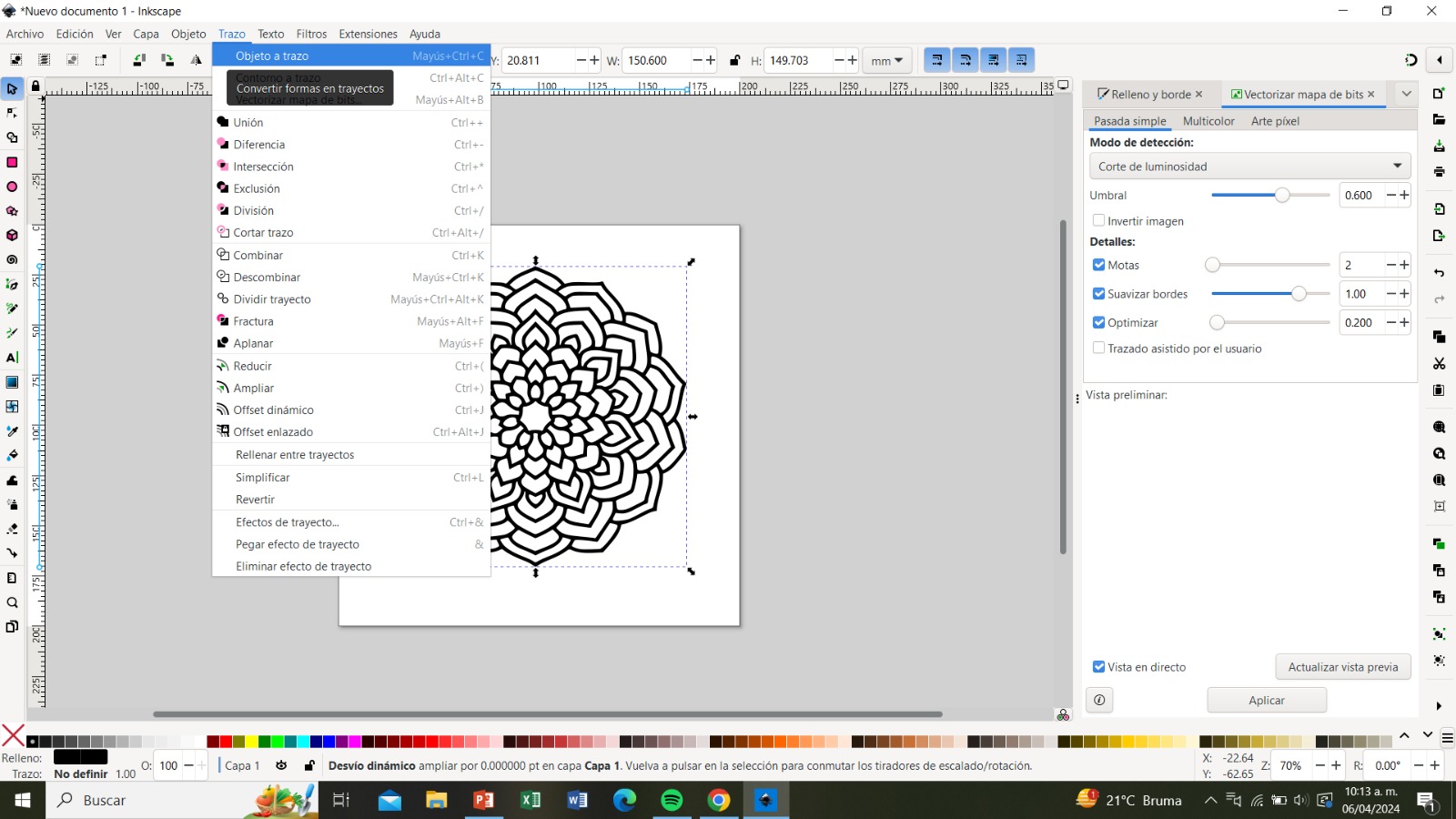
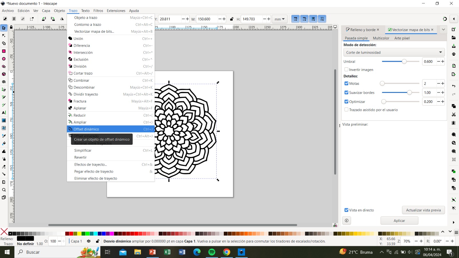
Step 4:
With the new image, we can now generate our G-code. We select the image and under "Trace," we click "Object to Path" and then "Dynamic Offset".
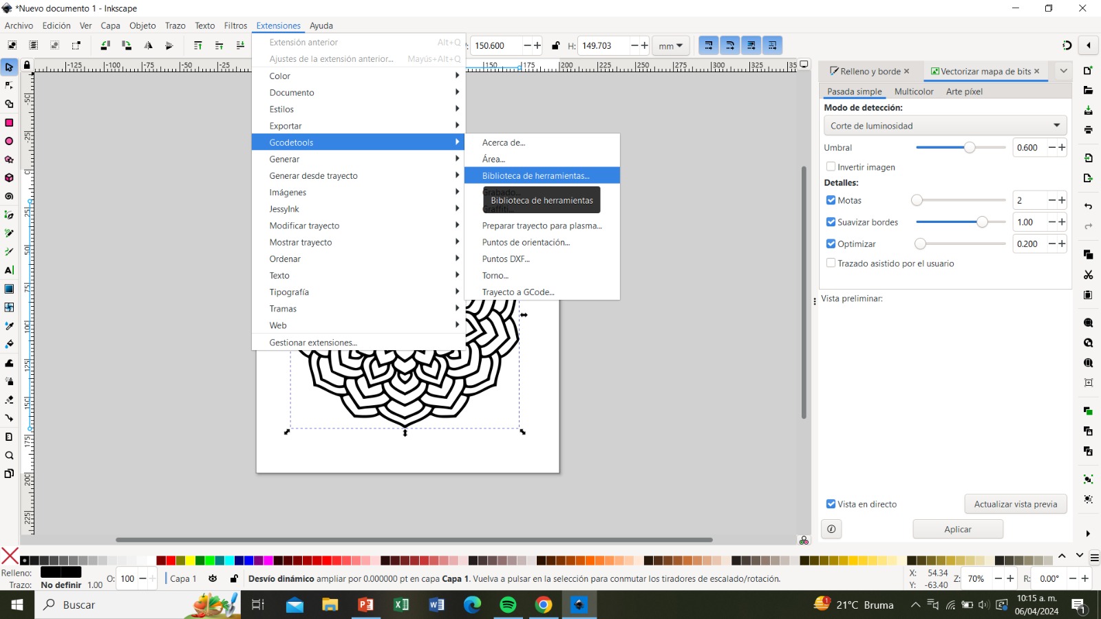
Step 5:
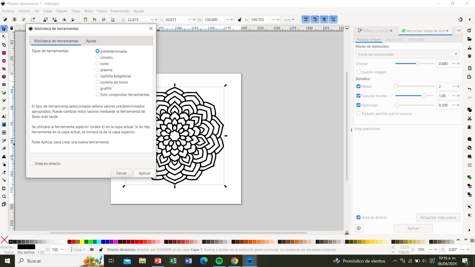
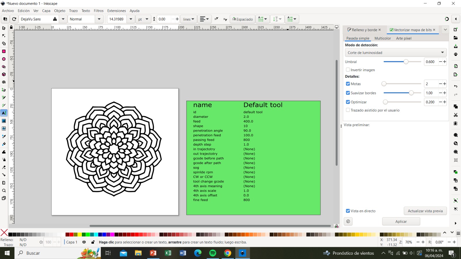
Now, using the Extensions tool, we go to Gcodetools and click on "Tool Library". A menu will open; we ensure that the tool types are set to default and click "Apply". From the opened menu, we change the diameter to 2.0.
Step 6:
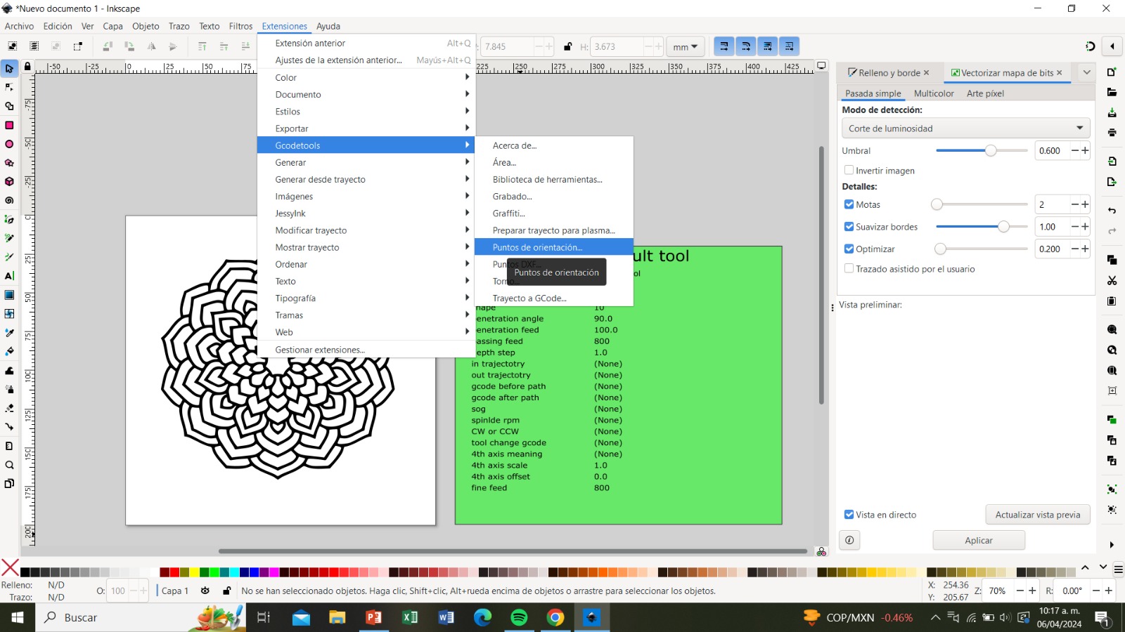
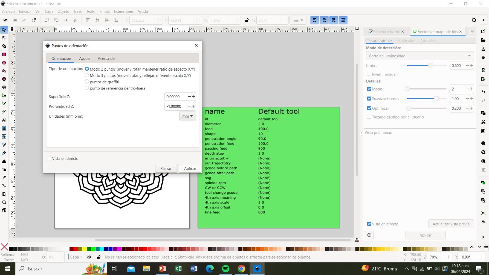
From the Extensions tool, we go to Gcodetools and select "Orientation Points". In that menu, we make sure it's in mode 2 and click "Apply".
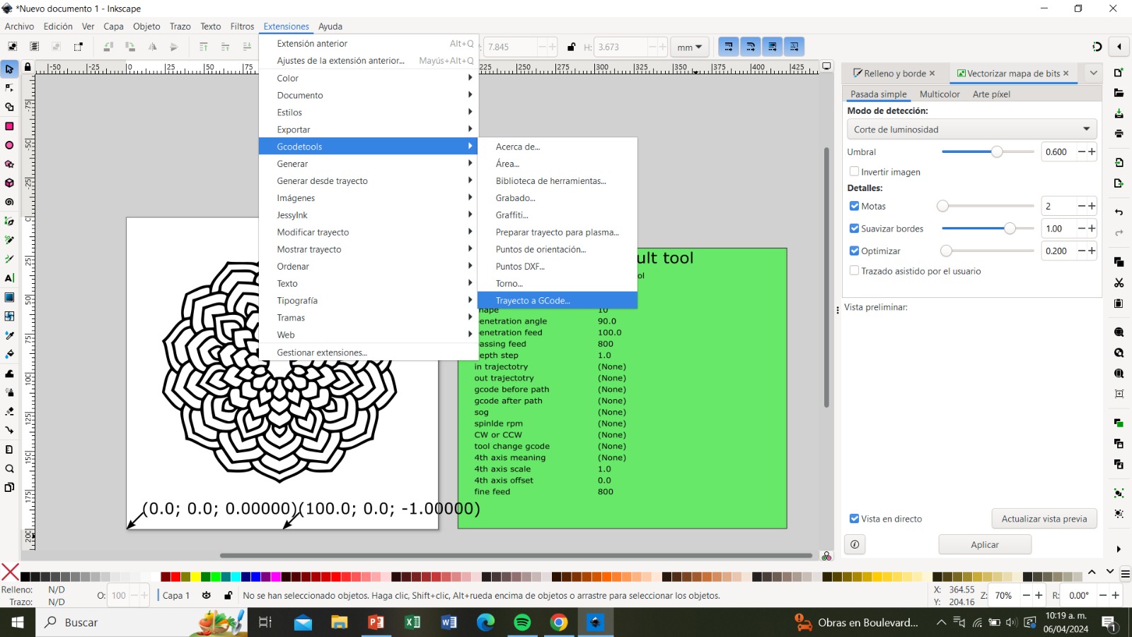
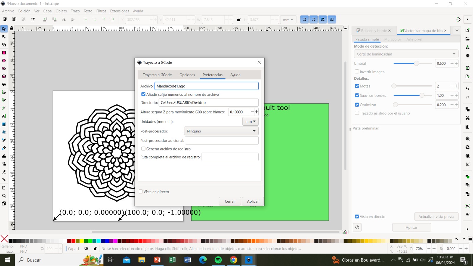
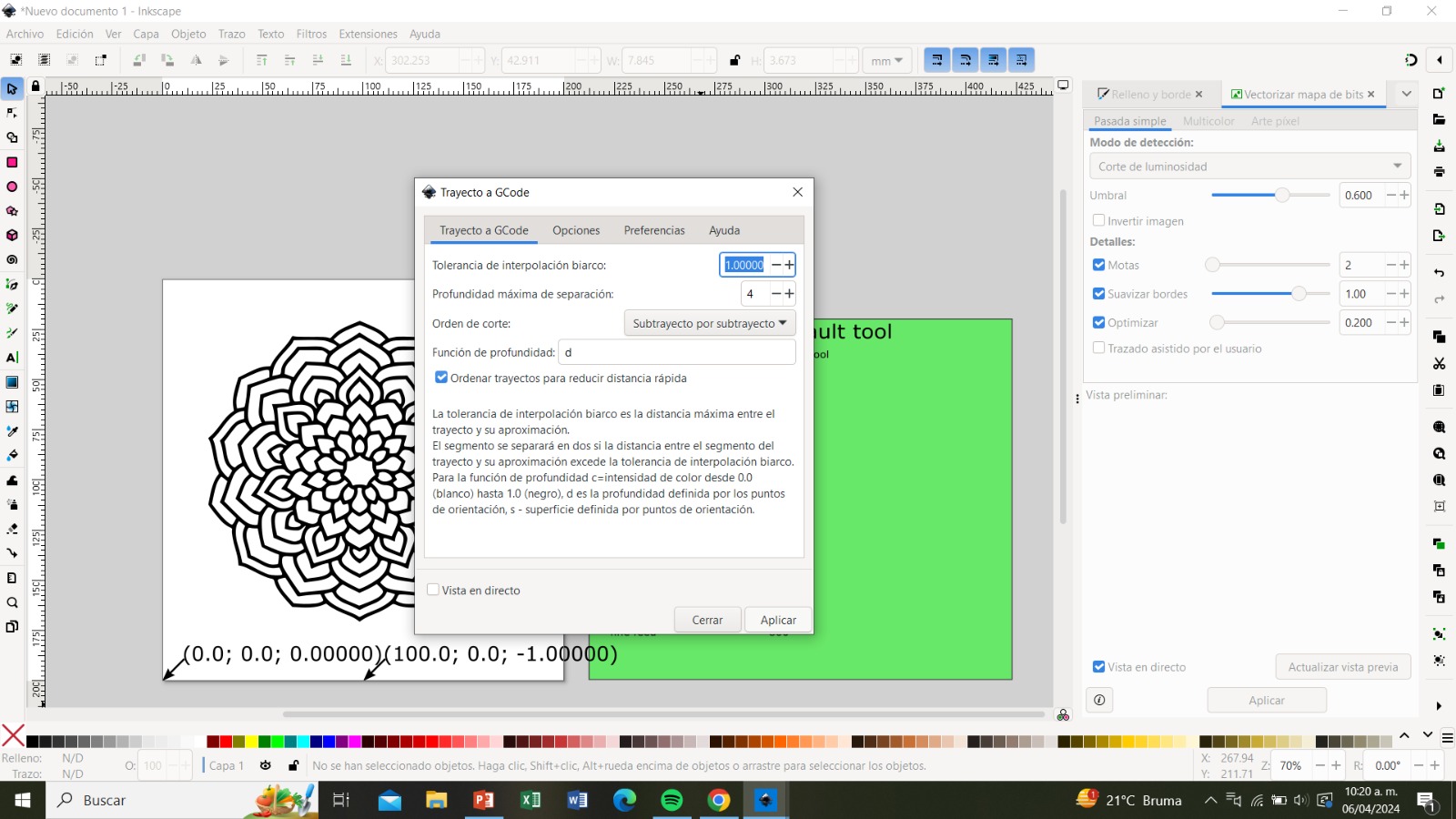
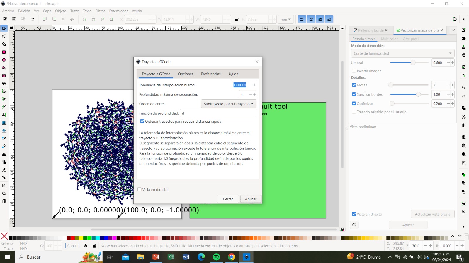
Step 7:
Using the Extensions tool, we enter Gcodetools and select "Path to Gcode". From that menu, we go to preferences and write the name of our file, ensuring it ends in (.ngc). In the directory section, we write where we want to save our document and then click "Apply".