Use the test equipment in the lab to observe the operation of a microcontroller circuit board
(as a minimum, you should demonstrate the use of a multimeter and oscilloscope)
Use an EDA tool to design a development board to interact and communicate with an embedded microcontroller
KiCad.
For this week, use the KiCad software. KiCad is an open-source software for designing electronic circuits and printed
circuit boards (PCBs). It is cross-platform and provides tools for capturing schematics, designing PCBs, and generating
manufacturing files. It is a free alternative to commercial programs and is used by hobbyists and professionals alike.
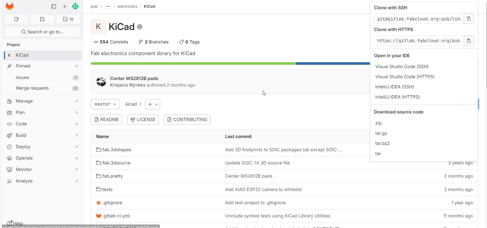
Download the libraries.
First, I downloaded and extracted the Fab Academy components folder.
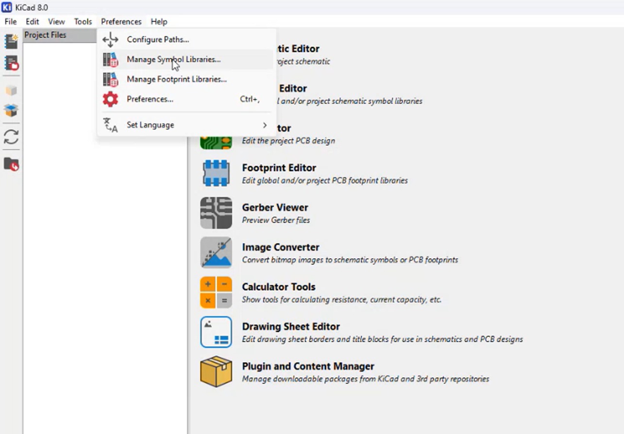
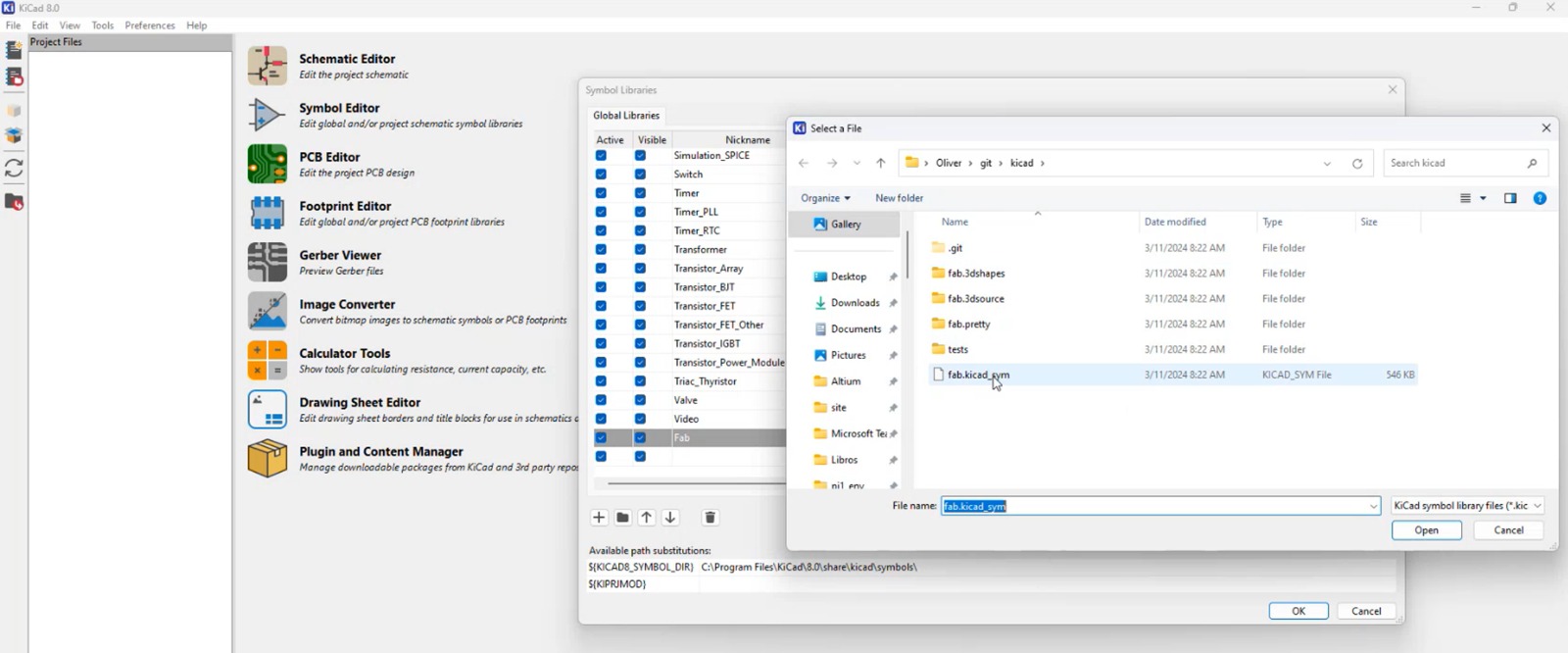
Now we go to "preferences", then to "manage symbol libraries". From there, we create a folder named "Fab", select the downloaded
folder, and choose the "fab.kicad_sym" document.
The same process is repeated for managing "Footprint Libraries" and "Configuring Preferences". We name the new folder for
Footprint Libraries "fab", all lowercase, and select the "fab.pretty" folder.
We now name "FAB" to the new folder in "Configure Preferences", all uppercase, and select the entire downloaded folder.
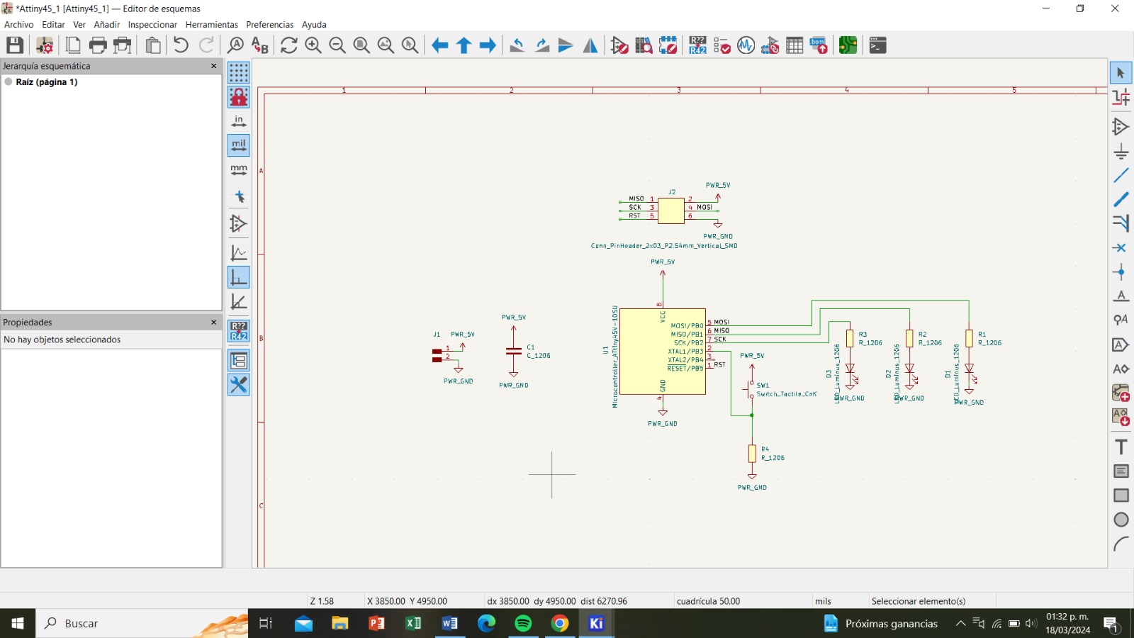
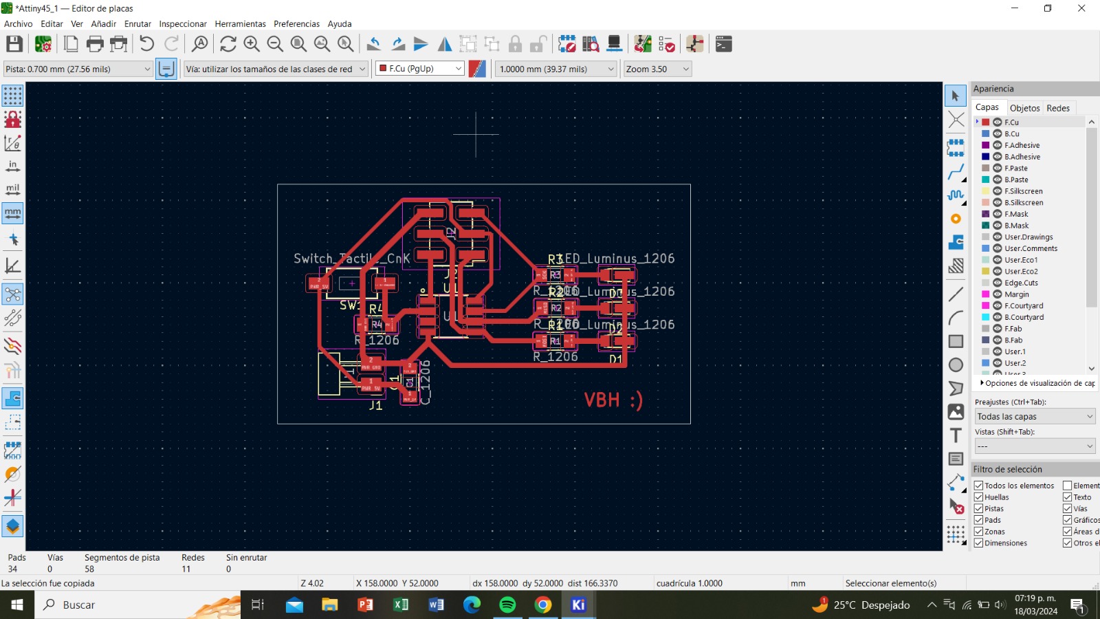
Now we enter the schematic editor and place the components and how they will be connected.
Once we have everything, we can transfer it to the PCB Editor. From there, we arrange the components, make the connections and we create the border."
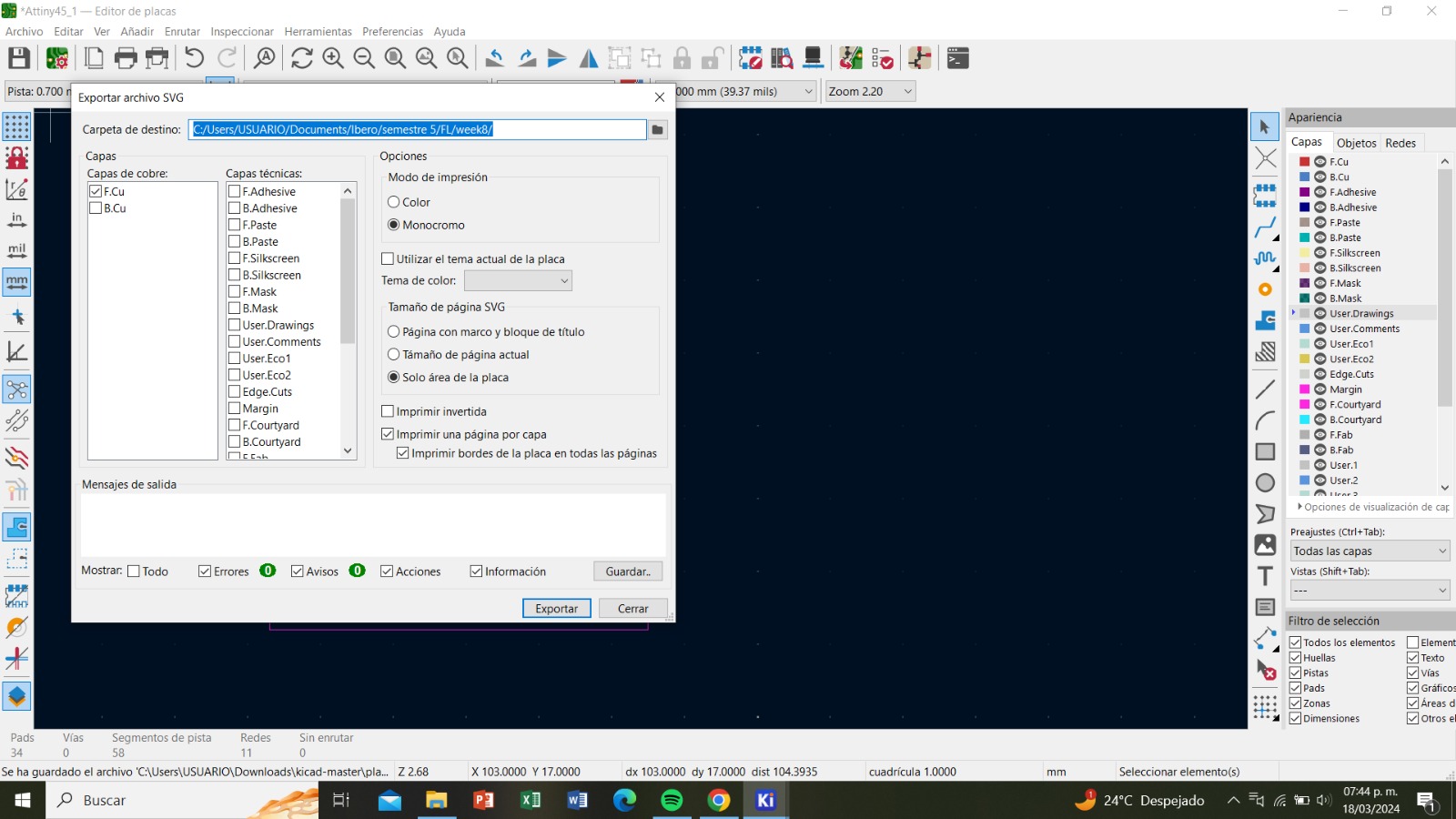
Now we export the first file, which is the inner parts, in SVG format. We select 'F.Cu', 'Monochrome', 'Board area only', and then export
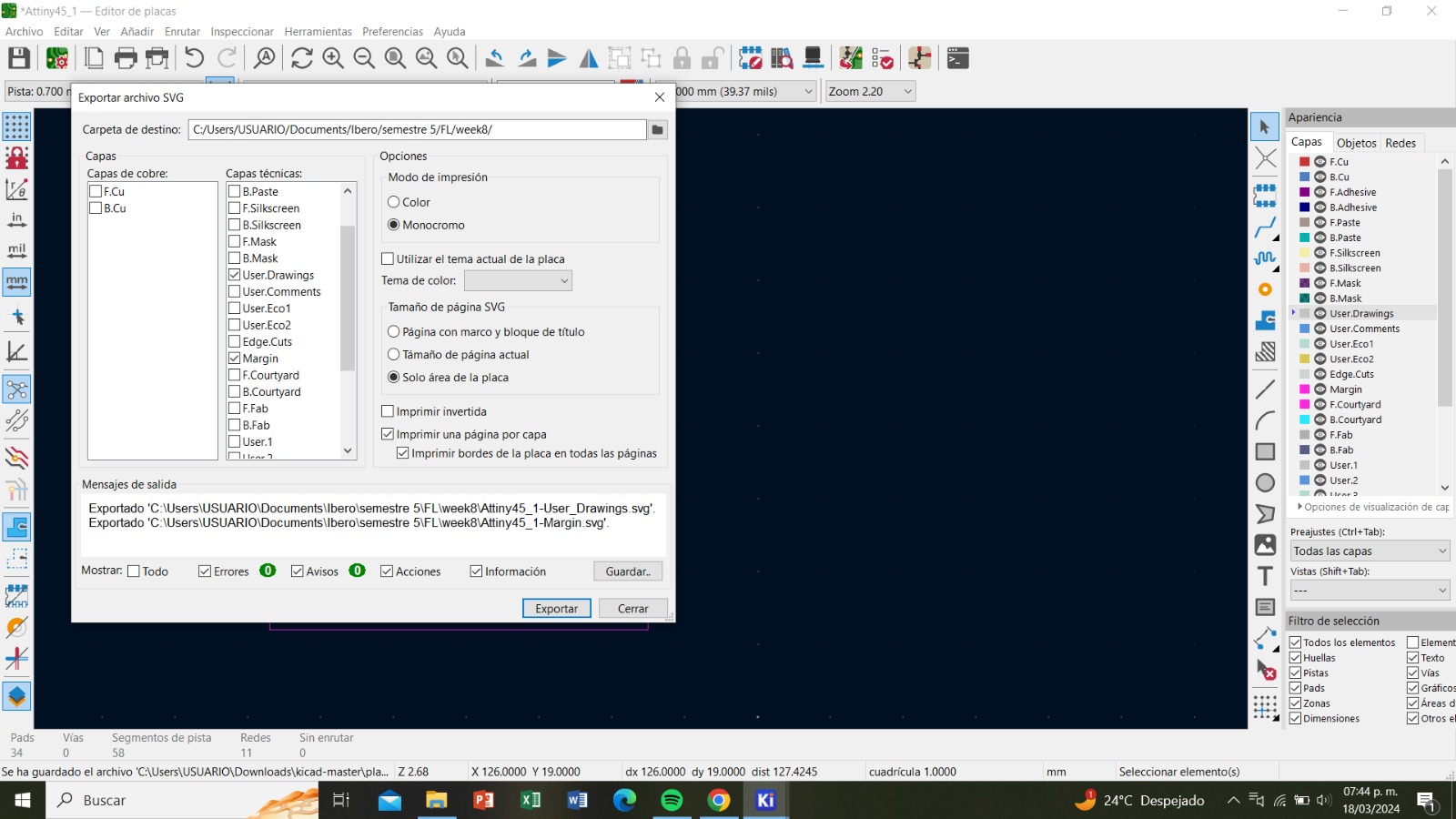
Now, for the outer part, let's also export it as SVG and select 'User.Drawings', 'margin', 'monochrome', 'board area only', and then click 'export'.
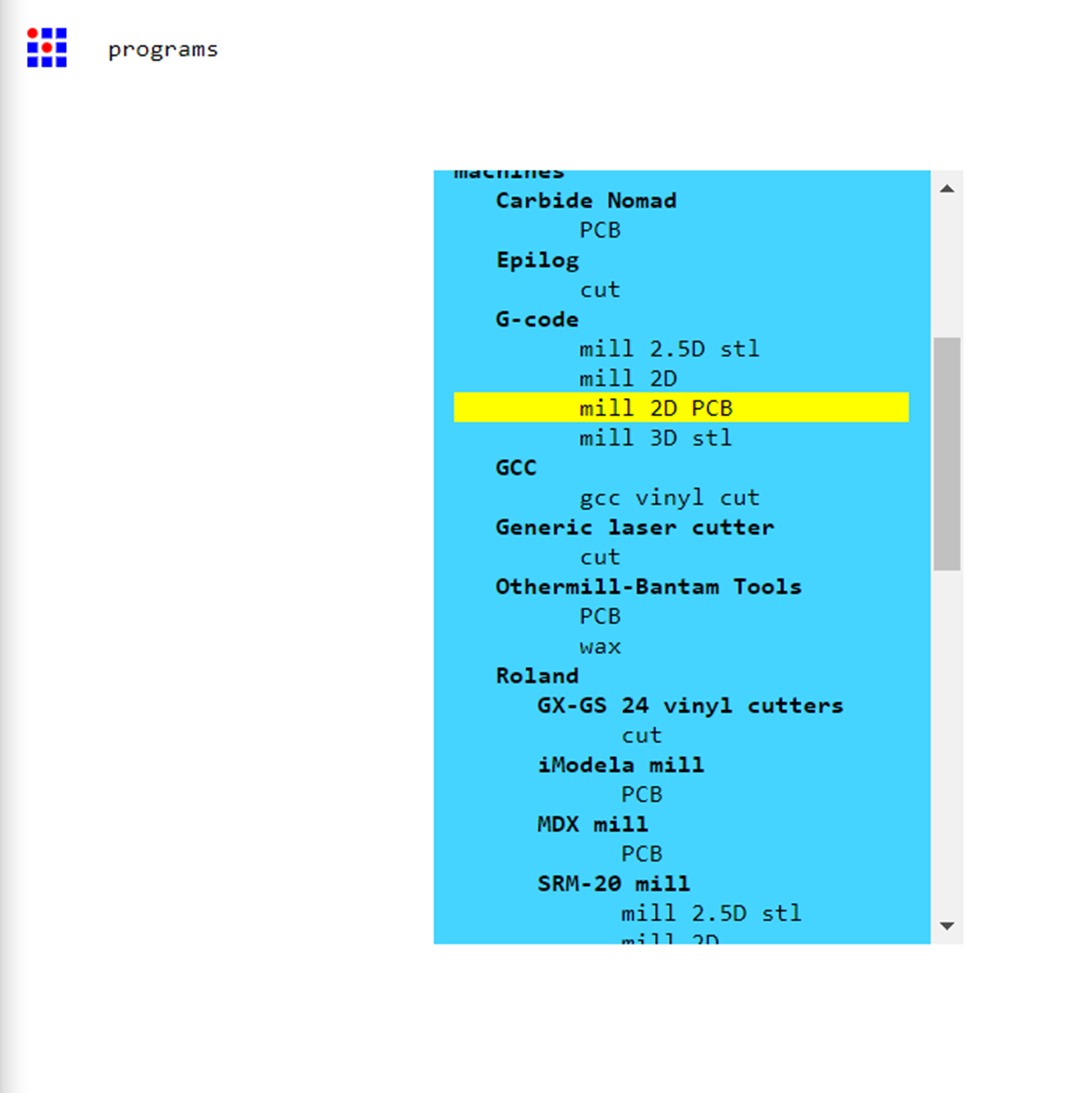
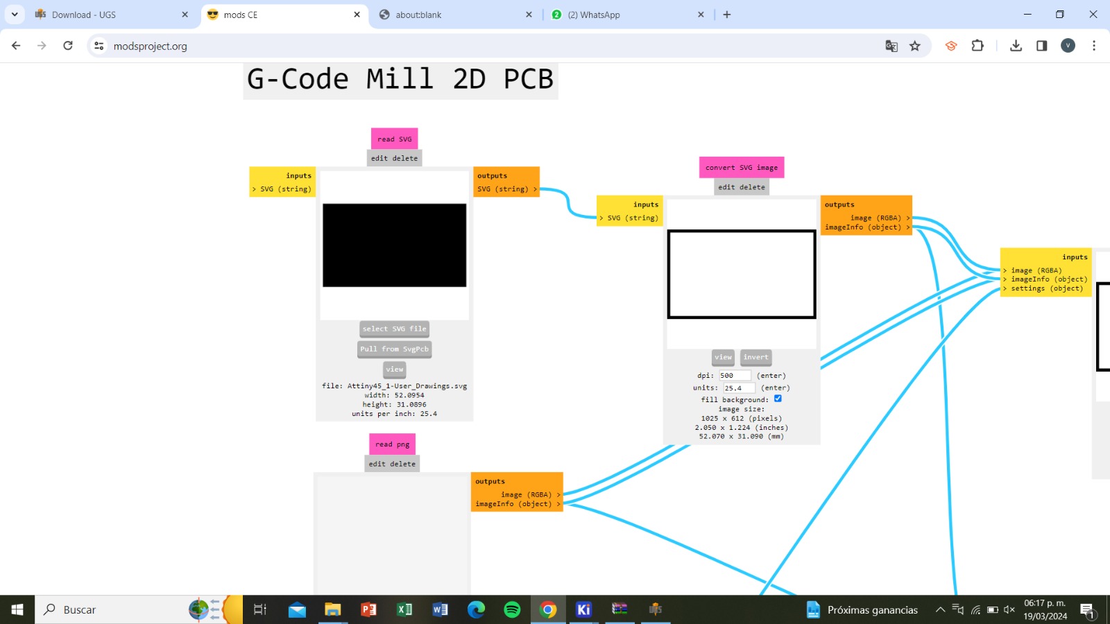
With the documents in SVG format, we can now enter mods. Right-click, select 'Programs', 'Open Program', and choose 'Mill 2D PCB' in G-code.
From there, click on 'Select SVG file' and choose the document of the inner parts. Then, under 'Convert SVG image', select 'Invert'. Next, in
'Mill raster 2D', click on 'Calculate' and save the file. For the outer part, repeat the same process.
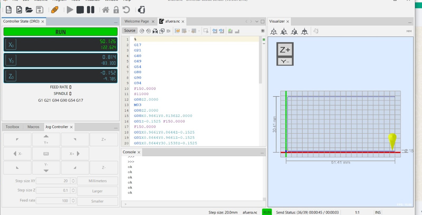
Now we need to download UGS to control the machine. We open the program and select 'File', 'Open', and choose the document for the inner parts. Within the program, we select the origins for 'Y', 'X', and 'Z', and then click 'Play'.
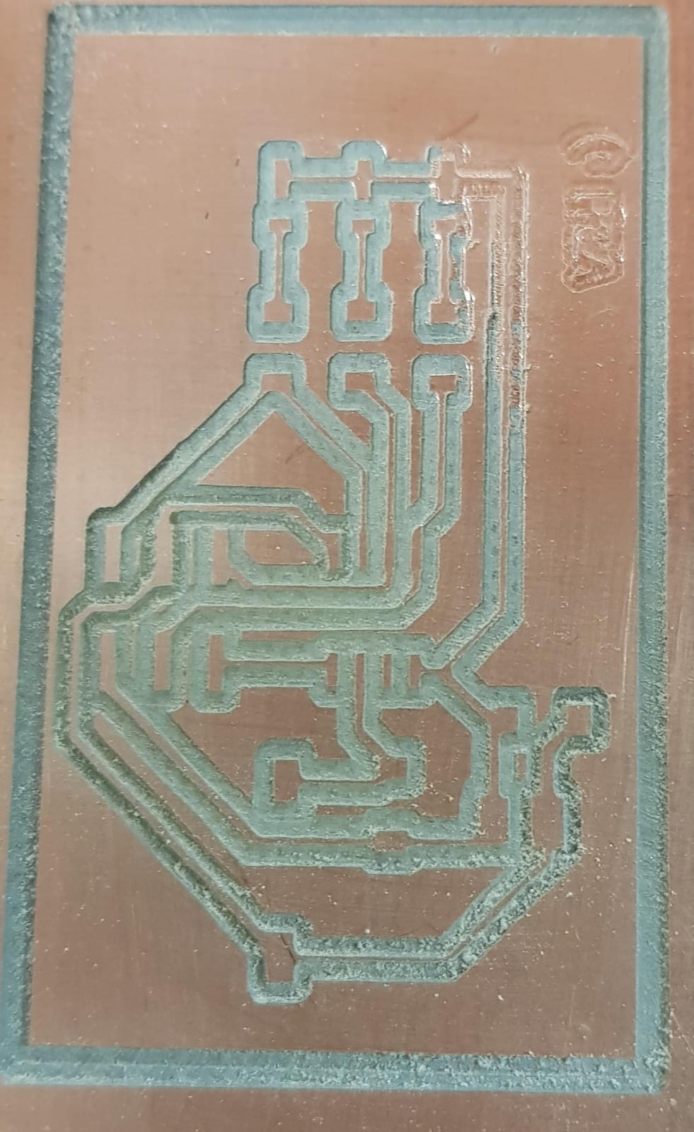
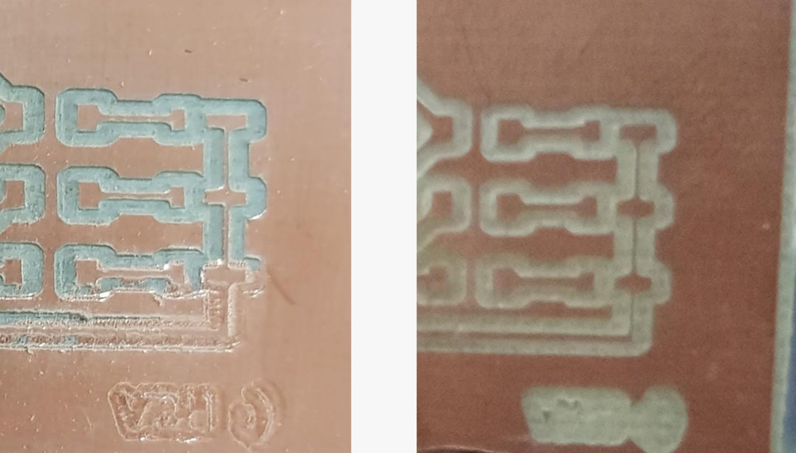
As you can see in the image, some tracks were not marked correctly, so I will cut it again. Here is the before and after:
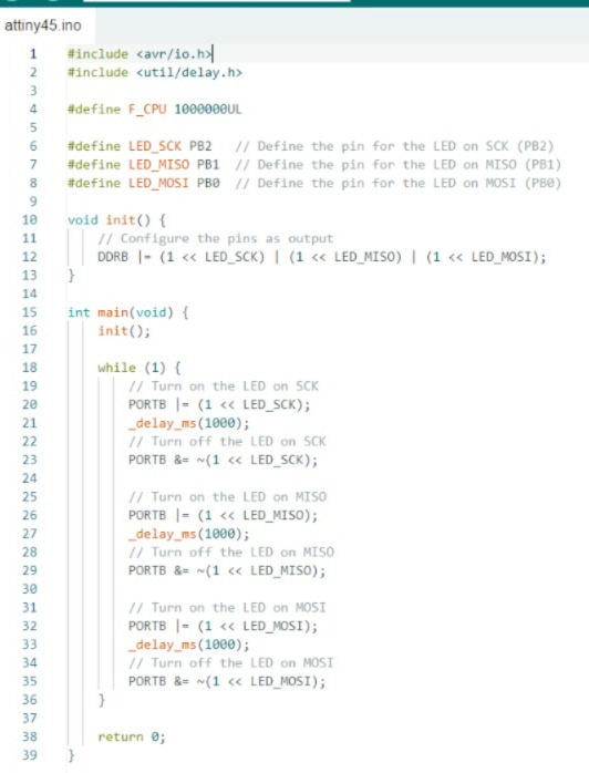
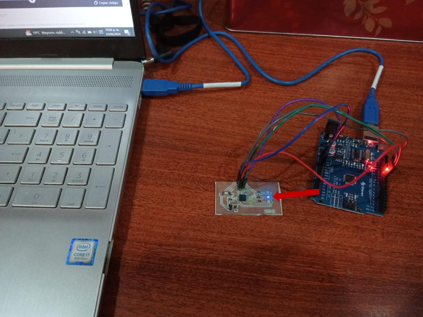
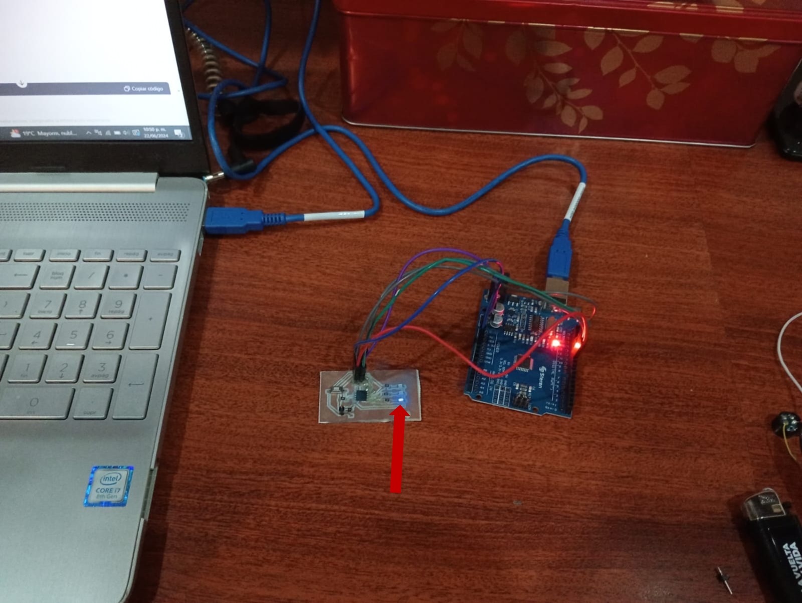
Now I just have to solder it and upload a code. What I want the board to do is to first light up the SCK
LED and turn it off, then light up and turn off the MISO LED, and finally light up the MOSI LED.
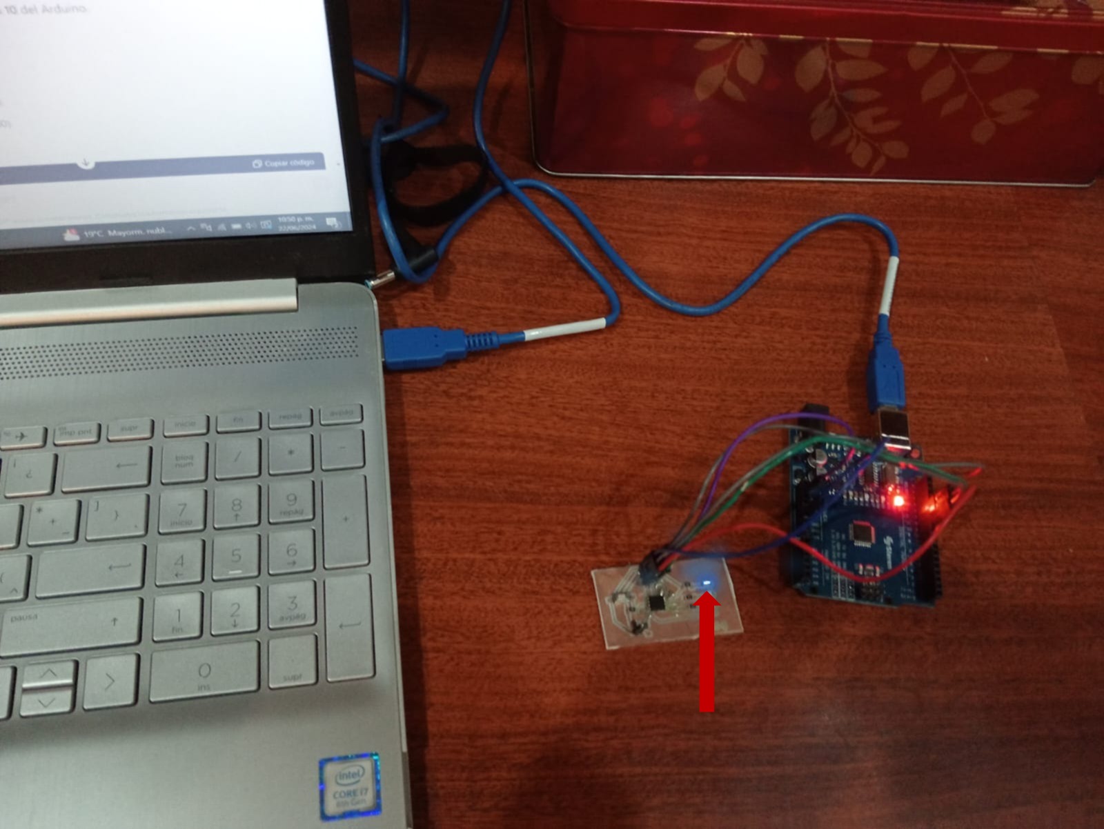
I will connect the ATtiny45 to an Arduino for programming and powering it.
First, I will make the connections.
-Vcc (Pin 8) of the ATtiny45 to 5V on the Arduino.
-GND (Pin 4) of the ATtiny45 to GND on the Arduino.
- (Pin 5) of the ATtiny45 to Pin 11 on the Arduino.
- (Pin 6) of the ATtiny45 to Pin 12 on the Arduino.
- (Pin 7) of the ATtiny45 to Pin 13 on the Arduino.
- (Pin 1) of the ATtiny45 to Pin 10 on the Arduino.
Then, we have to set up the Arduino as an ISP.
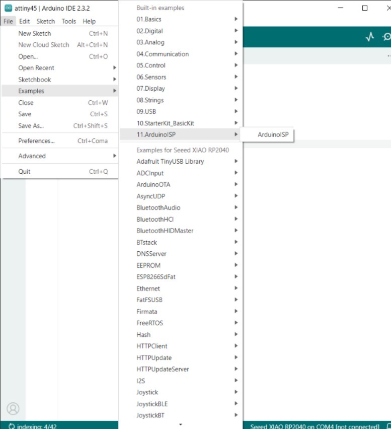
1.- Open the Arduino IDE.
2.- Load the "ArduinoISP" sketch located at File > Examples > 11.ArduinoISP > ArduinoISP.
3.- Select the board corresponding to the Arduino you are using ("Arduino Uno").
4.- Select the port corresponding to the Arduino.
5.- Upload the sketch to the Arduino.
Now, we have to configure the ATtiny45 in the Arduino IDE and download it.
Add the ATtiny board manager:
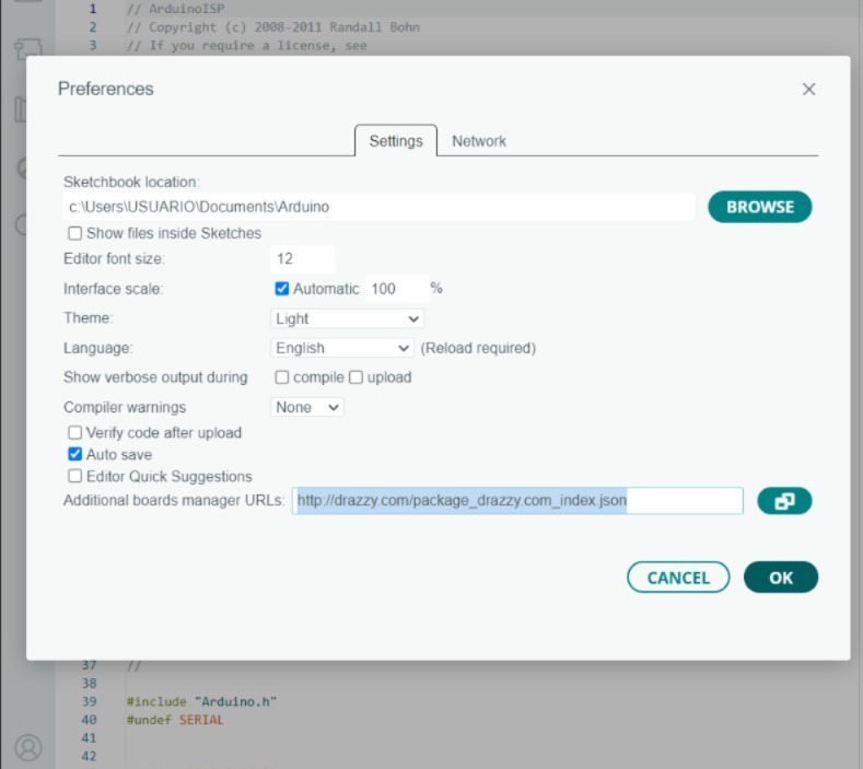
-Go to File > Preferences.
-In the "Additional Board Manager URLs" section, add http://drazzy.com/package_drazzy.com_index.json.
-Go to Tools > Board > Board Manager.
-Search for "ATTinyCore" and install the package.
Select the ATtiny45 board:
-Go to Tools > Board > ATtiny45/85.
-Under "Processor", select ATtiny45.
-Under "Clock", select 1 MHz (internal).
-Under "Programmer", select Arduino as ISP.
Upload the code to the ATtiny45:
Write or open the code you want to upload to the ATtiny45.
Go to Tools > Burn Bootloader (only needs to be done once to set the fuses).
Go to Sketch > Upload Using Programmer.
The code will be uploaded to the ATtiny45 through the Arduino.
The code is as follows:
And it's done. When running the code, the LEDs turned on very dimly :(