For this week, we need to characterize the design rules for our in-house PCB production process:
document feeds, speeds, plunge rate, depth of cut (traces and outline) and tooling. Document the
workflow for sending a PCB to a board house.
In FabLab Puebla, there are three different models of Mini-Mill. These compact yet powerful tools
function by translating digital designs into physical circuit boards. Here's how they work: a high-speed rotary
cutter is used to remove unwanted copper from a copper-coated substrate, accurately creating pathways that form the circuit.
Unlike larger CNC machines, these mini-mills are optimized for the fine details required in PCB work, using advanced
software to control the milling process. This software directs the cutter's movement based on PCB design files, ensuring
that each cut is precise and matches the circuit design exactly. The result is a cleanly milled PCB, ready for soldering
components and testing for rapid prototyping.
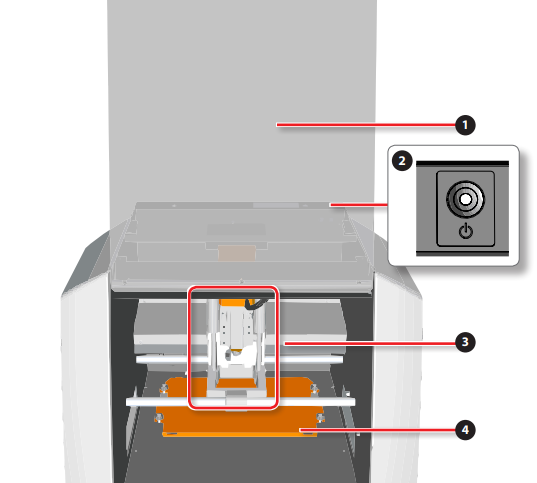
The Mini Mills operate like a CNC, making their parts easy to identify.
Front Cover: This is the protective shield that covers the front part of the mini mill.
It helps to safeguard the user from debris and provides a safety barrier between the
milling process and the operator.
(Power) Button: This is the main power switch for the machine. It allows the user to turn
the mini mill on or off.
Spindle Head: The spindle head houses the spindle motor and is the part of the machine
that moves in various axes to mill the PCB material. Here’s where the tool will be mounted
Working Table: his is the flat surface where the PCB material is secured before the milling
process begins. The table moves along different axes to position the material correctly
under the spindle head for precise milling.
Spindle Rotation Speed: Adjustable from 3,000 RPM to 7,000 RPM
Interface: USB
Operational Noise: During operation: 65 dB(A)
External Dimensions: 451 mm (width) × 426.6 mm (depth) × 426.2 mm (height)
(17.76 in [width] × 16.80 in [depth] × 16.78 in [height])
Weight: 19.6 kg
Besides the cutter,some other things are needed to create our PCB such as:
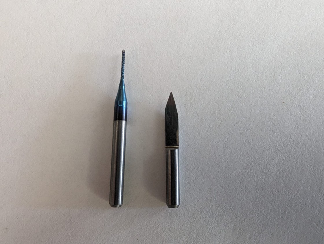
Tooling
A PCB milling requires repeatability and precision for fine details.
so for engraving we're using a 15 degree V-bit and for cutting we're using a 0.8 mm diameter two flute end Mill.
Design of the circuit:
To generate the GCode for the circuit, we have to use 'modes CE' as it has a program already made for the SRM-20 Mill specifically for PCBS.
For this week, the individual assignment is to make and test a microcontroller development board.
Program download
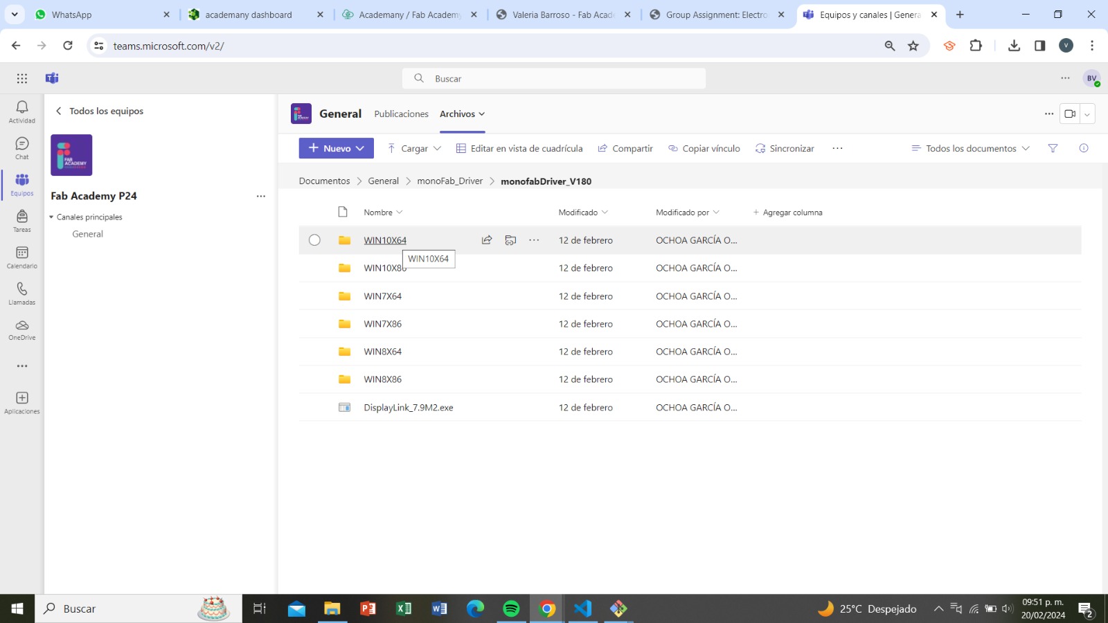
First, to download the VPanels program, a program that allows us to operate the cutter from our computer,
we need to download the folder that is compatible with our computer, in my case it's the WIN10X64.
This folder was given to us by the advisors.
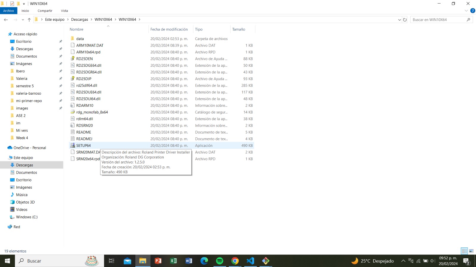
From the folder, we select SETUP64 and download it.
Once we have the SETUP, we download the VPanel program.
Likewise, the download link was provided by the advisors
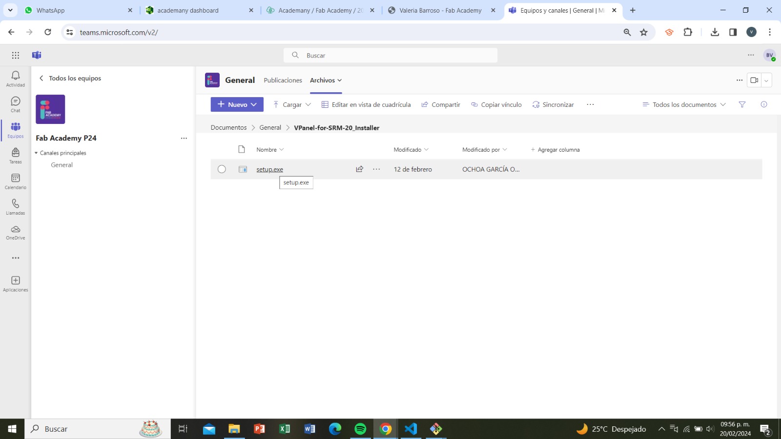
Mods
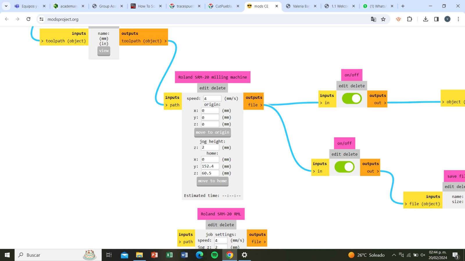
Now, from mods, we right-click, select 'programs', then 'open program', and then search for Roland,
because it's the machine we're working with, and select 'mill 2D PCB'. And it will look like this:
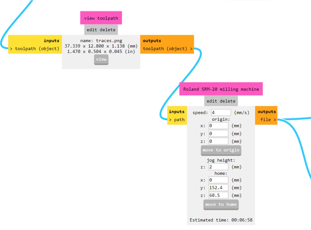
We zoom in on 'Roland SMR-20 milling machine' and change the default values of 'x', 'y', and 'z' to 0. We also switch both switches to 'on'.
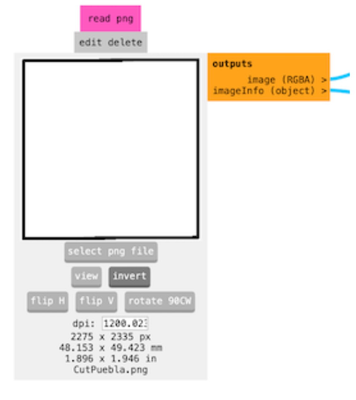
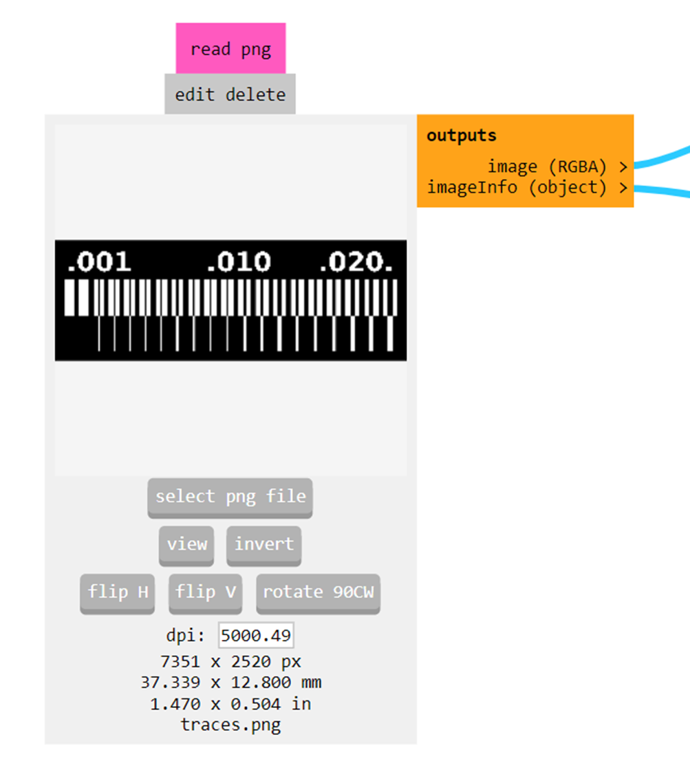
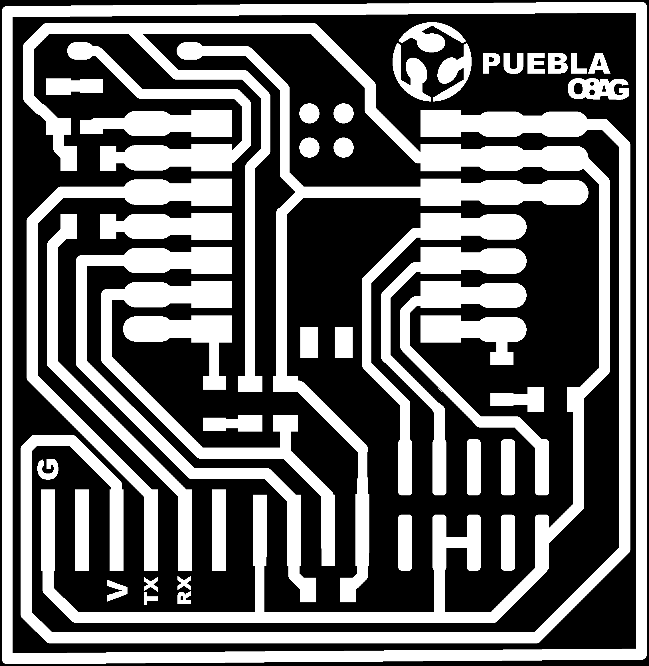
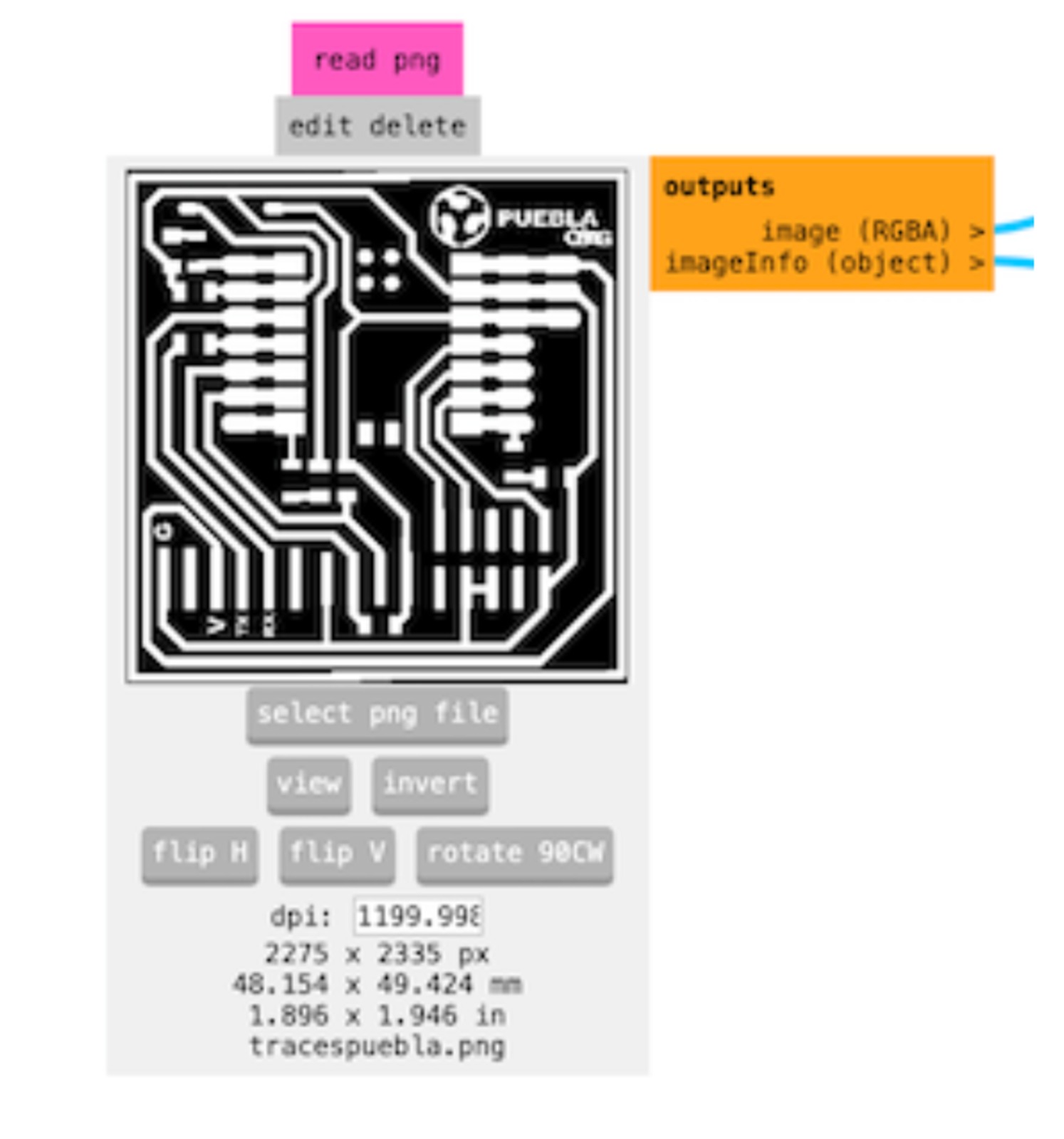
Then, in the section of 'read PNG edit delete', we click on 'select PNG File' and choose the image
"PROGRAMER TRACES"
We have to do the same for the contour cutting.
"PROGRAMMER CUT OUT"
But for this case, we need to invert the image so it cuts the black lines.
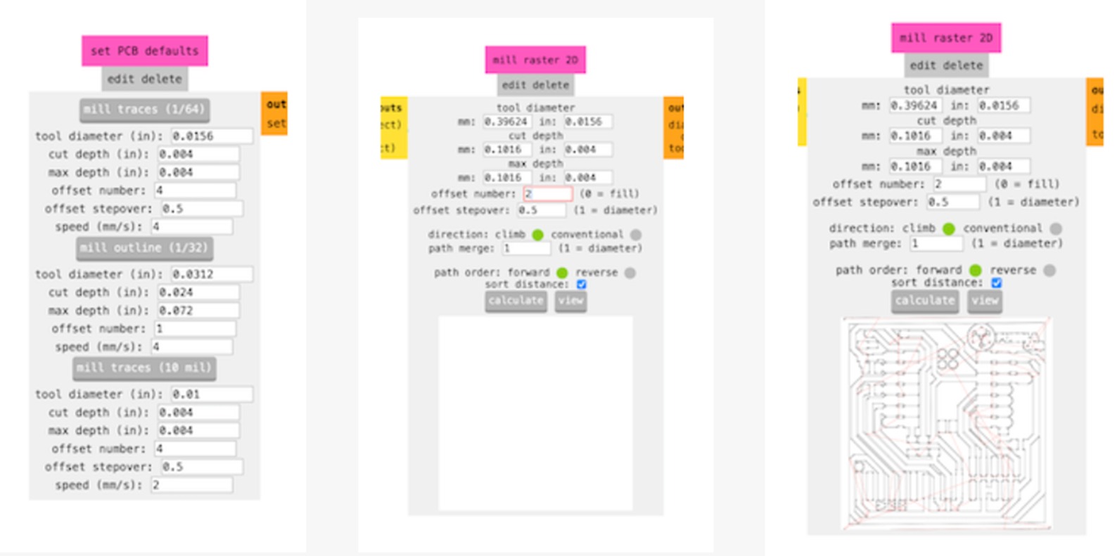
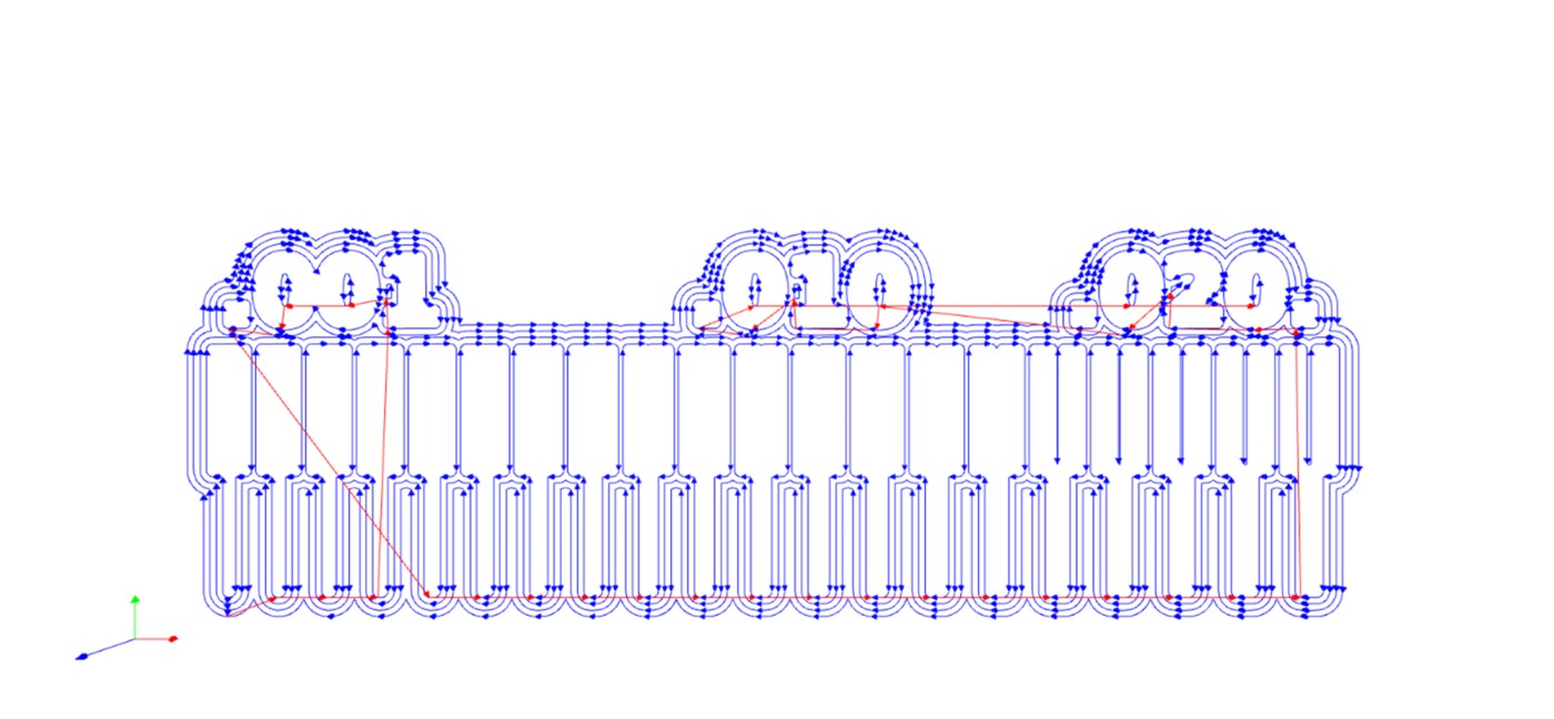
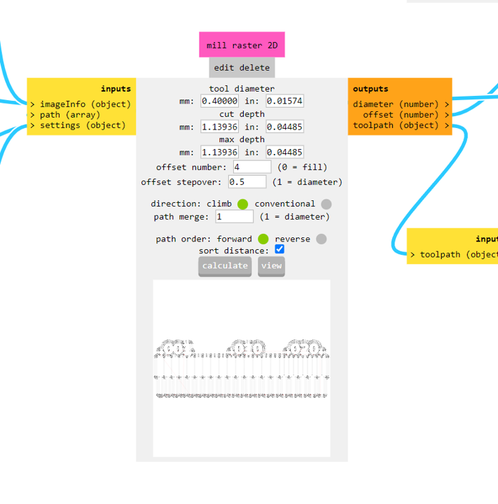
Now we have to change some parameters, the first one we do it in "set PCB defaults", here we have to make sure
that "mill traces" is set to 1/64". In the section of "mill 2D" we change the "offset number" to 2. Finally, in
"mill raster 2D" we select "calculate" to generate the document in .rml format.
Board cutting
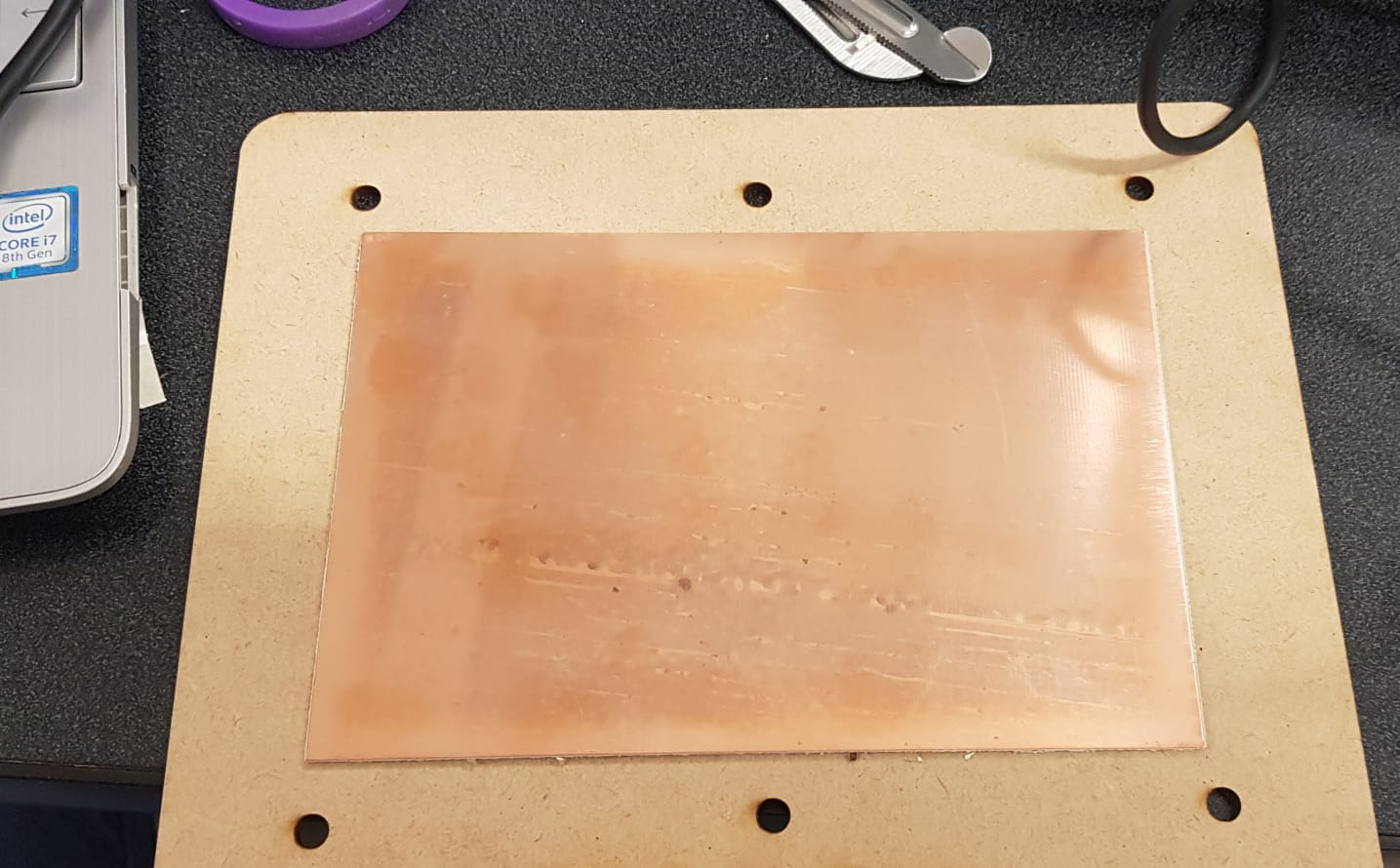
Having both documents ready, we can now cut. But first, we need a "sacrificial bed,"
which is an MDF table to
protect the machine's aluminum. We cut it and then attach a copper plate with double-sided tape.
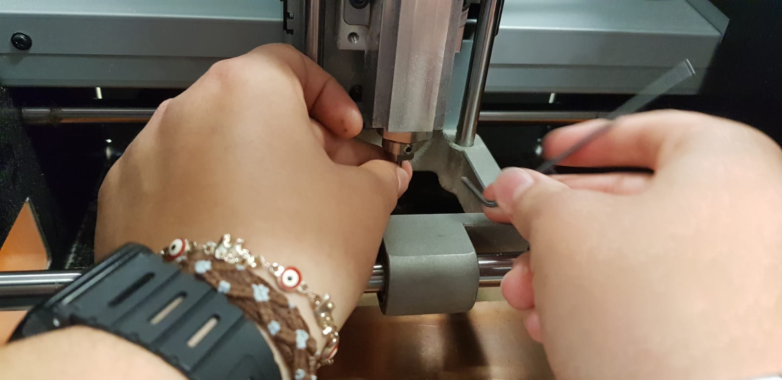
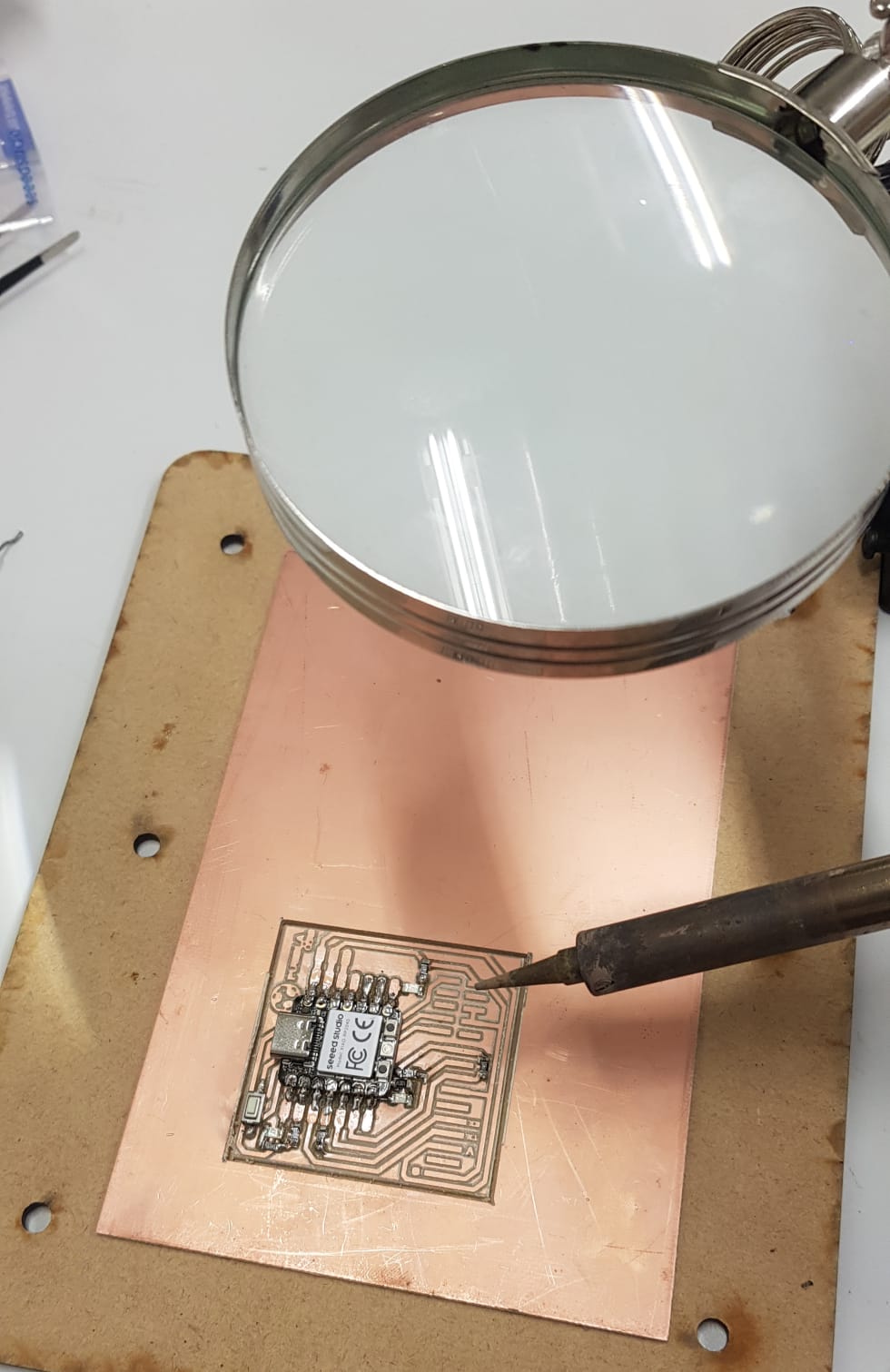
We install the sacrificial bed on the machine, ensuring that all screws are properly secured, and we place the drill bit in its place.
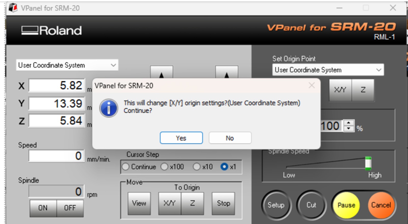
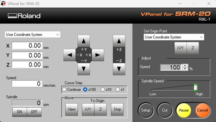
Now, we connect our computer to the machine and with the controls adjust the parameters for the "x" and "y" axes in the lower corner of the plate.
For the z-axis, we need to ensure that the drill bit makes contact with the plate without applying too much pressure,
and we save the position with the x/y and z buttons on set origin point.
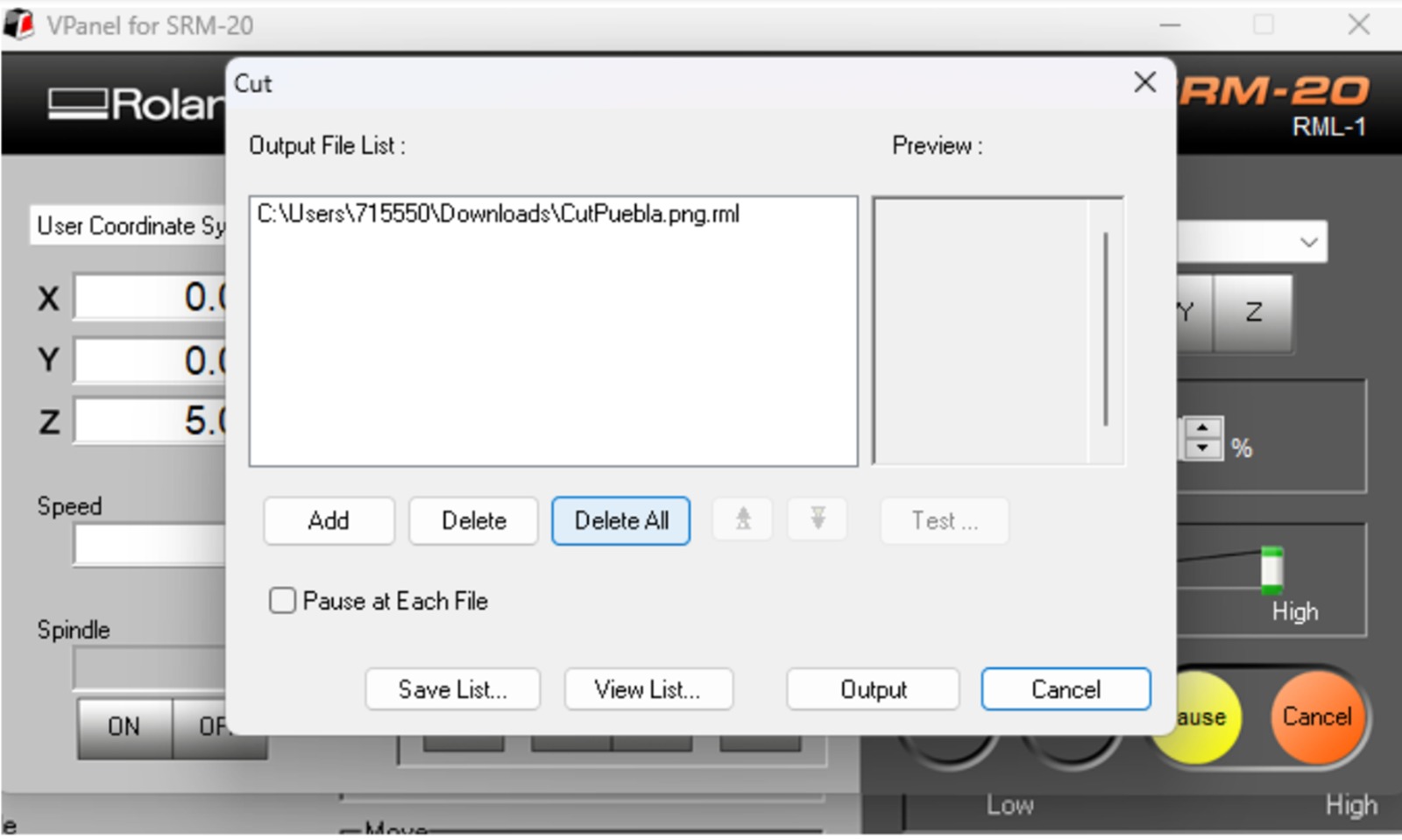
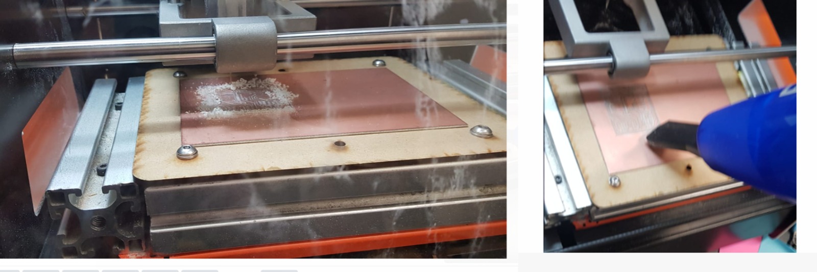
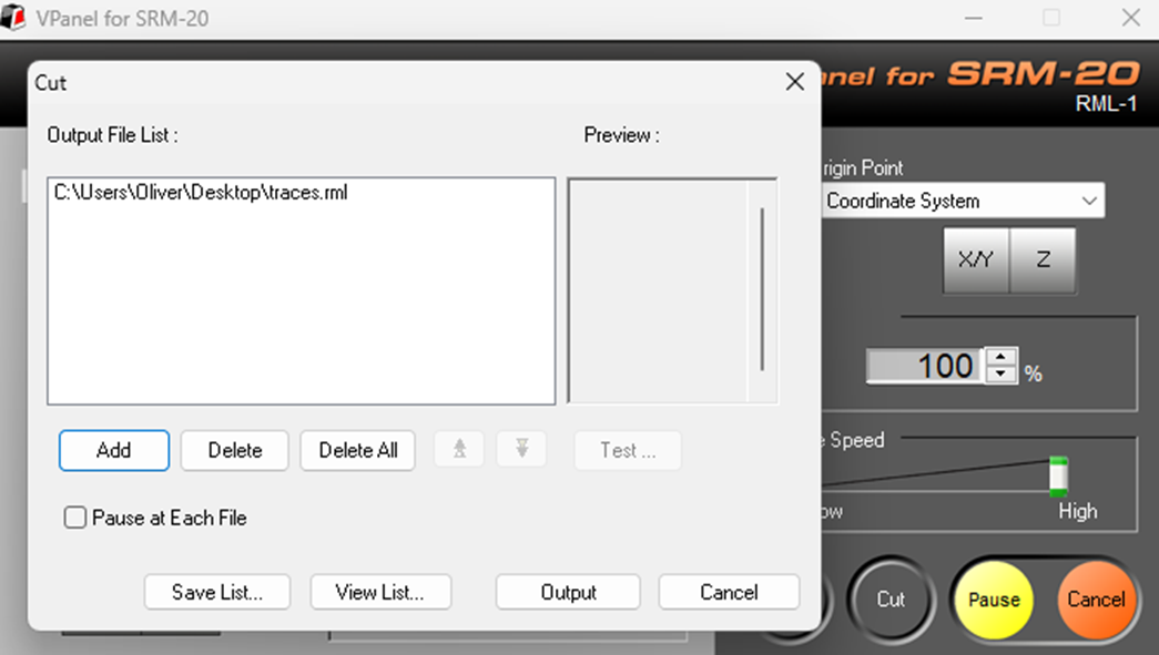
Now, we click on "cut," then "add," and first choose the document "PROGRAMER TRACES," we cut it,
and after the machine finishes, we cut the document "PROGRAMMER CUT OUT" as well.
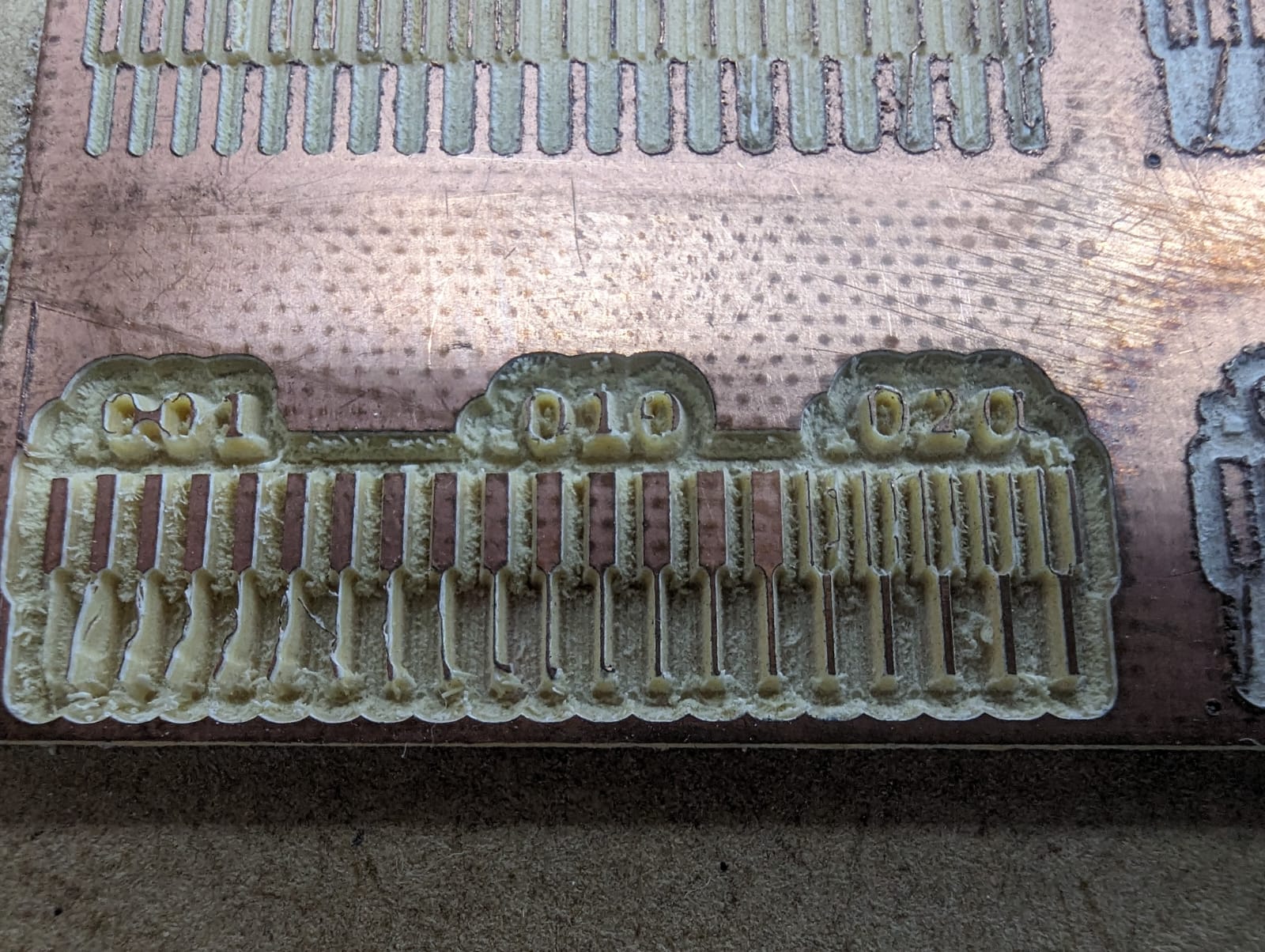
After finishing the cutting process, we open the gate and vacuum up the excess material.
Board soldering
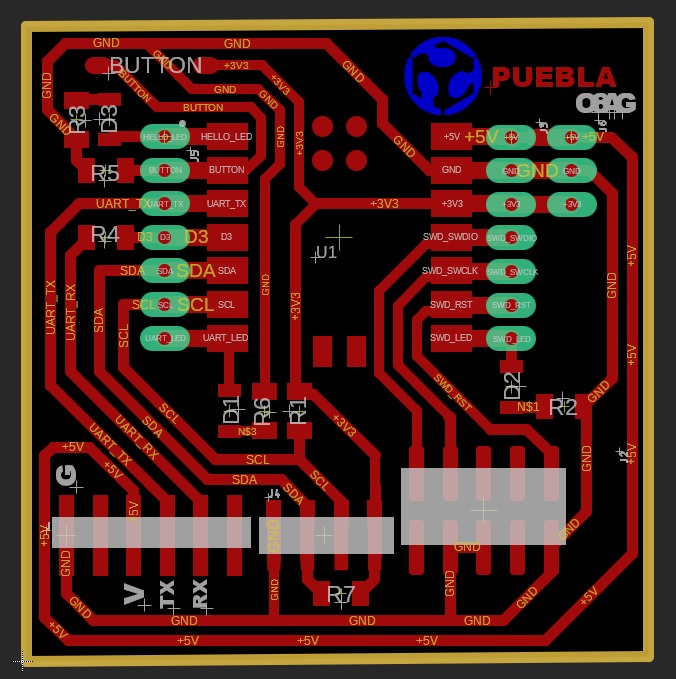
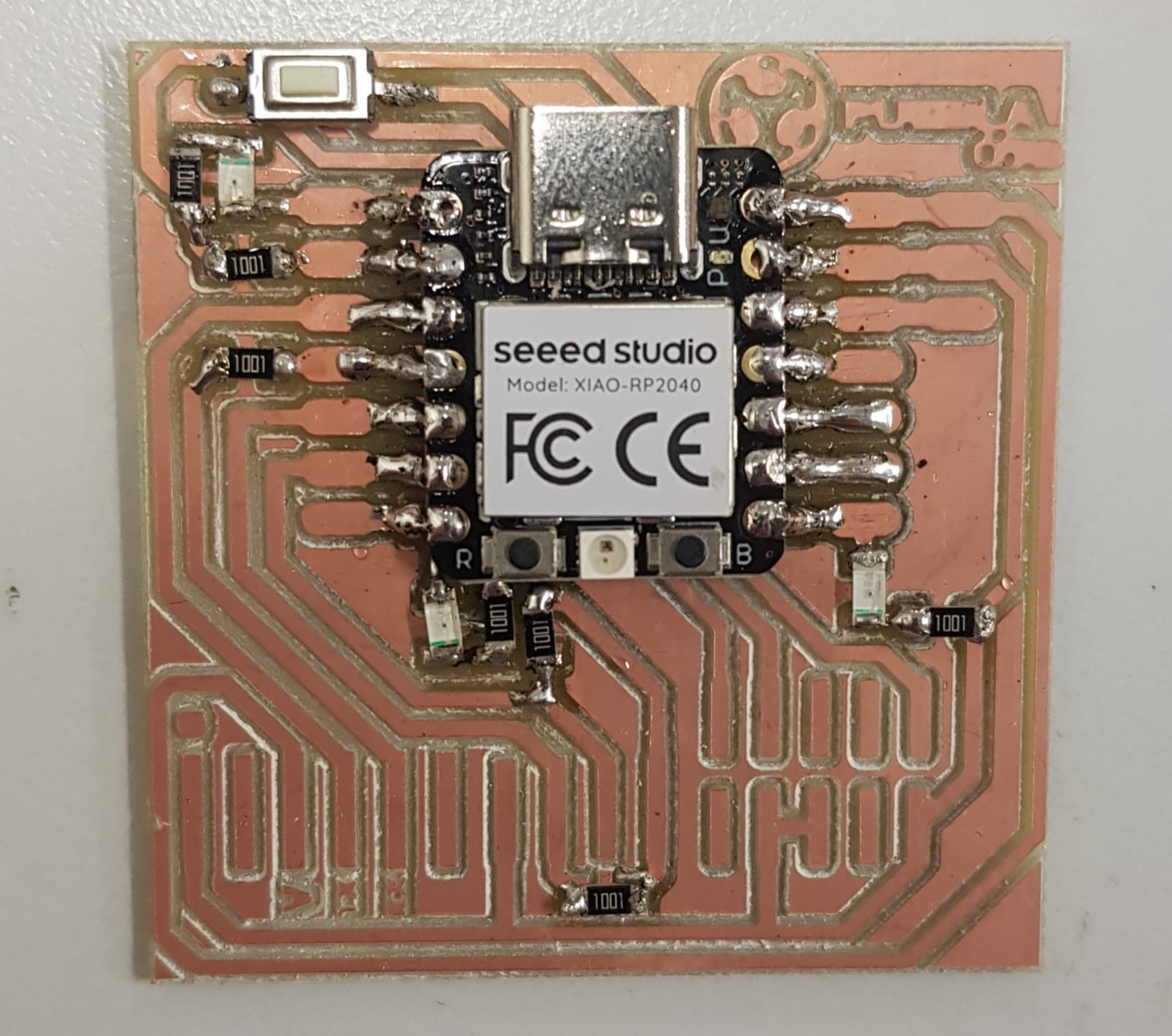
We now detach it from the sacrificial bed and solder it following the next reference image.
These are the components:
7 resistors
3 LEDs
1 button
1 XIADO-RP2040
Board programming
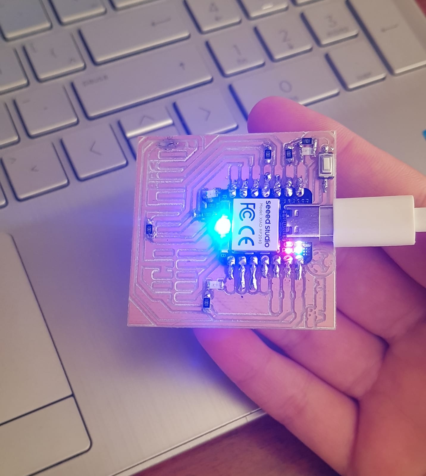
To test if it works, we need to connect it directly to the computer, and some LEDs should light up.
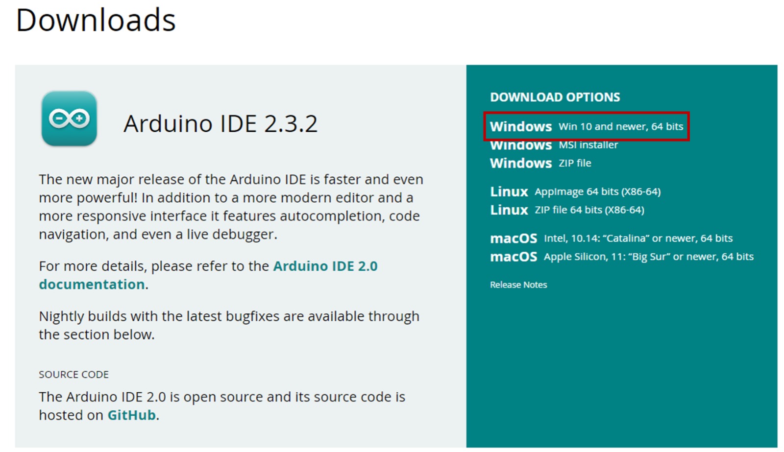
Knowing that the board works, now we need to program it. For this, we must install "Arduino IDE". I selected the
Windows option for my computer.
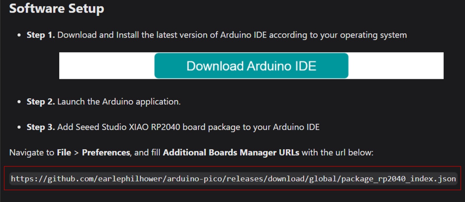
Having the program, now we have to download and install a
"board manager" for the XIAO RP2040. For this, we have to copy the url from the website.
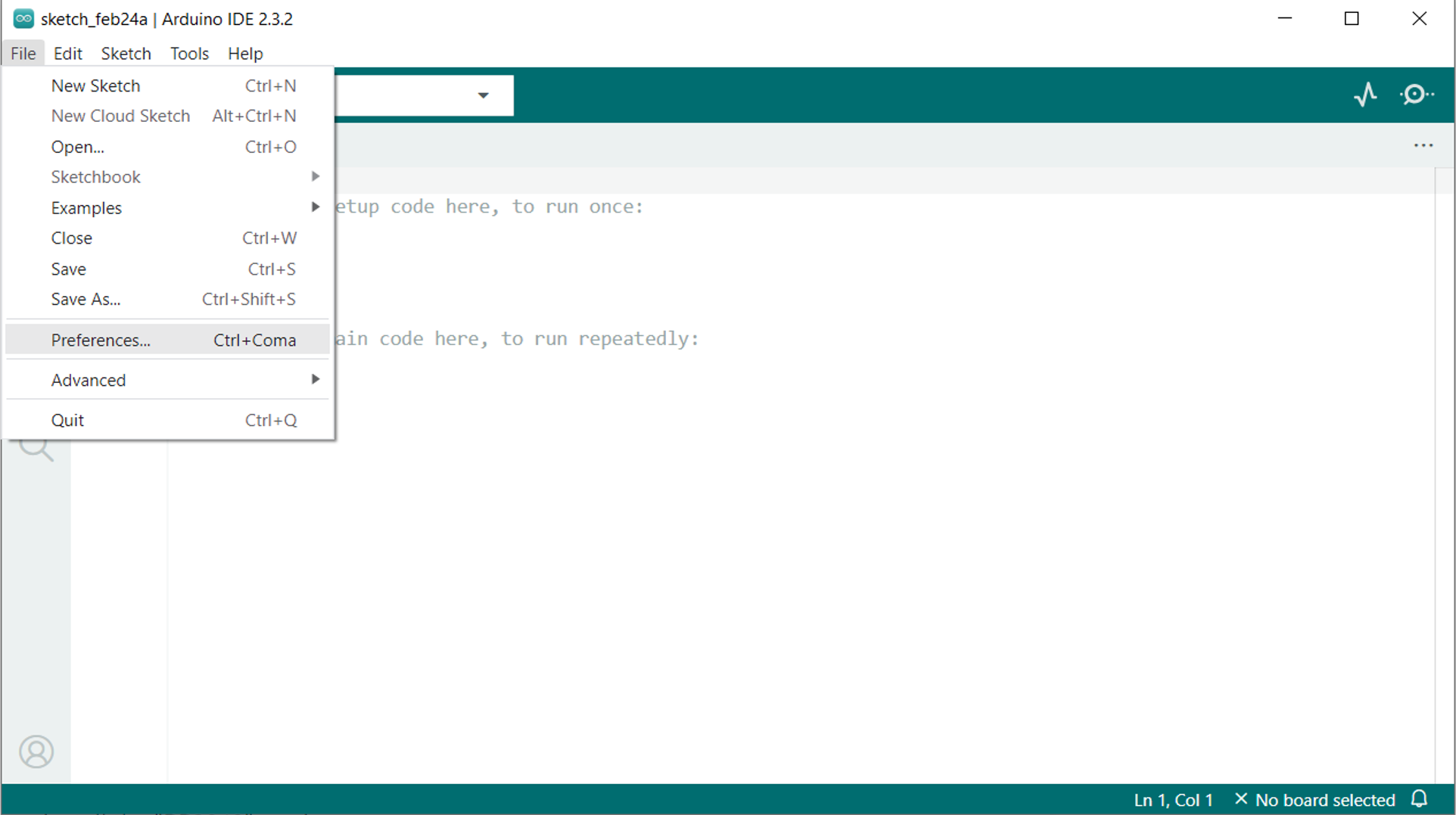
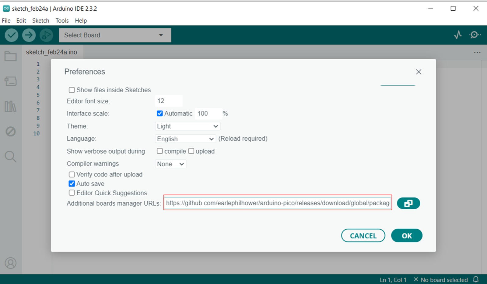
we now have to navigate to File > Preferences, and fill Additional Boards Manager URLs with the url
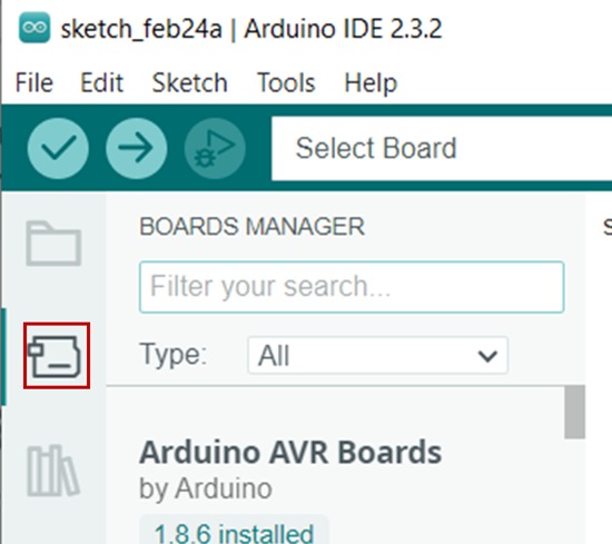
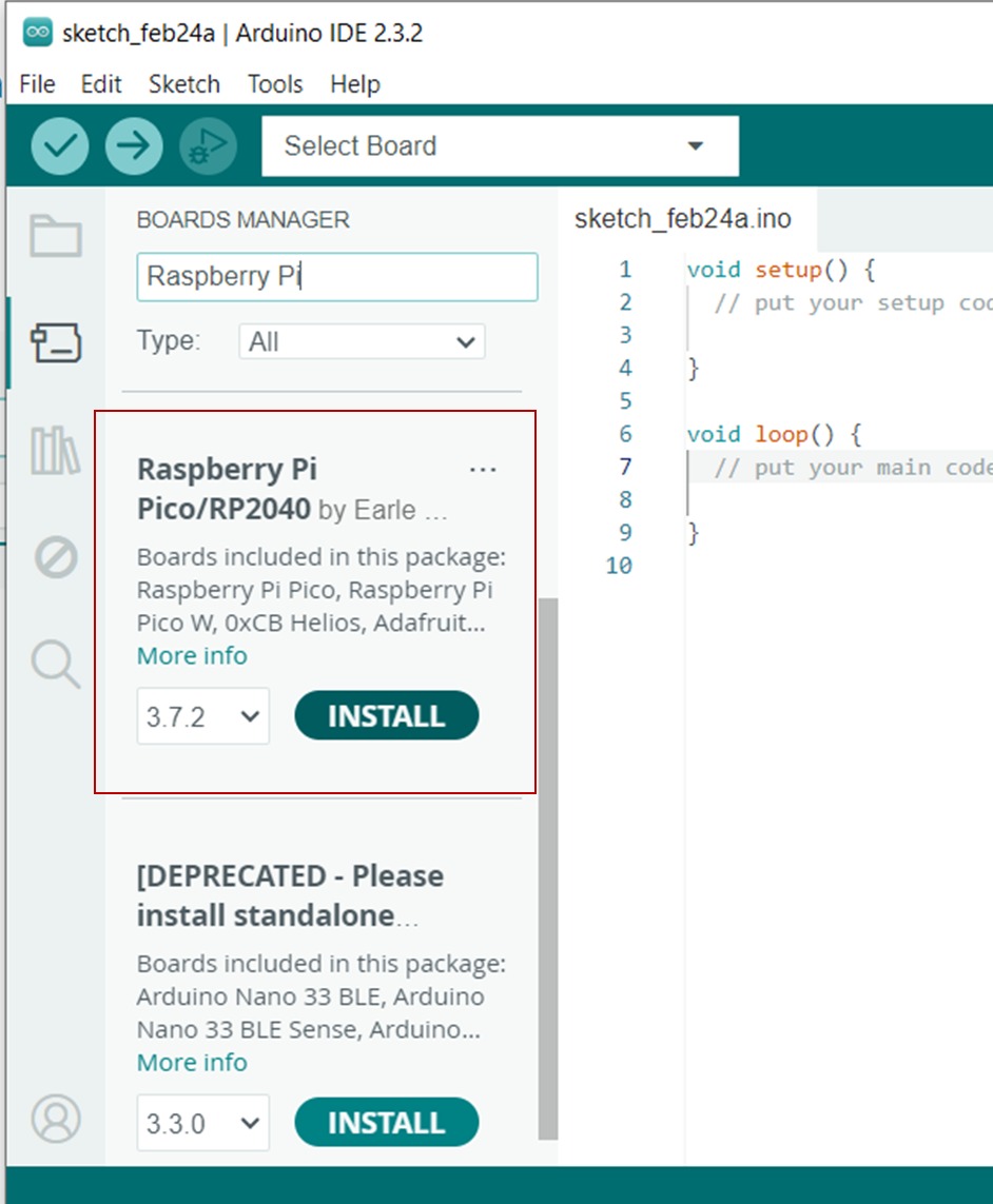
Now we click on "boards manager" and type "Raspberry Pi" in the search bar to install the "RP2040" version.
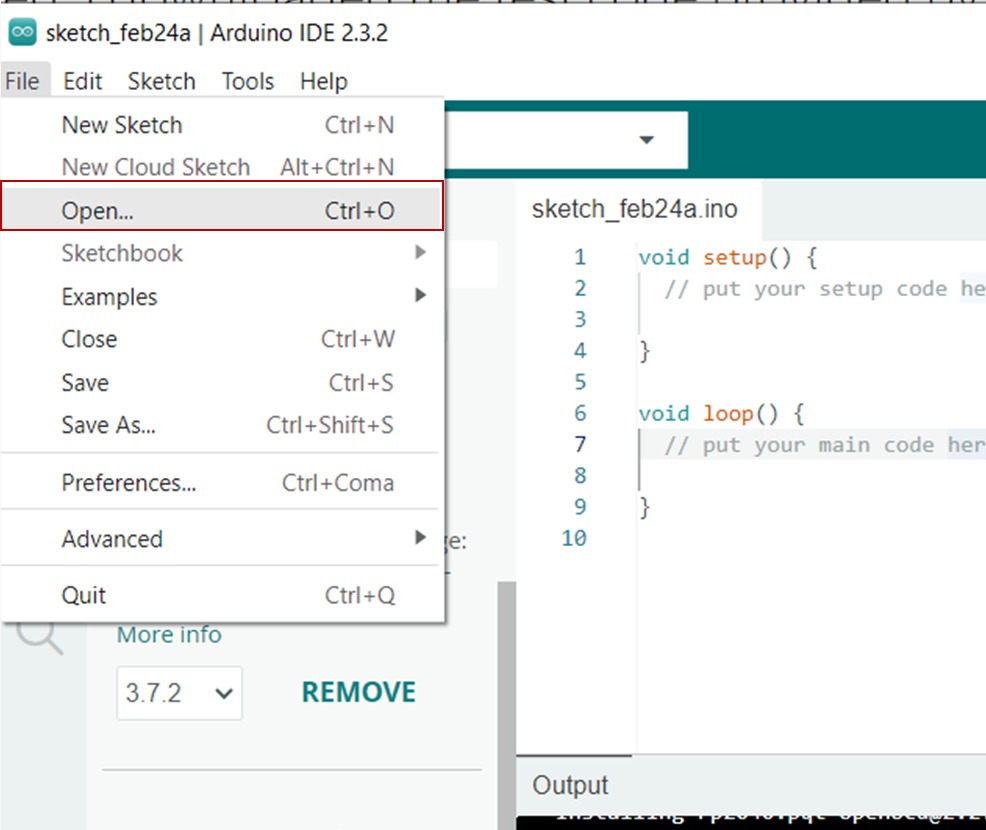
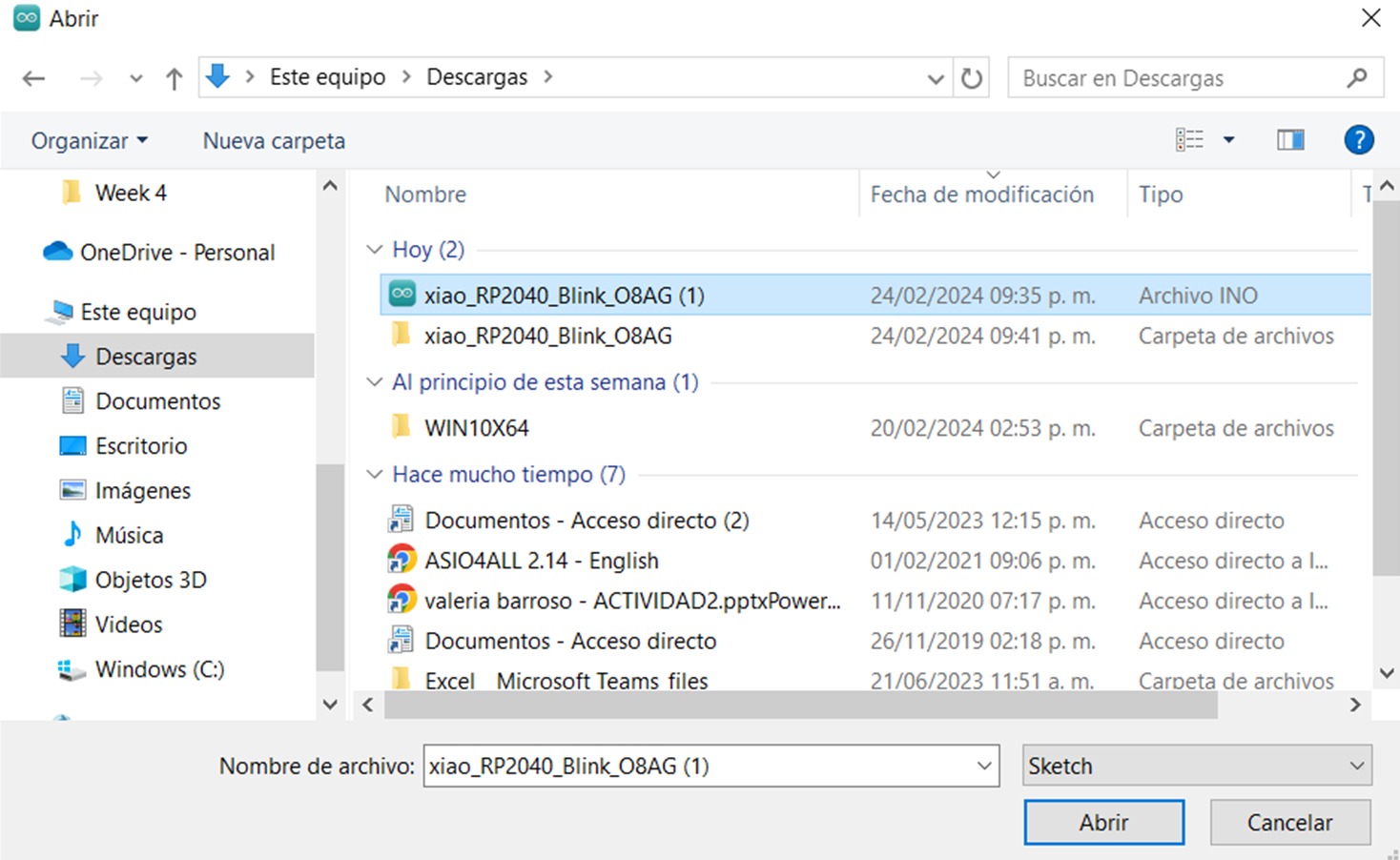
Having it installed, now we go to "file", "open", and select the test code provided to us,
"xiao_RP2040_Blink_08AG".
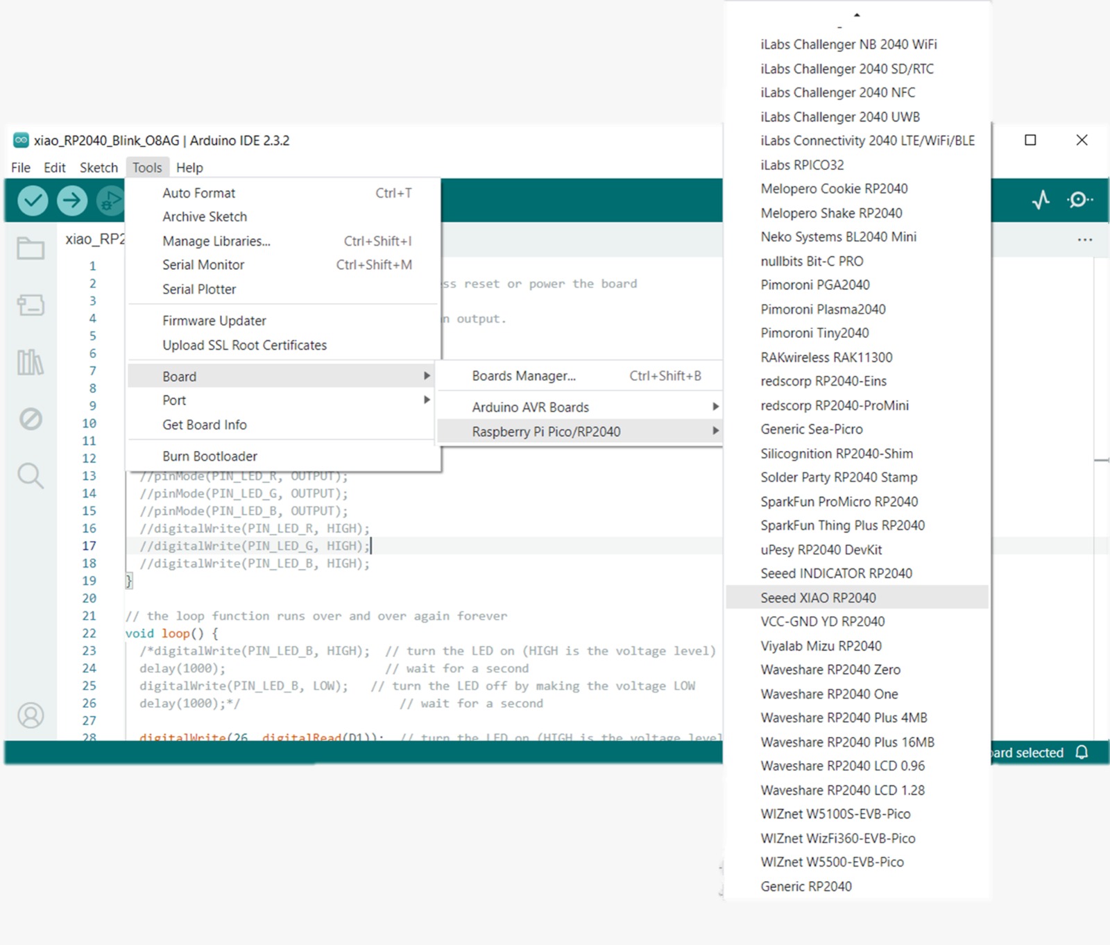
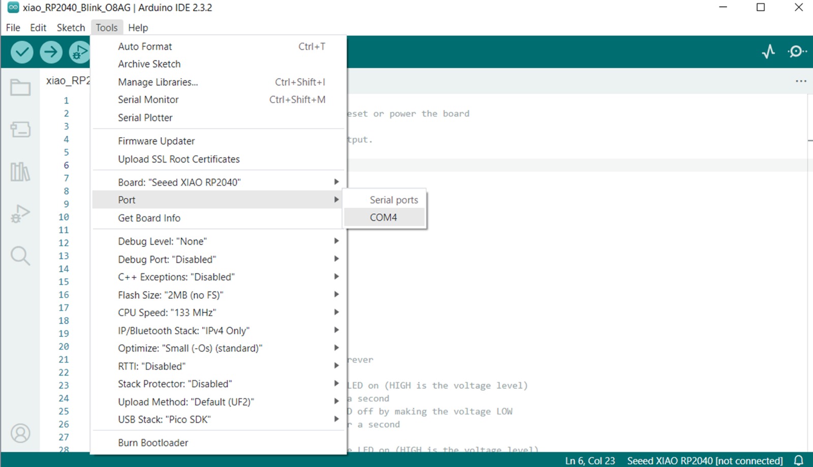
After selecting it, the code should appear, and we can now connect our board. Next, we select "tools",
"board", "Raspberry Pi Pico/RP2040", and "Seeed XIAO RP2040".
Now we select "tools", "port", and "COM4".
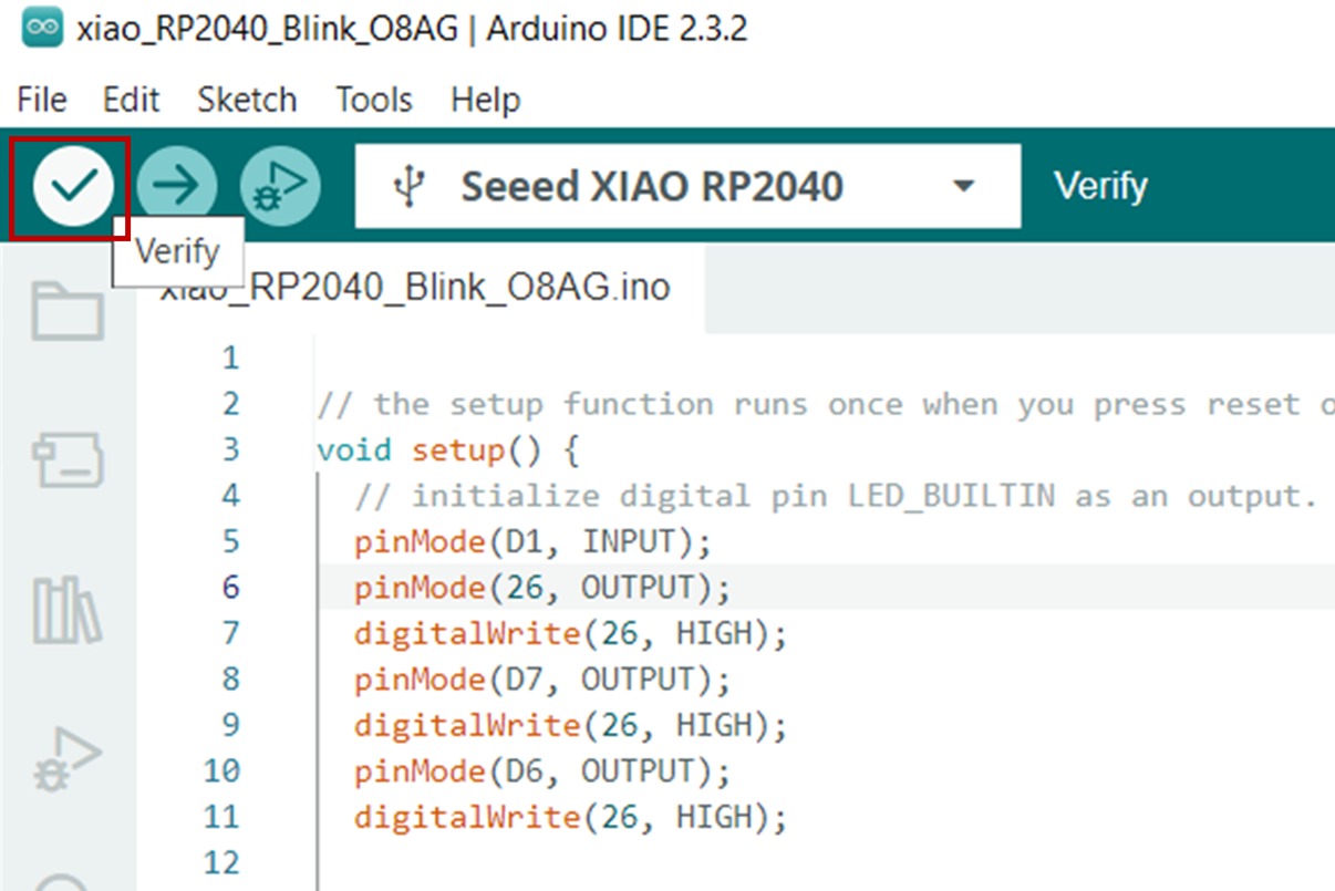
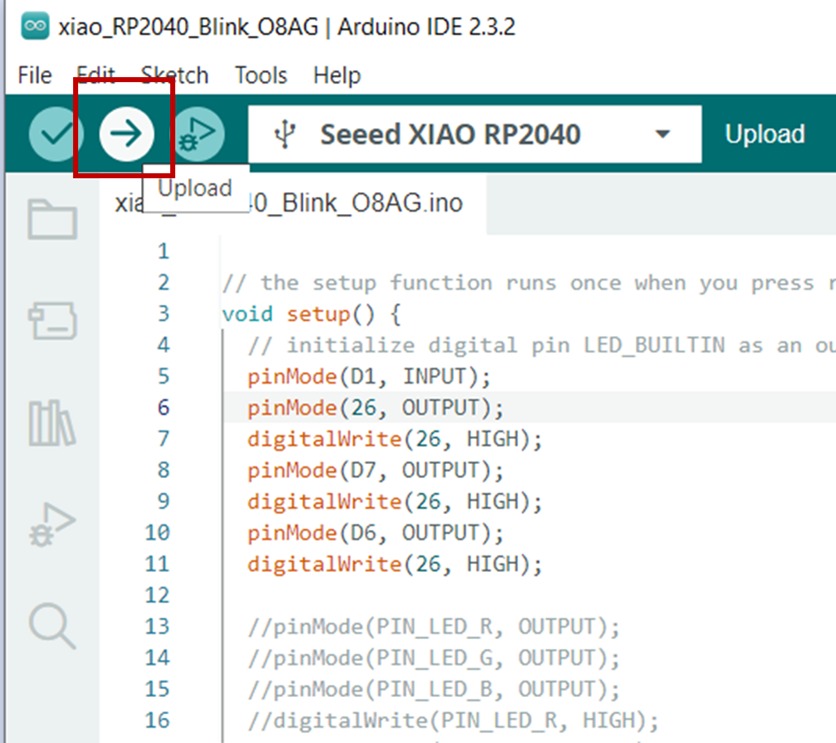
We select "verify" and then "upload".
If everything went well, both lower LEDs should illuminate simultaneously as shown in the following video.
Conclusion:
I was able to finish this week's activity in one day, so it was relatively quick. It gave me
time to improve my website and make some corrections.
