In the group assignment, we characterized the focus, power, speed, rate, kerf, joint clearance, and types of the laser cutter.
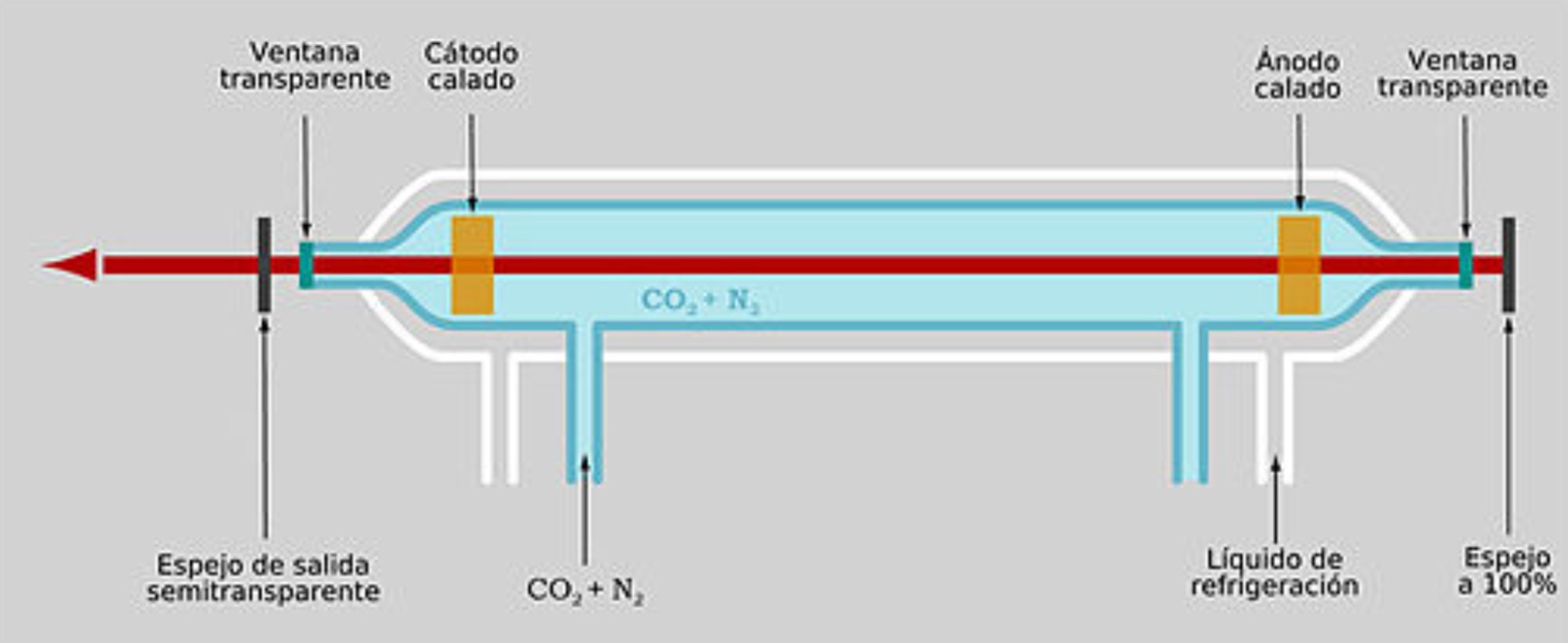
At FabLab Puebla, we have three CAM-five brand laser cutting machines. These create a laser beam by
electrically stimulating a mixture of gases, mainly carbon dioxide in CO2 tubes. The laser passes through
mirrors and a lens to the surface that you want to engrave, cut, or burn.
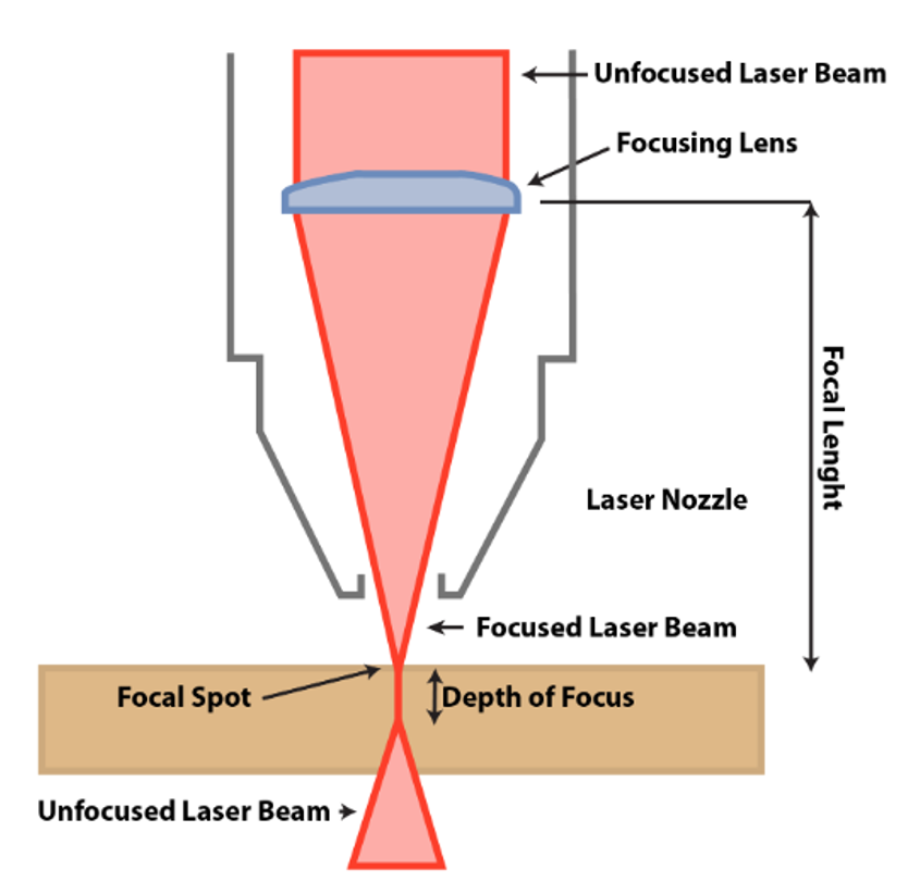
The laser is calibrated as follows
Unfocused Laser Beam: This is the initial laser beam emitted from the laser
source. It is typically wider and less intense than the focused beam.
Focusing Lens: The lens concentrates the laser beam into a smaller, more intense spot.
The quality of the lens and its alignment with the laser source are critical for effective focusing.
Focal Length: This is the distance between the focusing lens and the focal spot. It is a crucial
parameter that determines where the laser beam will be most concentrated. The focal length is
predetermined by the lens' properties and must be calibrated to ensure the focal spot aligns with the
surface of the target material.
Laser Nozzle: This part directs the laser beam onto the material. It is also used to expel any byproducts
from the cutting or engraving process, such as smoke or debris.
Focused Laser Beam: After passing through the focusing lens, the laser beam is now concentrated into a smaller
diameter, which increases its intensity.
Focal Spot: This is the point where the laser beam is most concentrated and, thus, where it will have the
greatest cutting or engraving effect.
Depth of Focus: This parameter represents the range along the laser beam's axis over which the light
remains within a small spot. The focal length and the diameter of the focusing lens both affect the depth of focus.
A longer depth of focus allows for more tolerance in the material's surface height during the process.
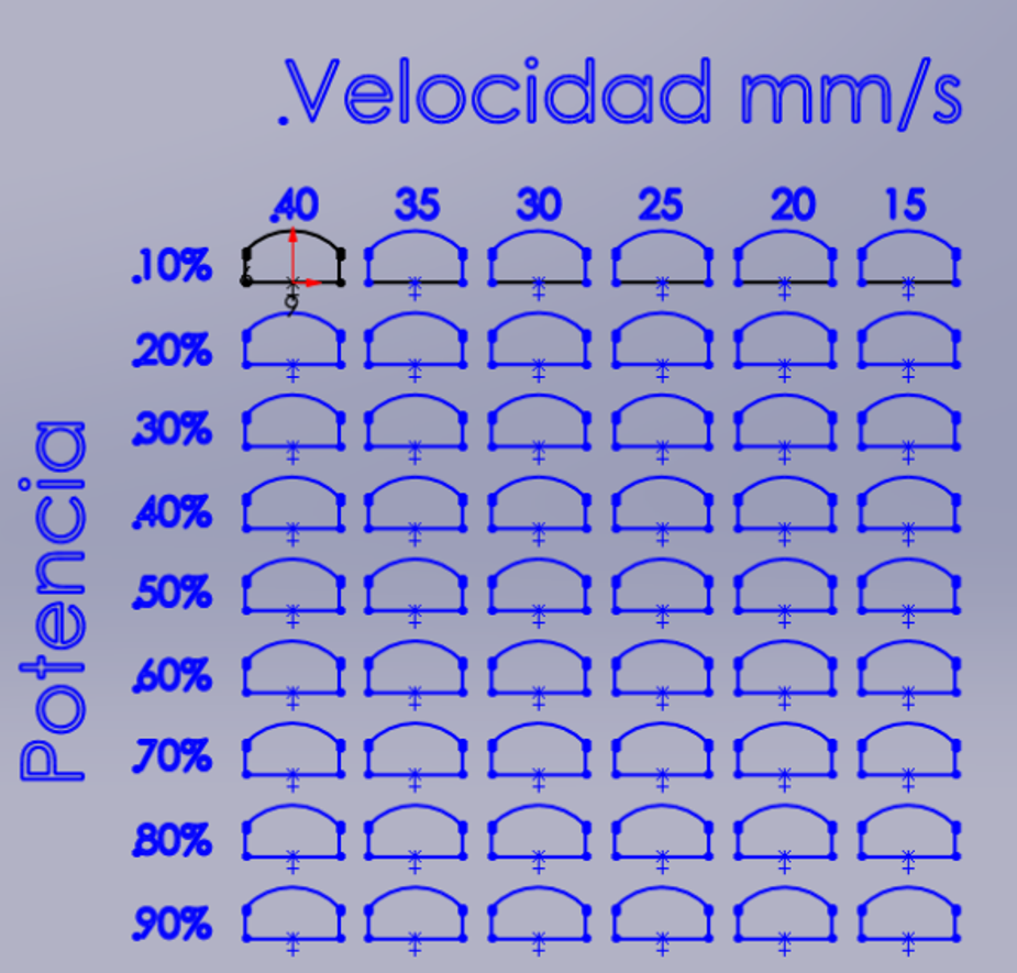
Power and Speed
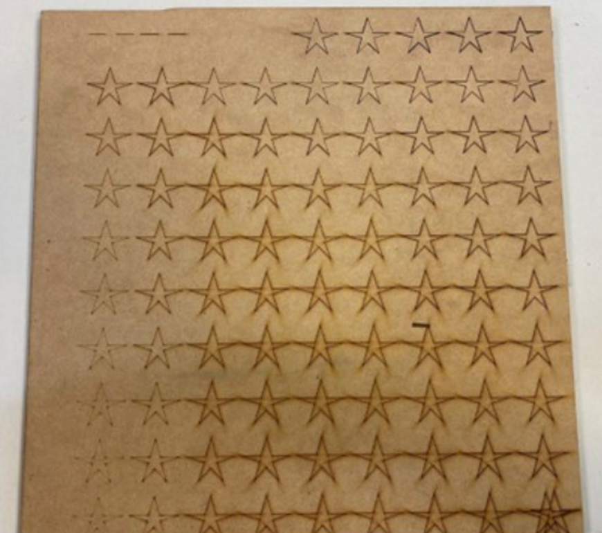
We used two test charts to characterize the laser cutter's power and speed. Starting from a 10% minimum power and
15 mm/s speed, we increased power by 10% increments up to 95% and speed by 5 mm/s increments up to 40 mm/s.
This method helped identify optimal settings for different materials.
Power percentages below 30% were ineffective for cutting, and 10% couldn't even engrave the material.
At 40% power, the laser barely cut through, requiring the slowest speed for a proper cut. The cleanest cut was achieved
at 50% power and 40 mm/s speed. Slower speeds led to excessive burning and wider kerfs.
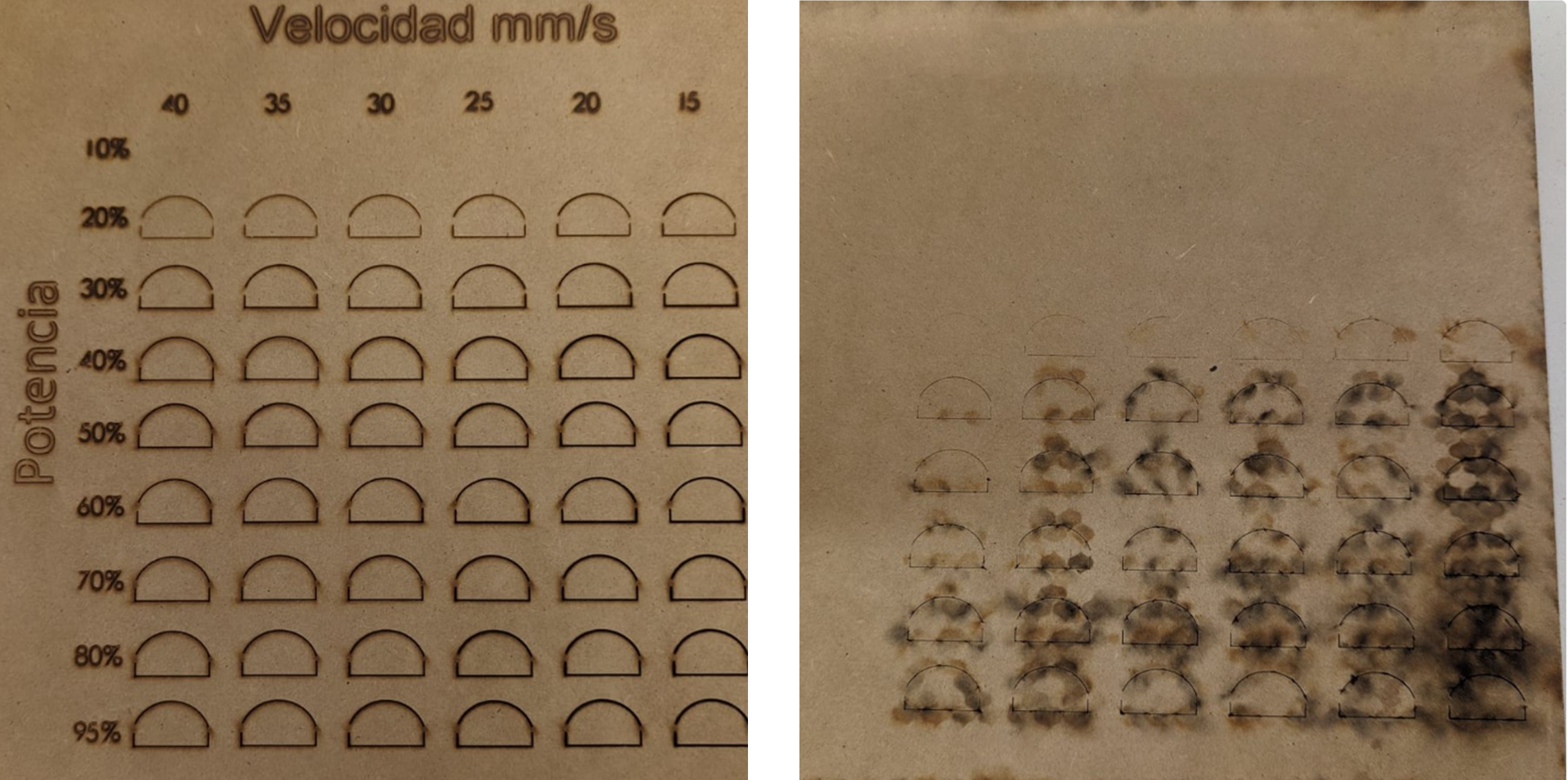
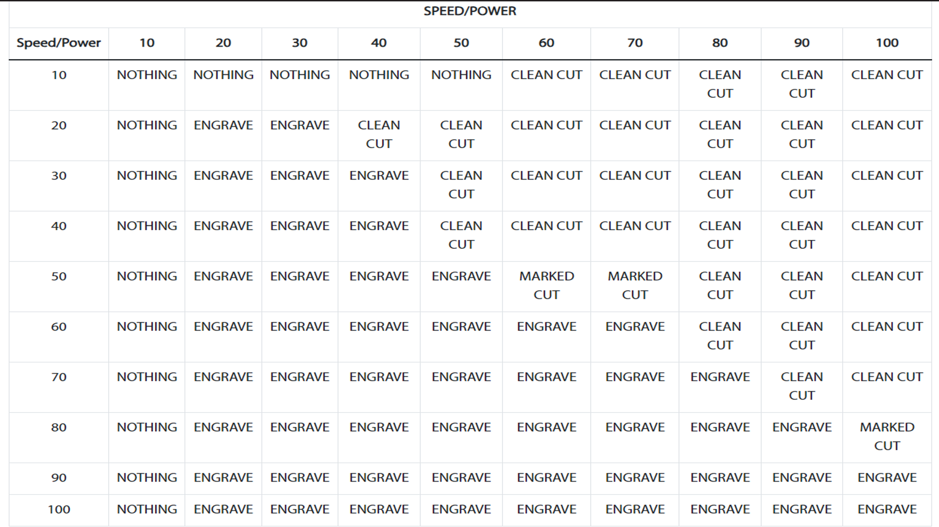
The second test is more detailed making the matrix bigger, to test more speeds,
still having an increase of 10% power but adding speeds every 10 mm/s up to 100 mm/s.
The second set of results, detailed in a table due to their complexity, faced an issue with the number of combinations and layers,
resulting in the loss of the first line where speed ranged from 10 mm/s and power from 10% to 50%. Nonetheless,
we observed a clear linear pattern between engraving and cutting. There's a correlation where lower power is required for cutting,
whereas higher speeds demand more power. This relationship is clearly delineated in the data.
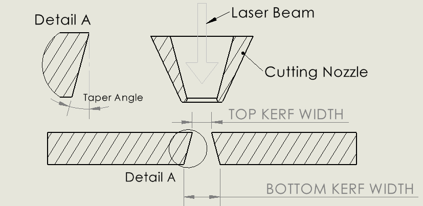
Kerf
When a laser cutter cuts a line, it burns away material. Because a laser beam has a certain width, you end up with a part
that is slightly smaller than you want, unless you account for this. The kerf of a laser is the amount of material that gets burned away
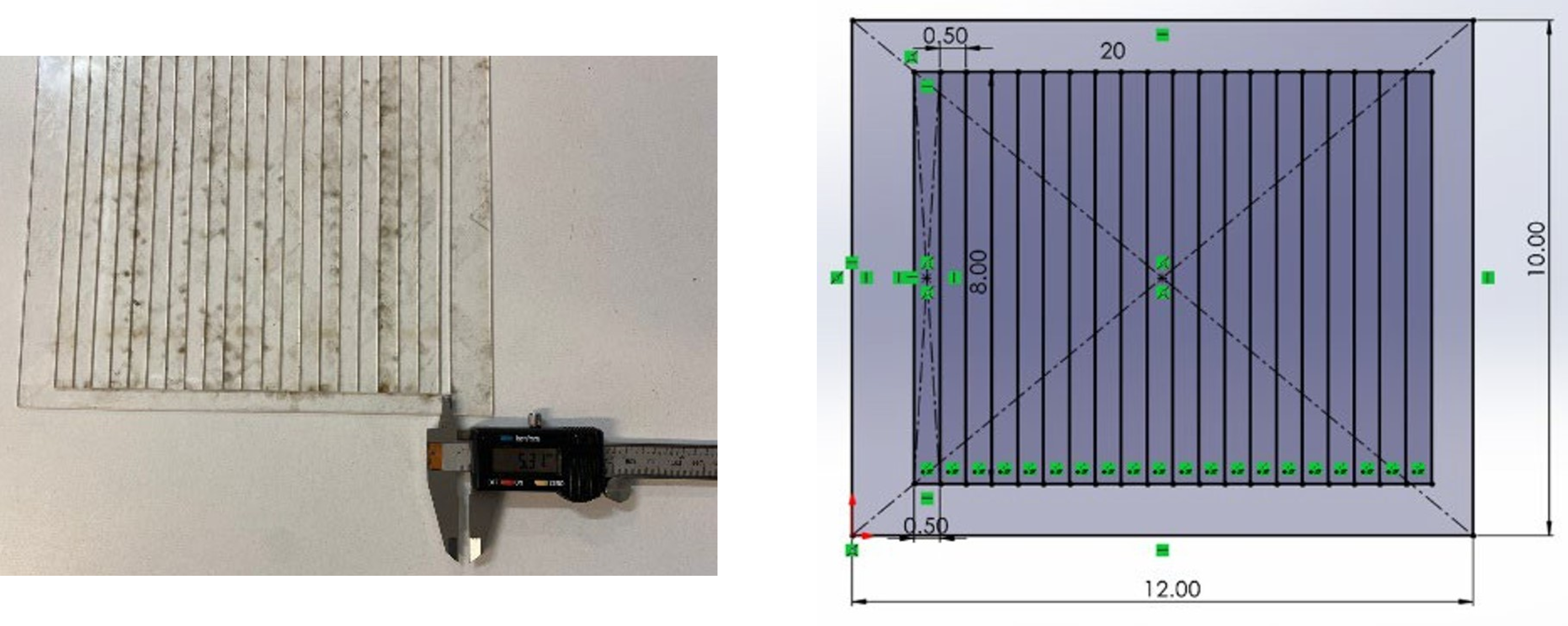
MDF
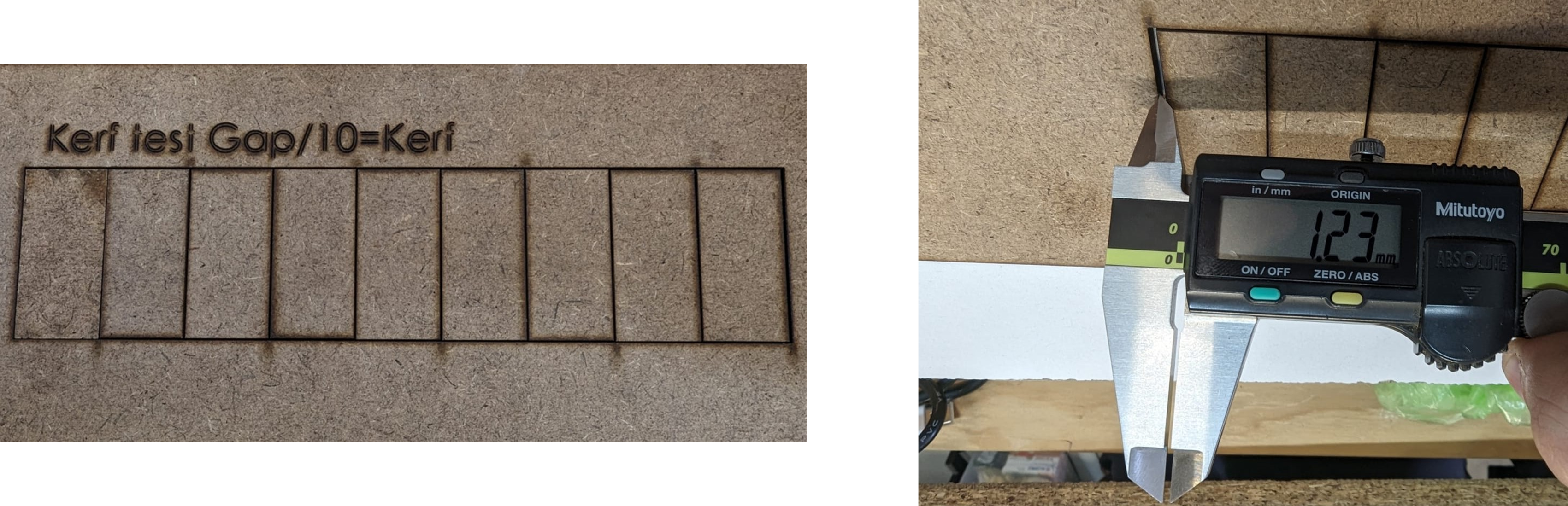
To determine this, we created a set of rectangular pieces and tested them using both 3mm MDF and 3mm acrylic.
By counting the number of lines, we established a formula where each inner line represents a full kerf. By shifting all
pieces to one side, we created a measurable gap using a caliper. This allowed us to calculate the kerf by dividing the
gap by the number of cuts.
MDF 3mm 10 cuts Speed 40 mm/s Power 50%
1.23 mm/10 = .123 mm kerf
Acrylic
Acrylic 3mm 21 cuts Speed 40 mm/s Power 50%
5.31 mm/21 = .252 mm kerf
Joints
One of the most common applications of laser cutting is the creation of joints for
assembling parts without the need for additional hardware like screws or glue. These are known as laser cut joints.
Types of joints:
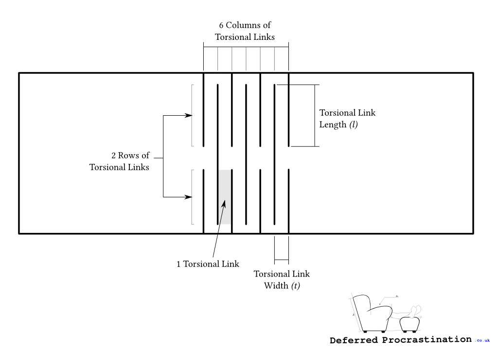
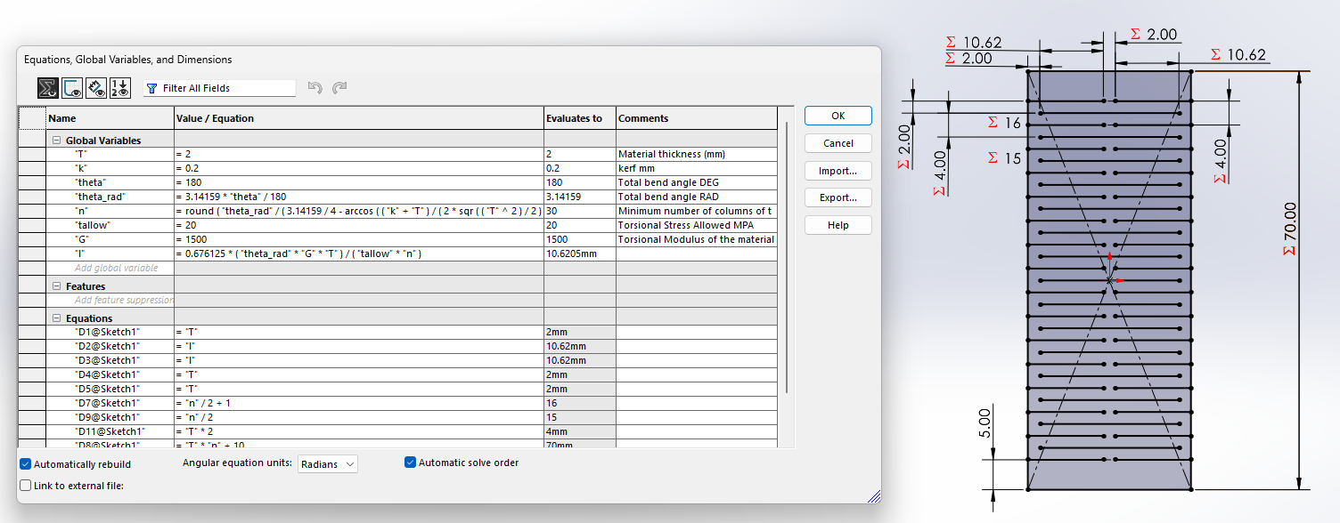
Also, flexible pieces can be made. For example, in
Deferred Procrastination
, they calculated a way to achieve a
parametric design of a "living hinge".
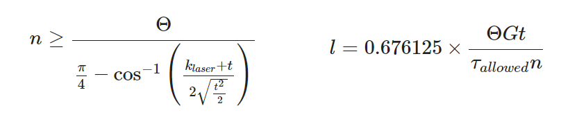
This is achieved with the following equation.
Nomenclature
Θ = Total bending angle of the piece (Θ=θ×n)
k laser = Laser cutting (m)
l = Length of torsional link (m)
n = Number of torsional link columns
t = Material thickness (m)
G = Torsion modulus of the material (Pa)
τ = Torque (Pa)
From this formulas we obtained the following design made in Solidworks which you can download
HERE.
The main parameters to change is the width of the material, the laser kerf and finally the bend angle that's needed.
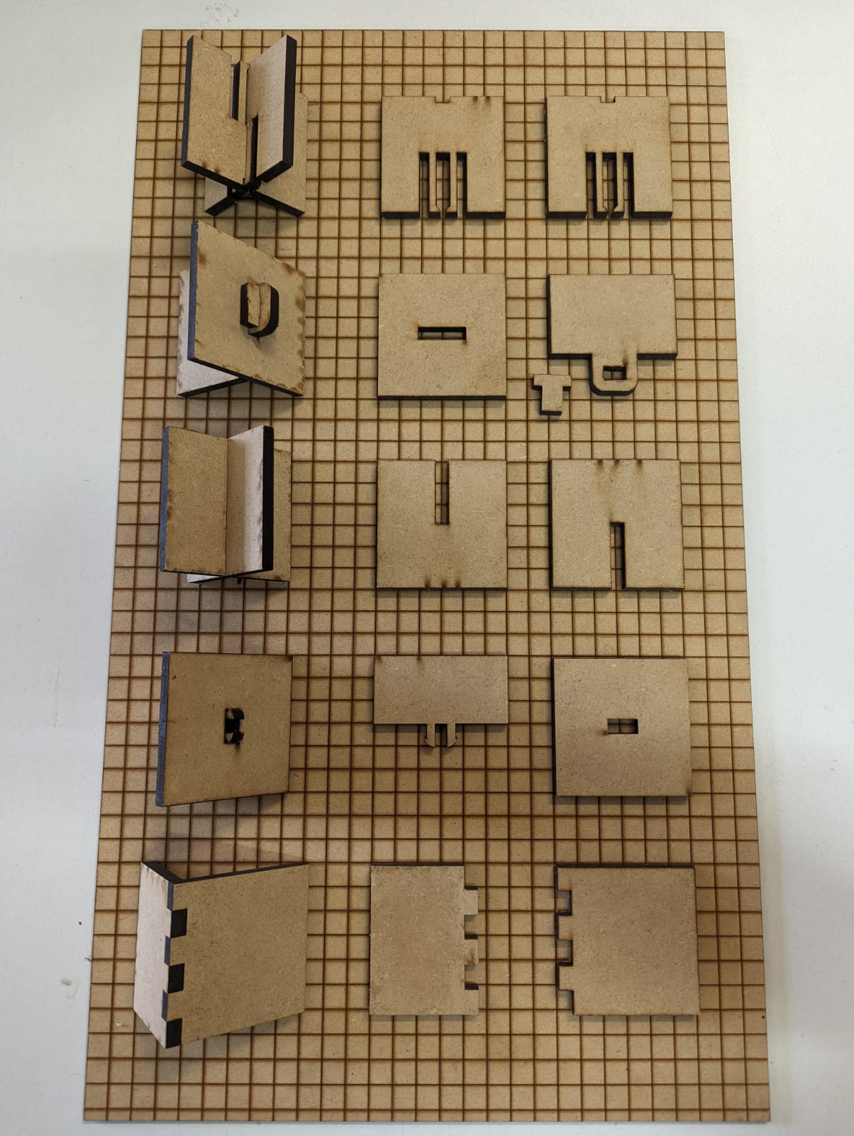
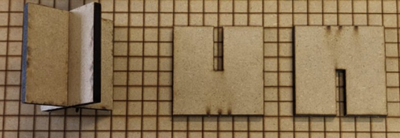
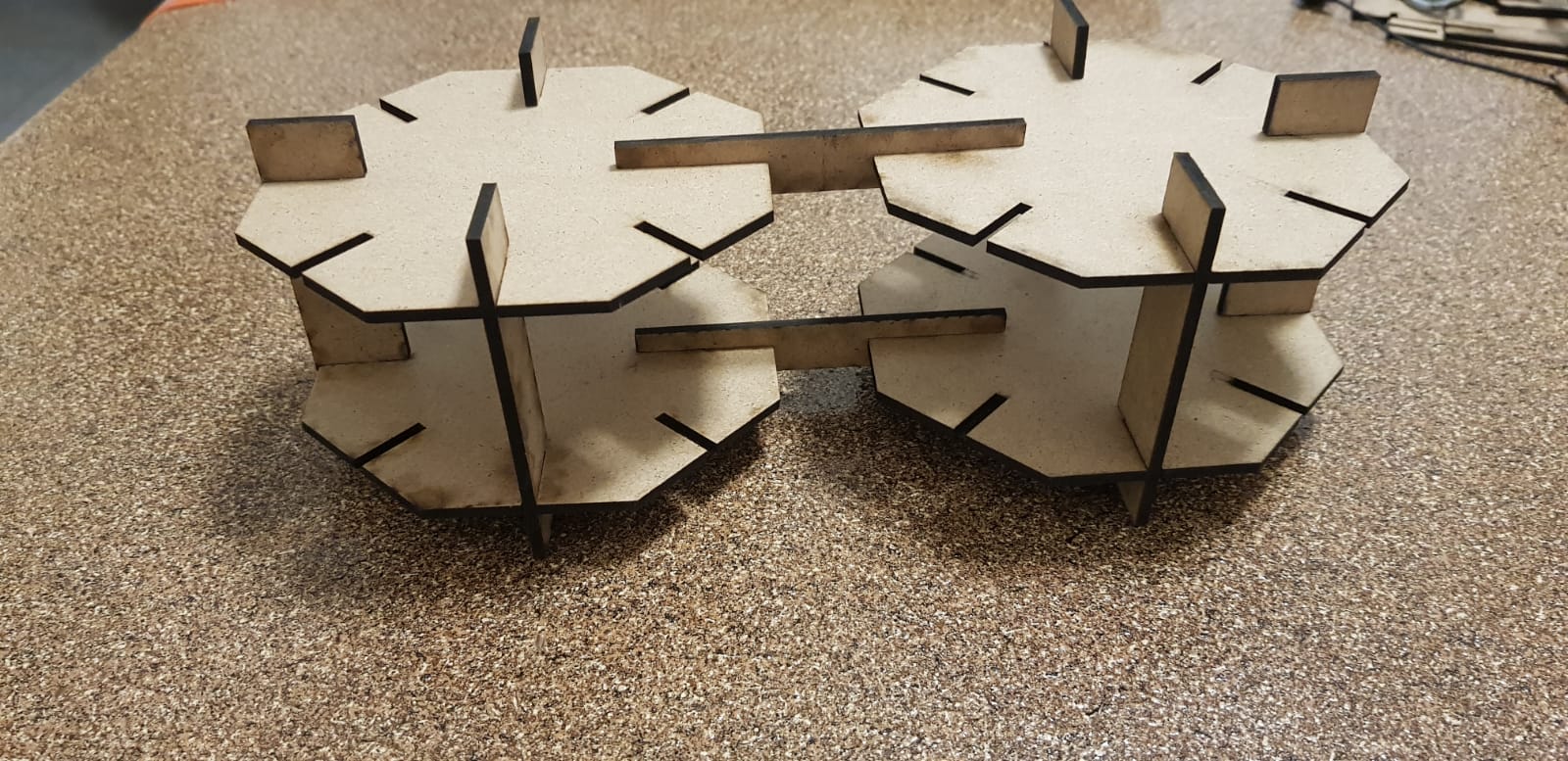
For the first individual assignment, we need to design, laser-cut, and document a parametric construction kit,
accounting for the laser cutter's kerf, which can be assembled in multiple ways.
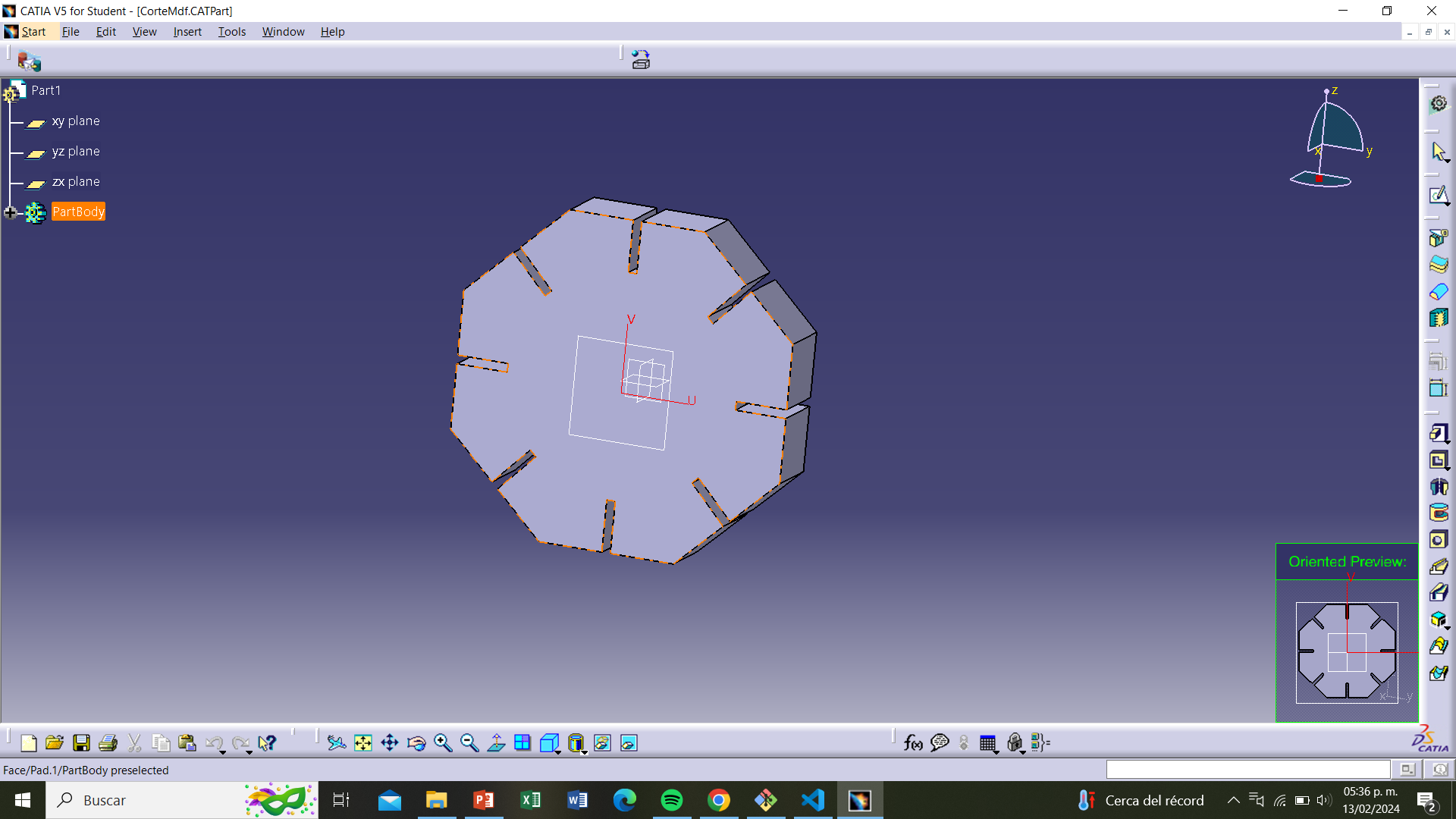
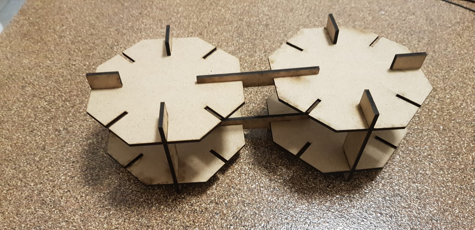
I designed and cut three parts, the first one is an octagon, the second one is a vertical joint, and the third one is a horizontal joint.
Step 1
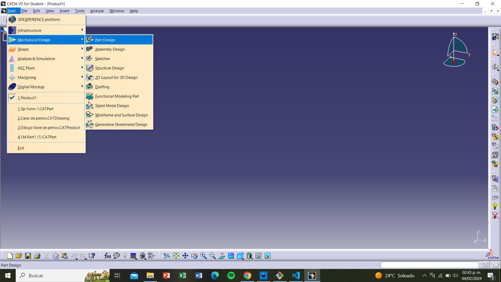
In Catia V5, starting from the main panel, we select start, mechanical design, and then part design.
Step 2
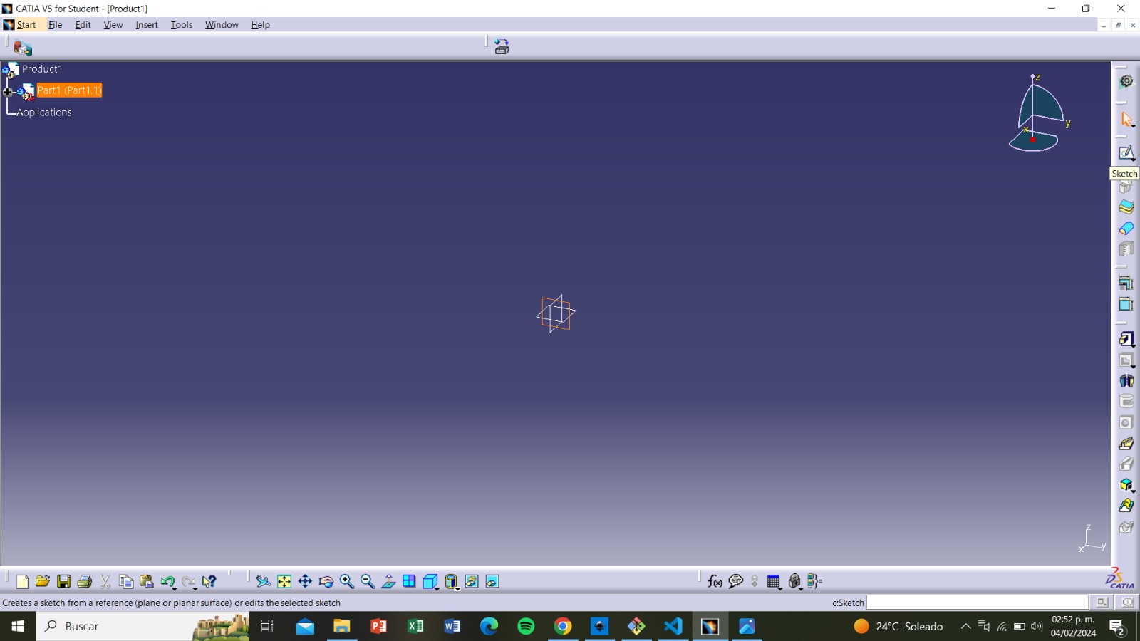
We select a view and then click on sketch.
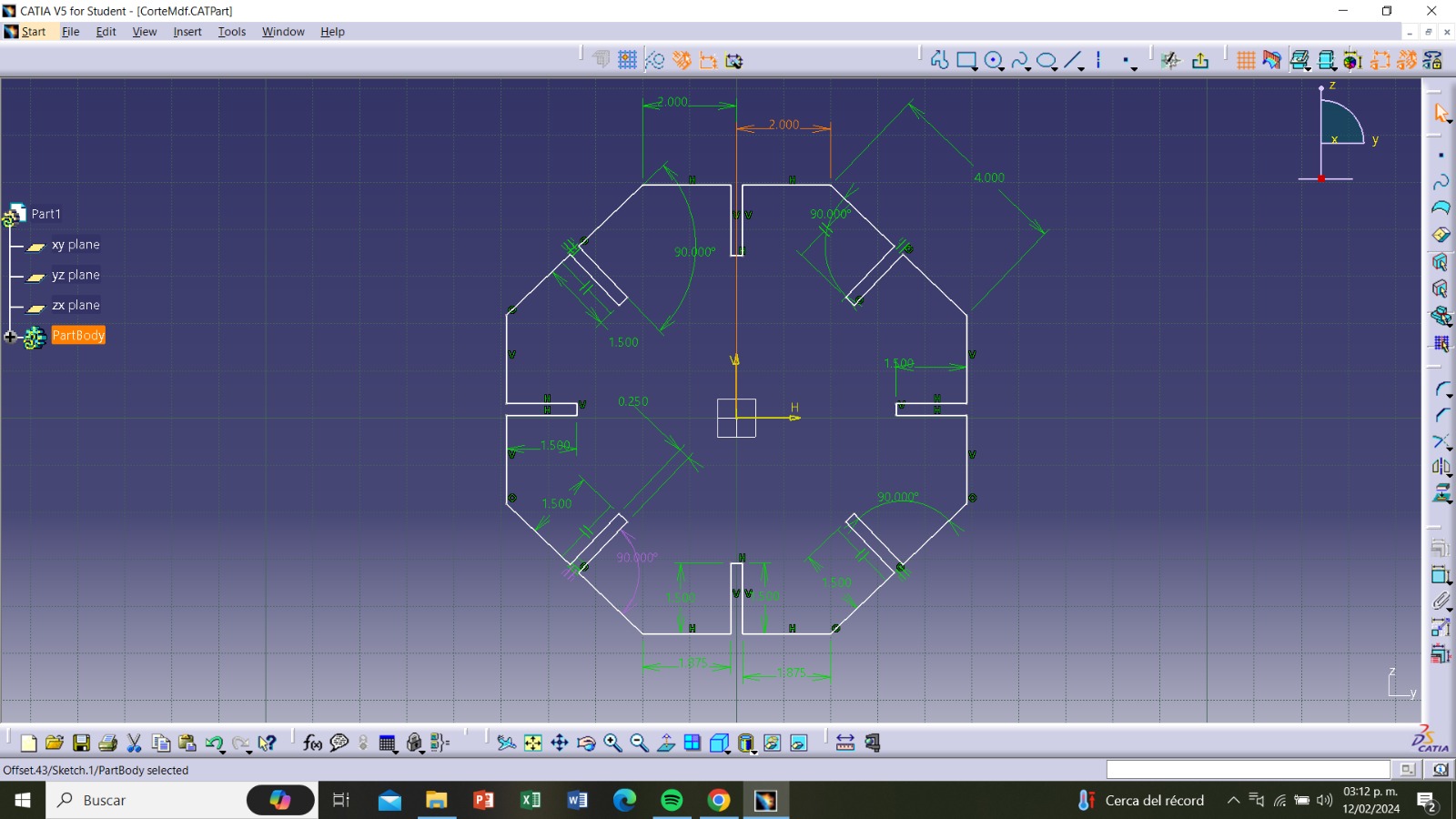
Step 3
We can start drawing from the opened window. I decided to make it an octagonal shape so that it has several
spaces where it can be connected. I began by drawing the sides and then the holes where they would
assemble with the other pieces. I decided they should connect like the third example in the image of types of
joints shown in the group assignment.
Step 4
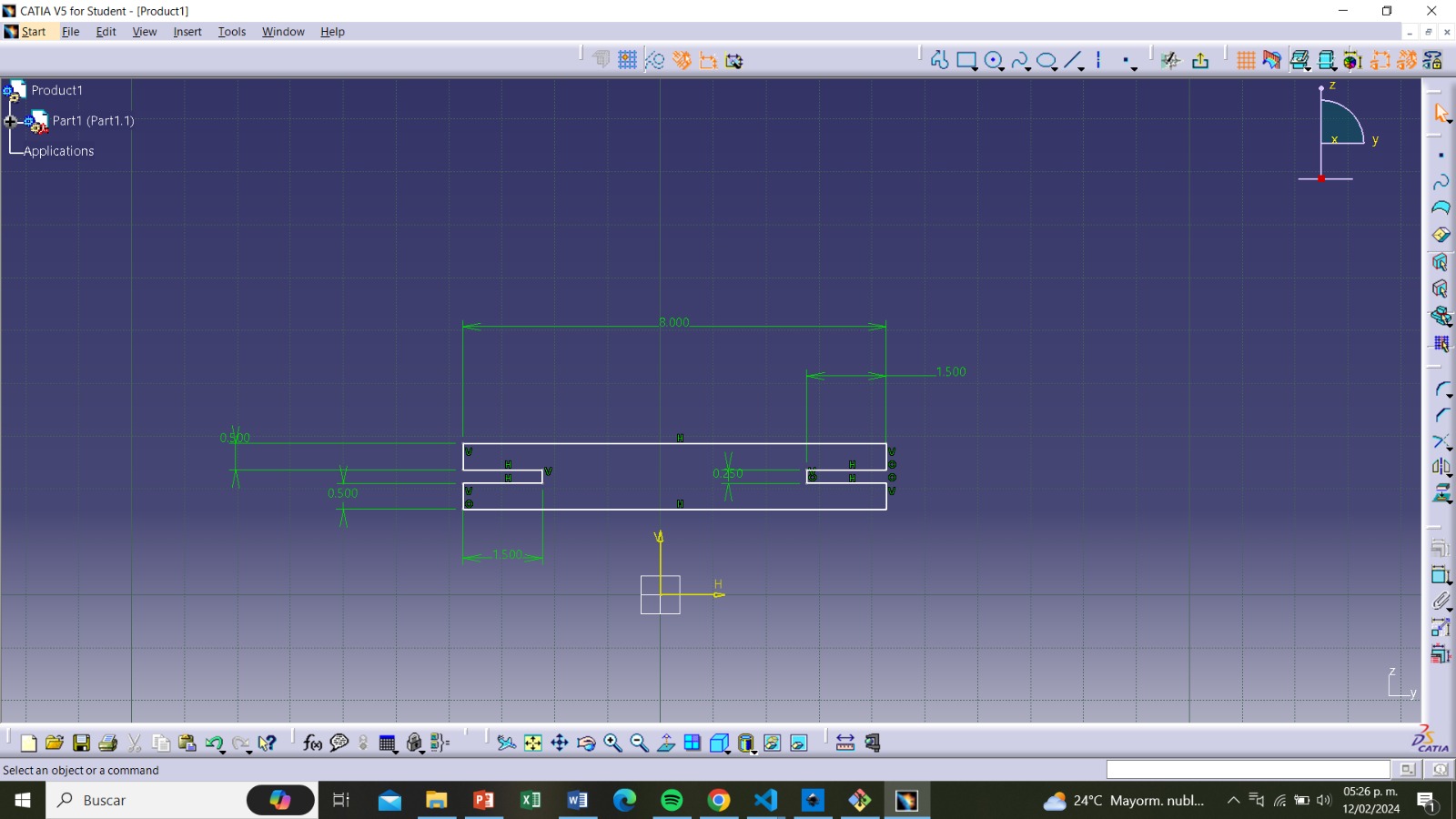
The measurements are as follows:
Height: 9.7cm
Width: 9.7cm
Width of each side: 4cm
Hole width: 0.25cm
Hole width with kerf: (0.25cm-0.0252cm)= 0.2248cm
Hole length: 1.5cm
This is what it looks like once all of the sides have the holes with the right measurements.
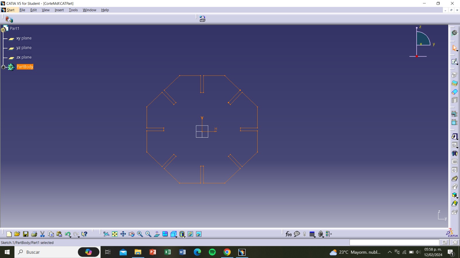
Step 6
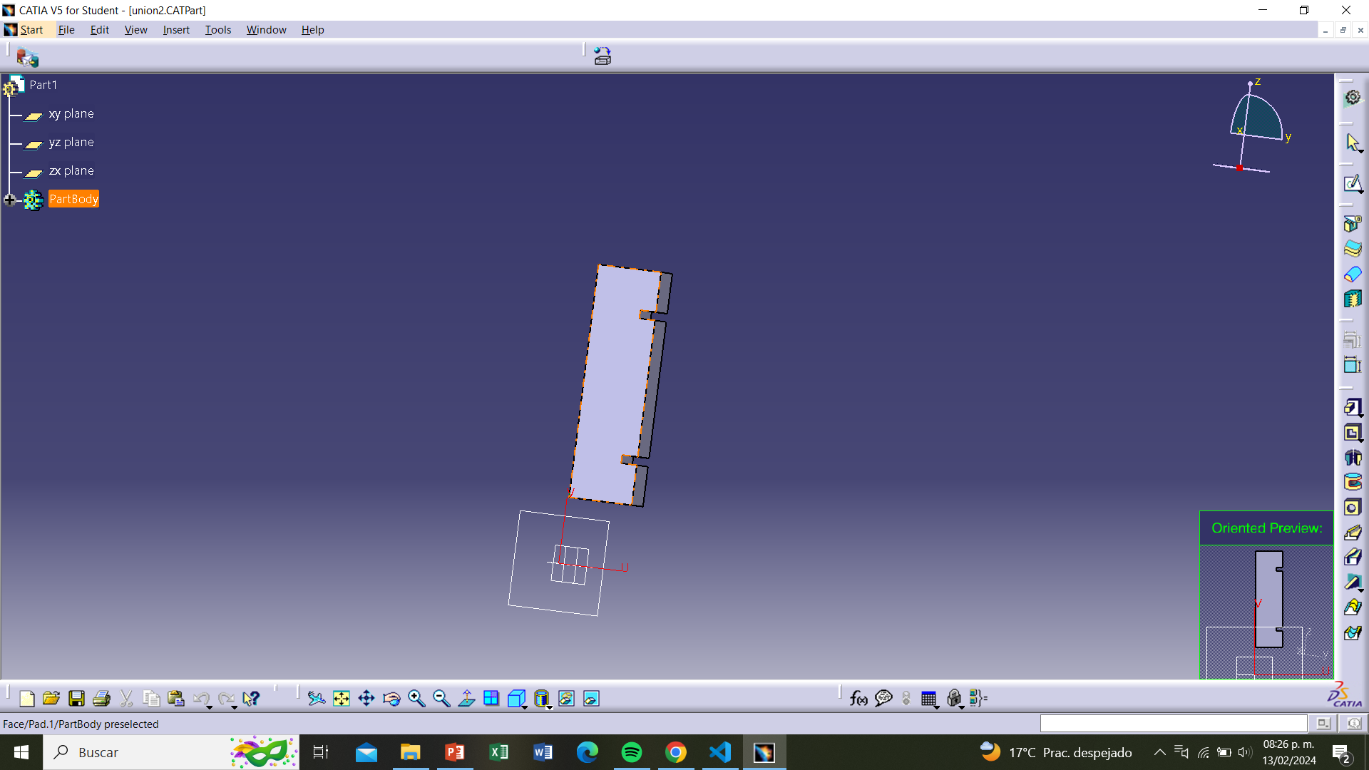
We now click on "exit workbench", which takes us out of the drawing and shows us how our part looks like.
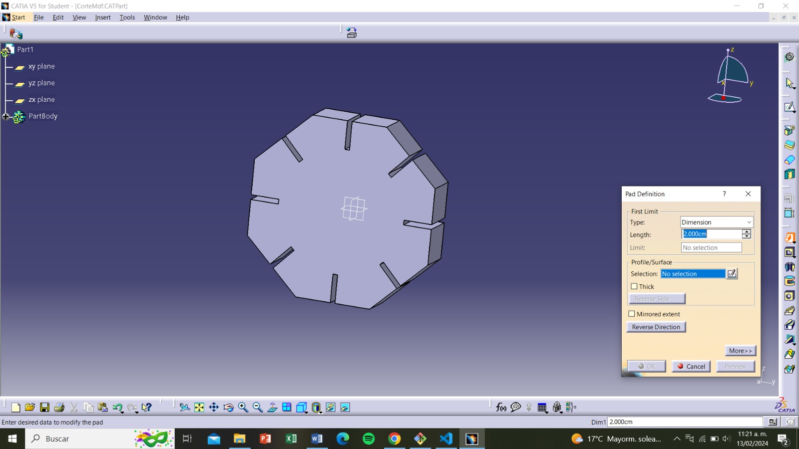
Step 7
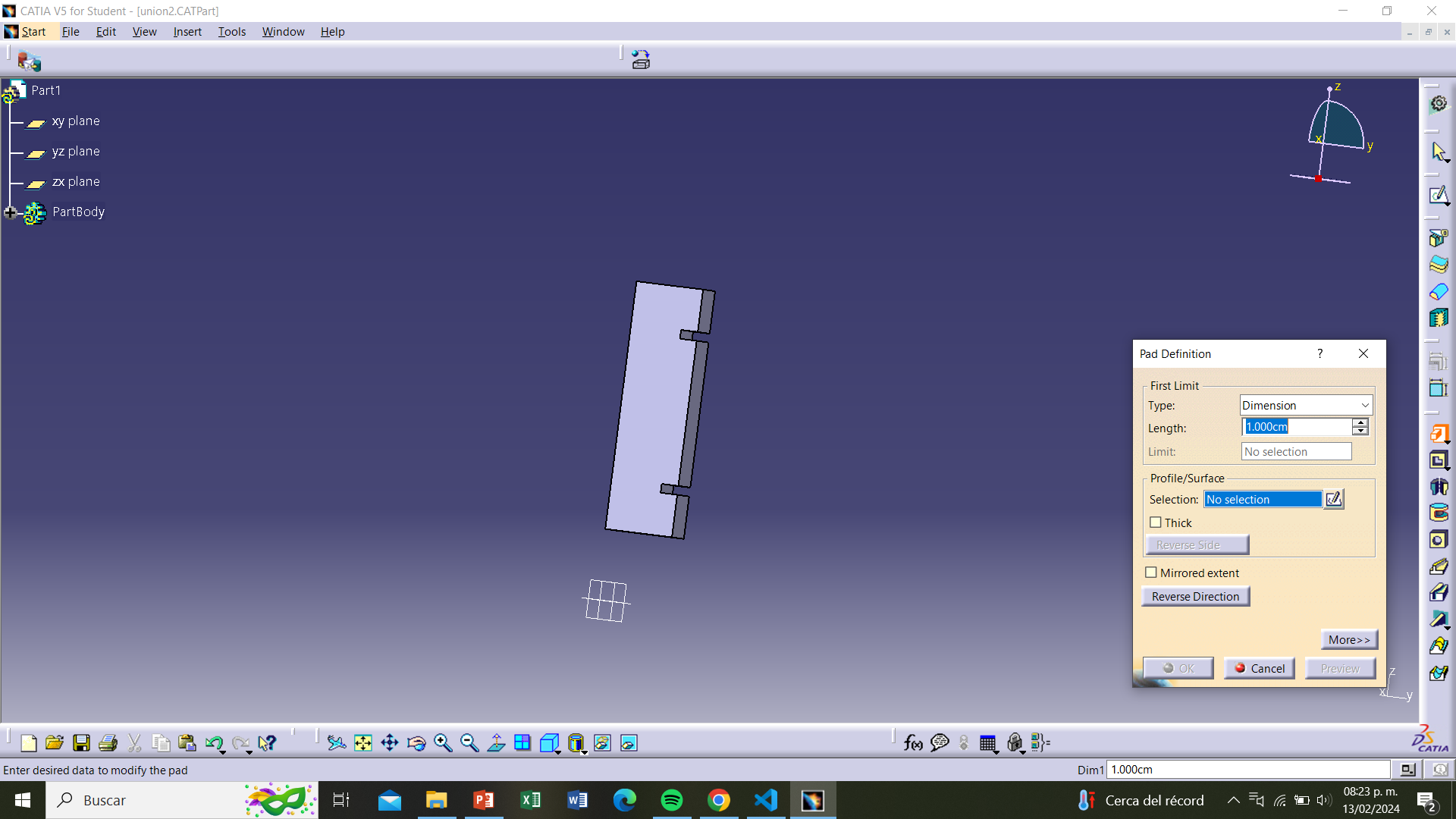
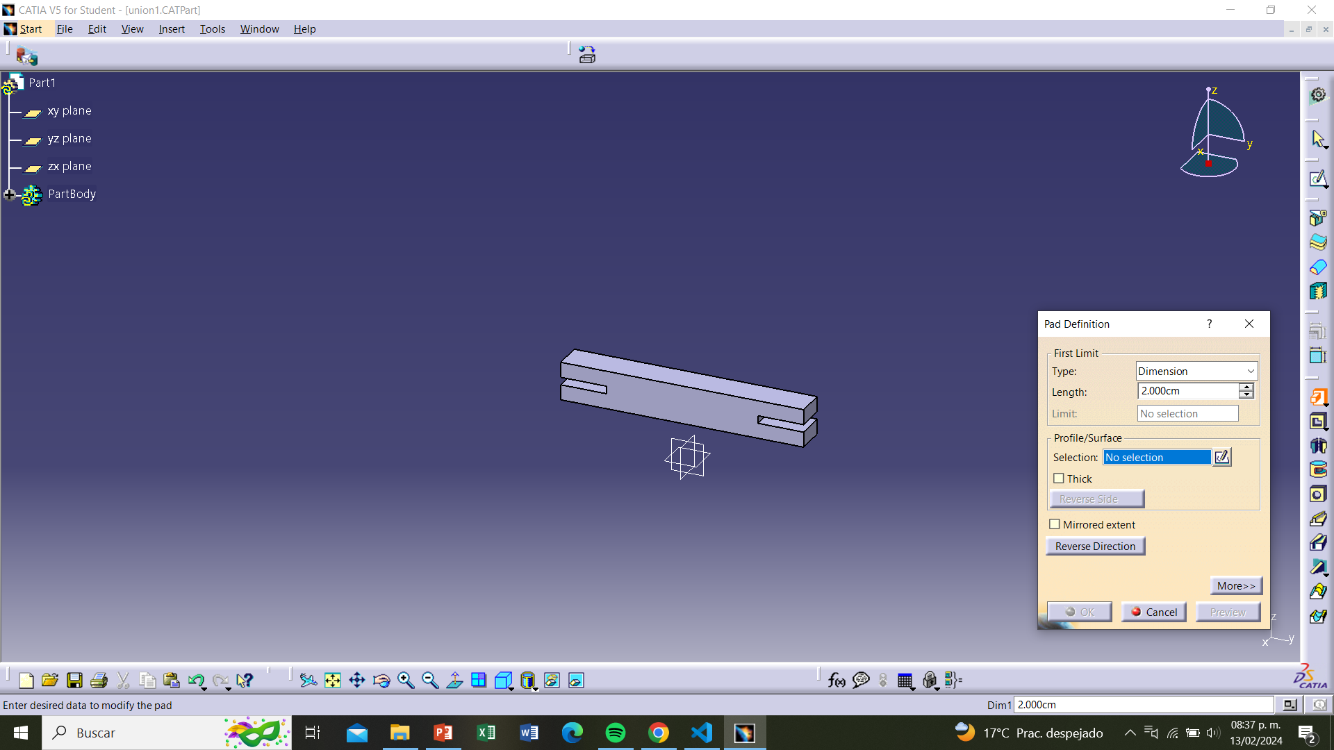
To cut the MDF piece, we need to convert the file to DXF format. To do this, we click on "pad definition"
and select any measurement in "length", I chose 2 cm. Then, we click on "preview" and then "ok".
Step 8
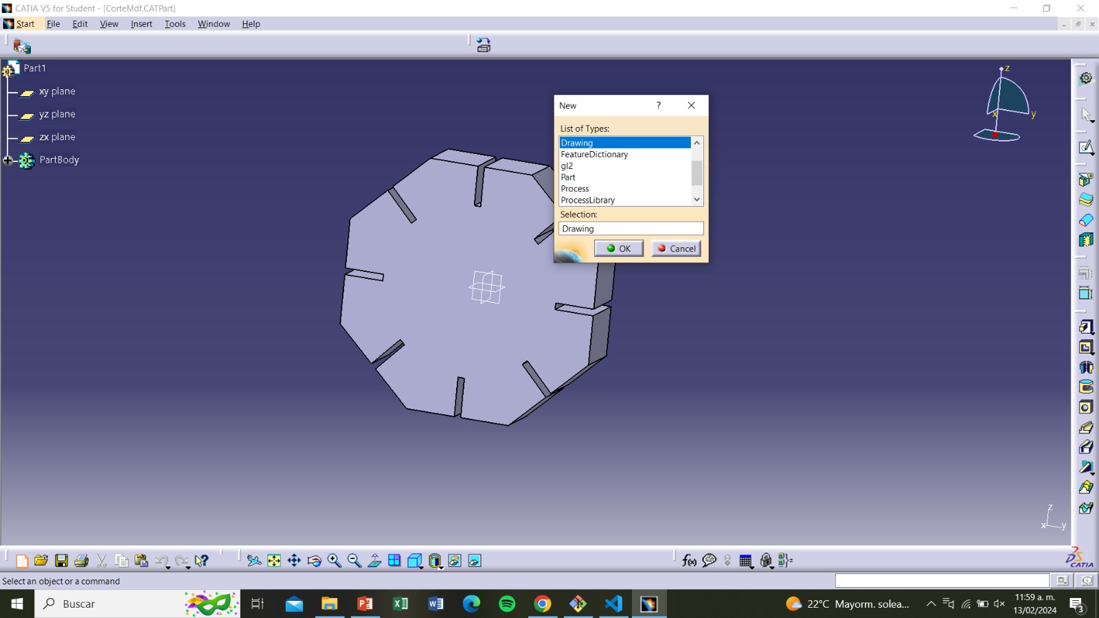
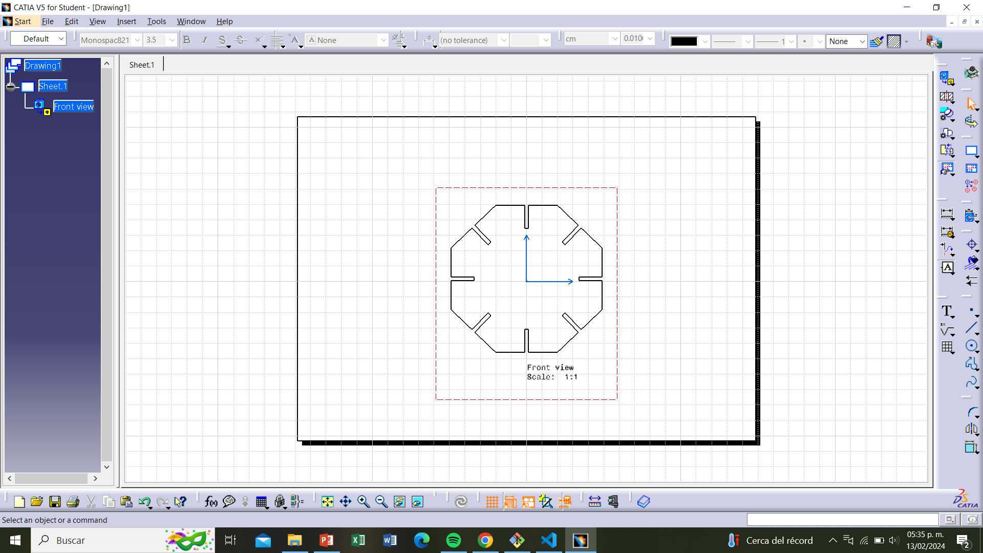
Having the volumetric piece, we need to convert it to a 2D plan. So, we click on "File",
then "new file", and select "drawing", and "ok"
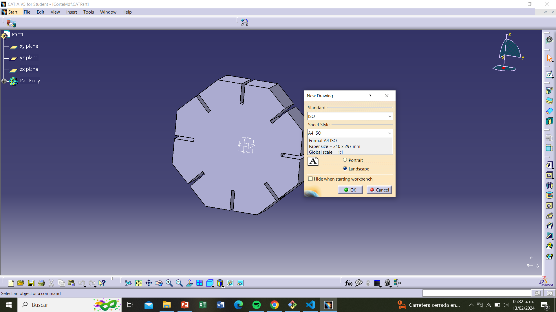
Step 9
"By clicking "ok", the "new drawing" tab will open with format options. We select "A4 ISO"
and then "landscape" and "ok"
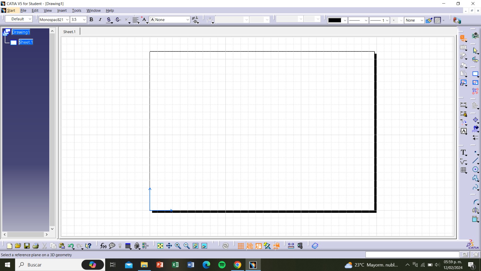
Step 10
The drawing window will open, and then we click on "Front view"
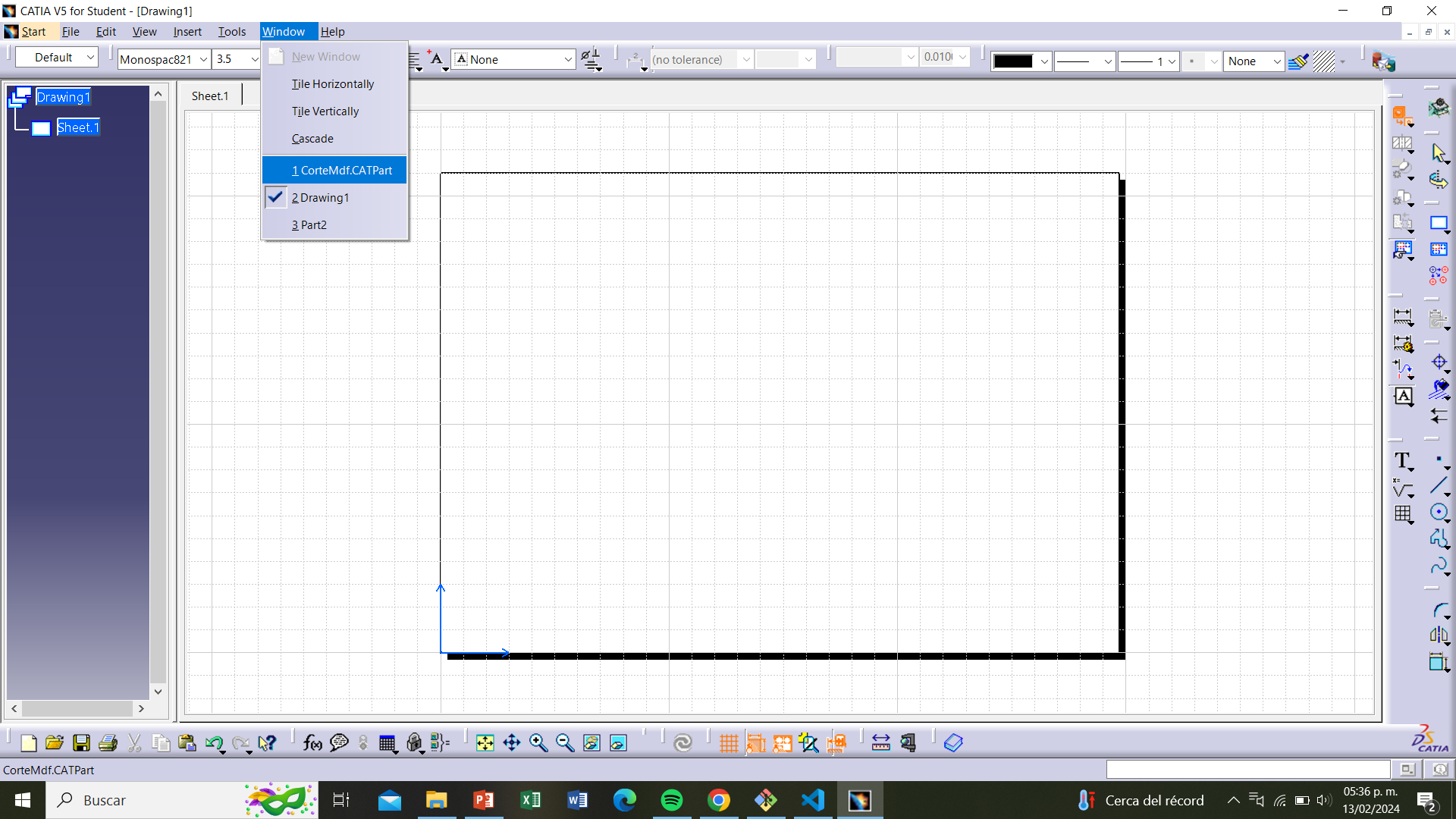
Step 11
We now have to select our piece, so we click on "window" and then on the name of our part,
in this case, it is "CorteMDF"
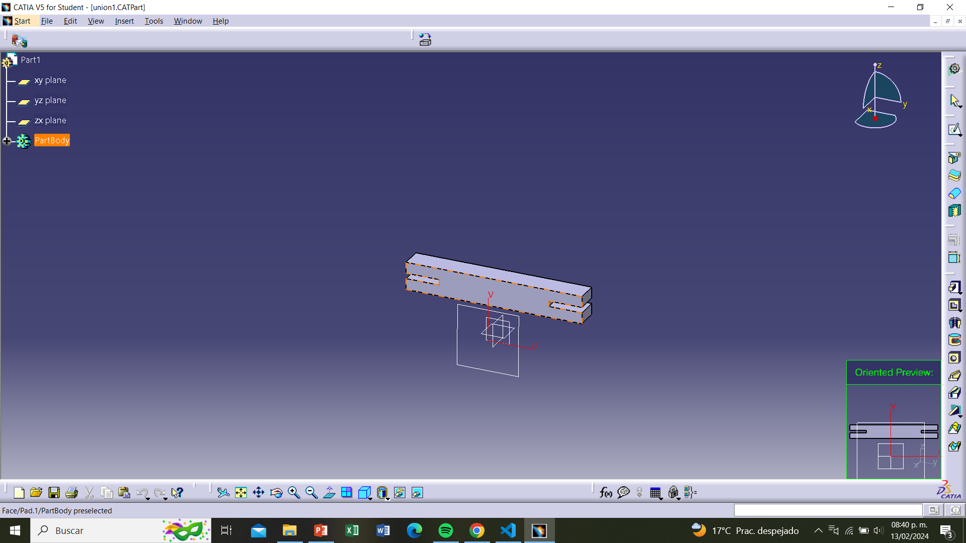
We will be taken to our drawing, here we have to click on the front face.
Step 12
Step 13
We will return to the plane and place the piece in the center.
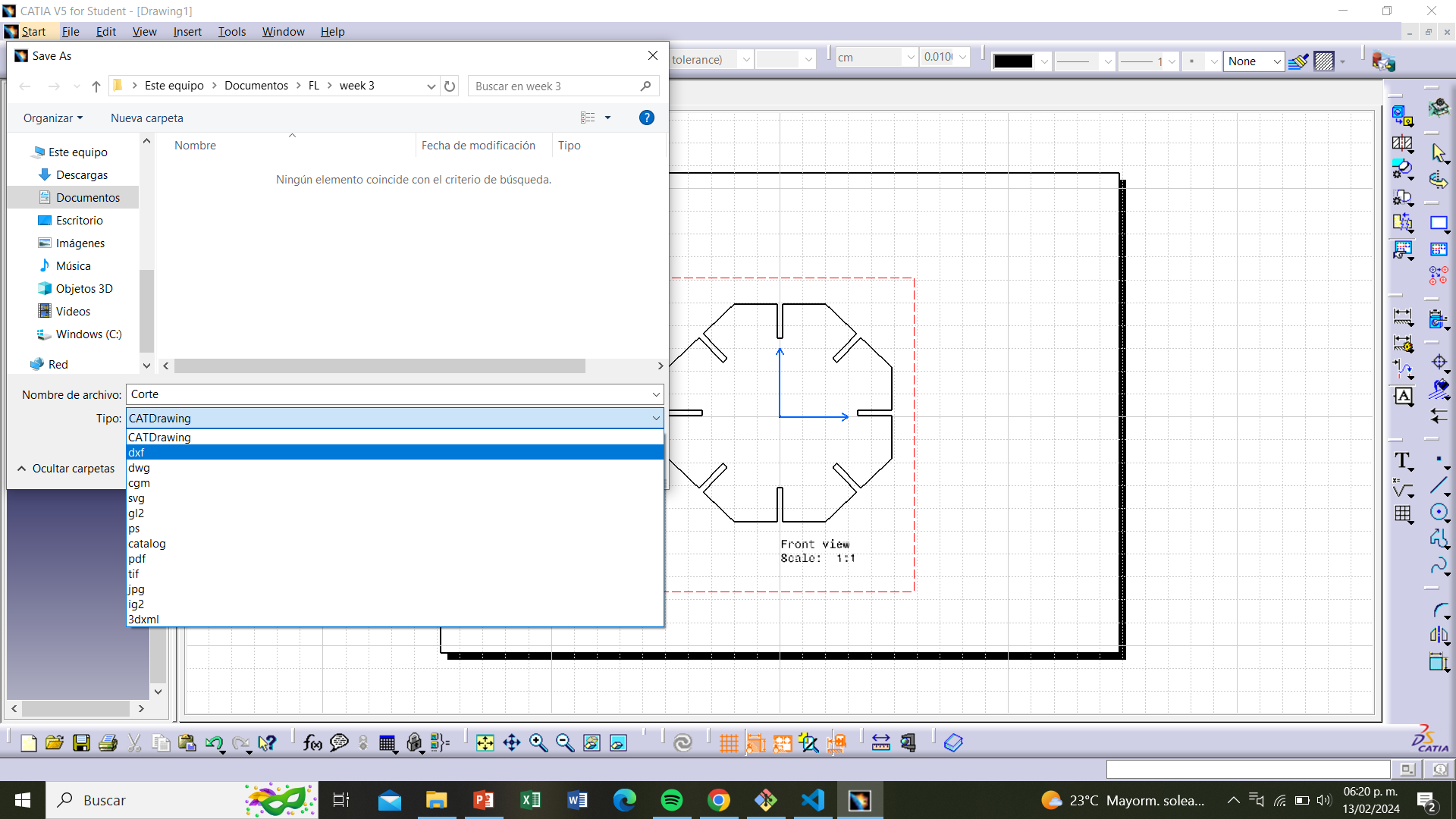
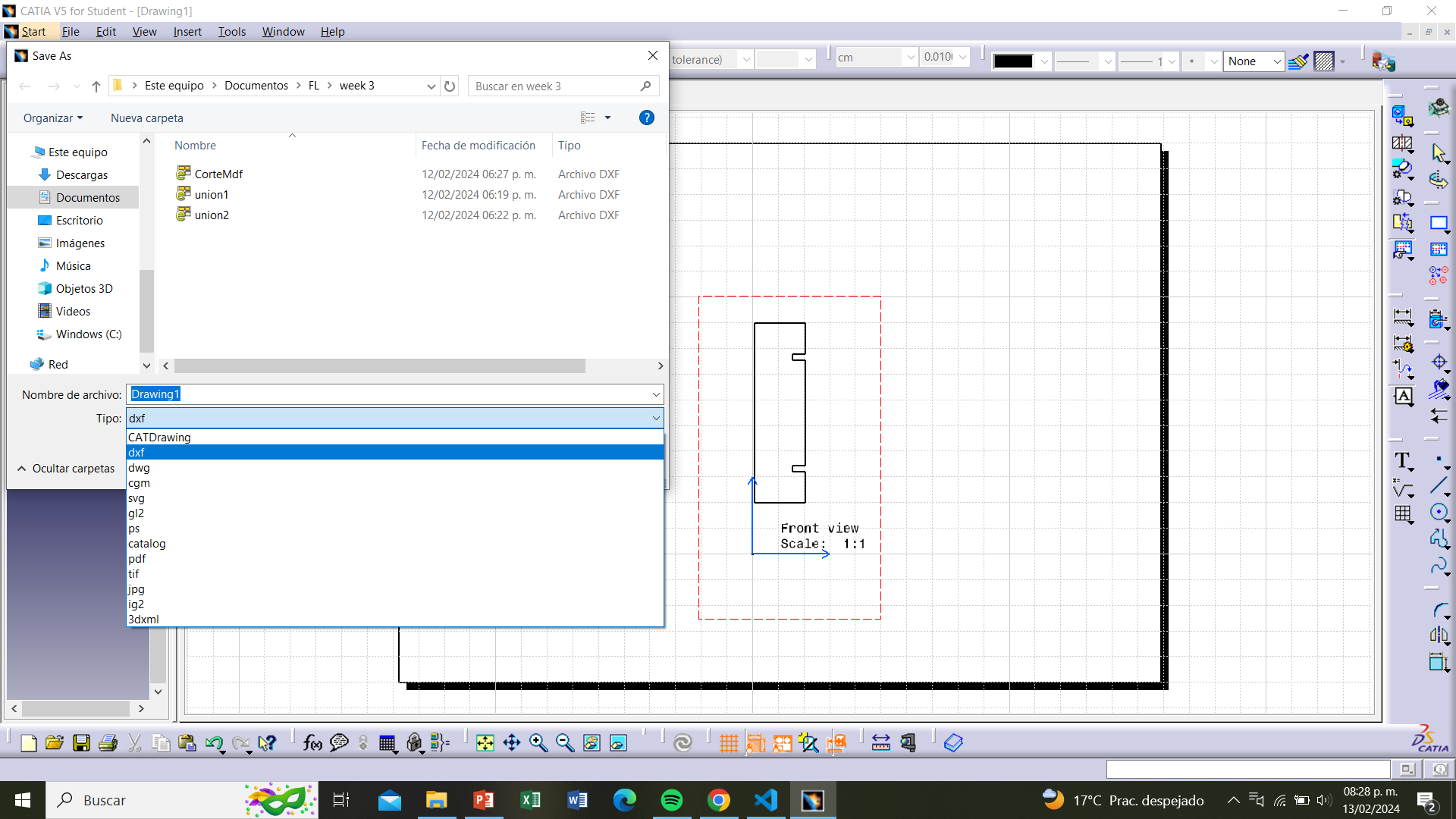
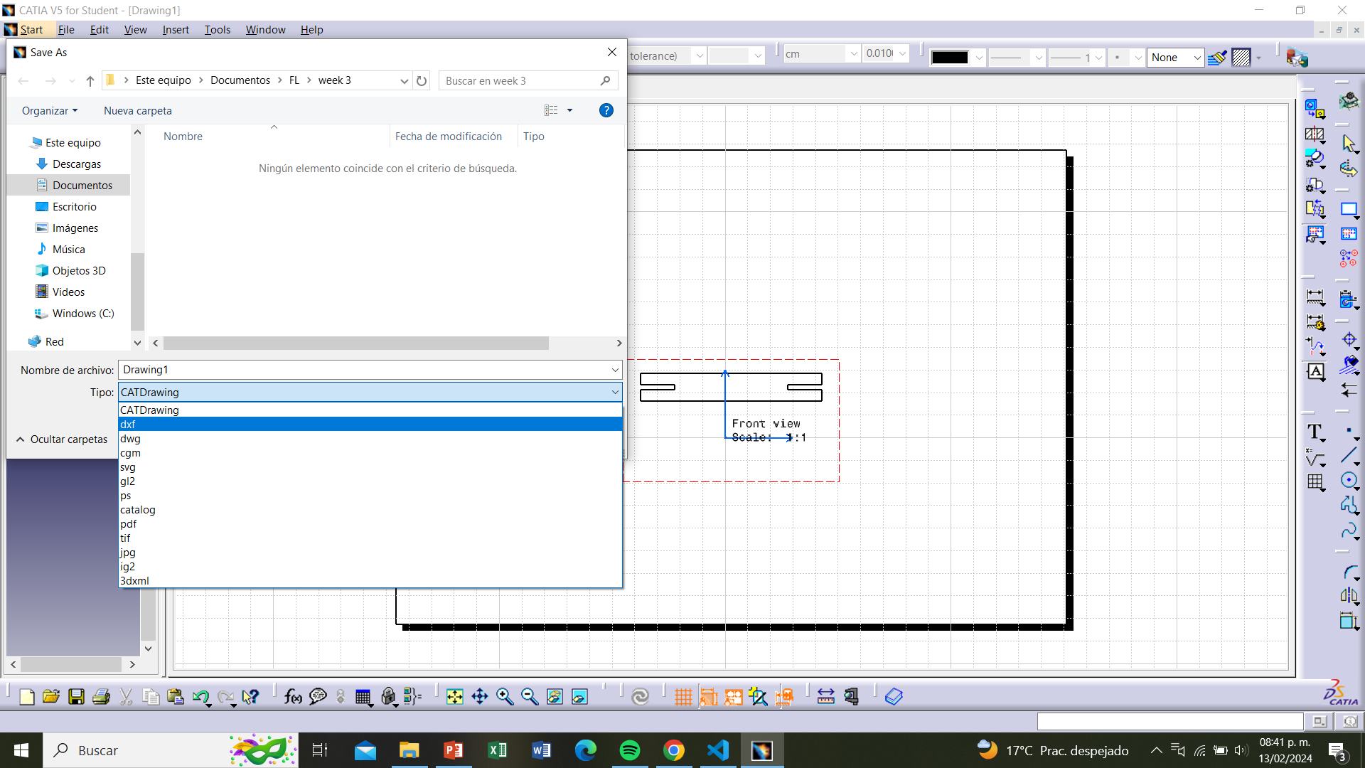
Step 14
We check that everything looks in order and save the file as DXF. To do this,
we click on "file", then "save as", give a name to the file, select "DXF", and save it
where we can find it later for cutting.
Step 14
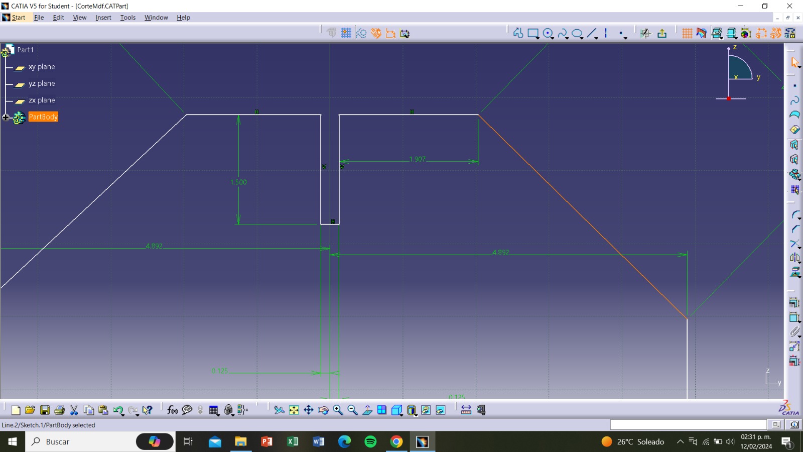
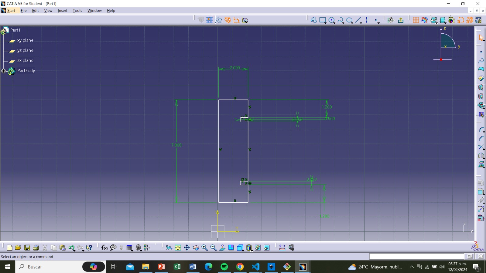
For the vertical joint, we follow the first two steps of the octagonal piece.
From there, using the "profile" tool, we draw the piece with the desired measurements.
Nomenclature
The measurements are as follows:
Height: 7cm
Width: 2cm
Hole width: 0.25cm
Hole width with kerf: (0.25cm-0.0252cm)= 0.2248cm
Hole length: 1.5cm
Step 15
We follow steps 6 and 7 so that the piece looks as follows.
Step 16
We repeat steps 8 to 11 and select the piece.
Step 17
We follow steps 13 and 14 to save the document in DXF format.
Step 18
Now, for the horizontal joint, it's practically the same as the vertical joint.
We follow the first two steps of the octagonal piece. From there, using the "profile" tool,
we draw the piece with the desired measurements.
The measurements are as follows:
Height: 1.25cm
Width: 8cm
Hole width: 0.25cm
Hole width with kerf: (0.25cm-0.0252cm)= 0.2248cm
Hole length: 1.5cm
Step 19
We follow steps 6 and 7 so that the piece looks as follows.
Step 20
We repeat steps 8 to 11 and select the piece.
Step 21
We follow steps 13 and 14 to save the document in DXF format.
Step 22
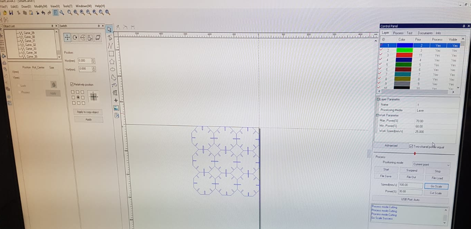
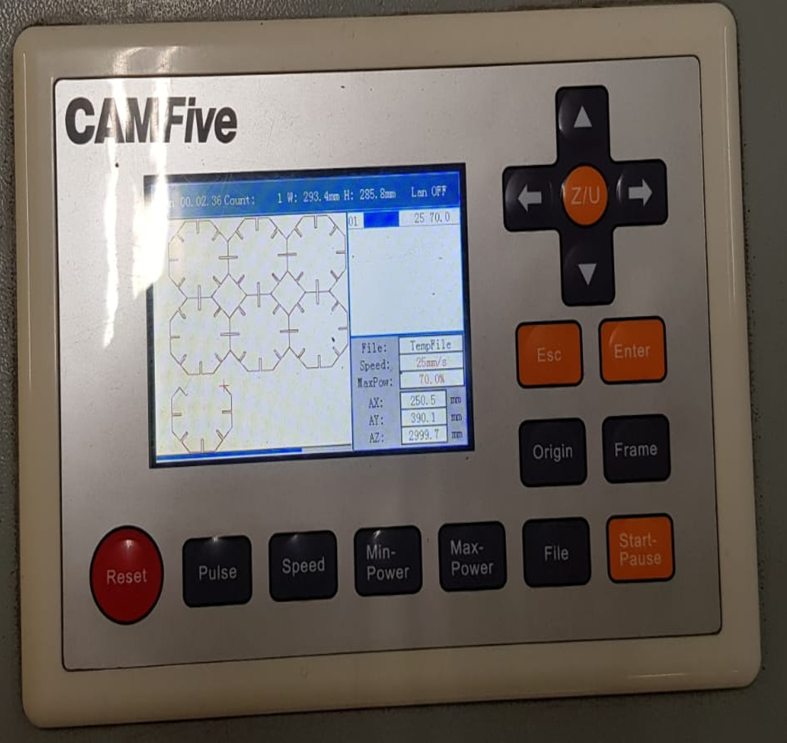
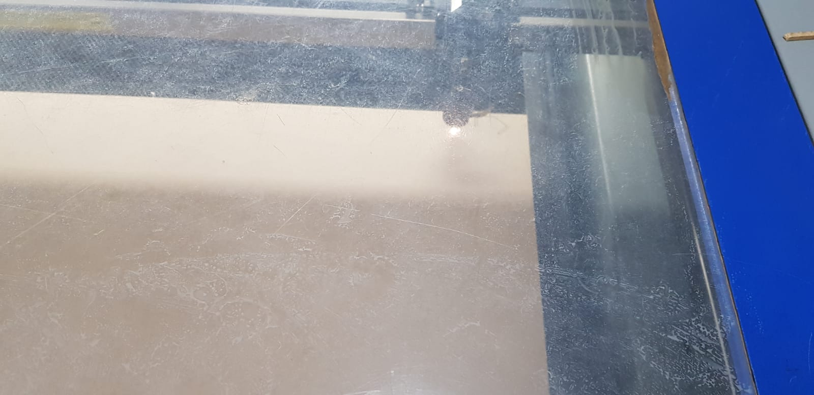
Having the documents ready for cutting, we head towards the cutting machine,I used the
CFL-CMA1080K.
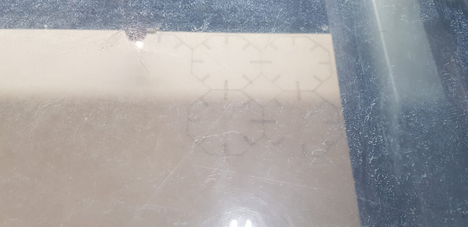
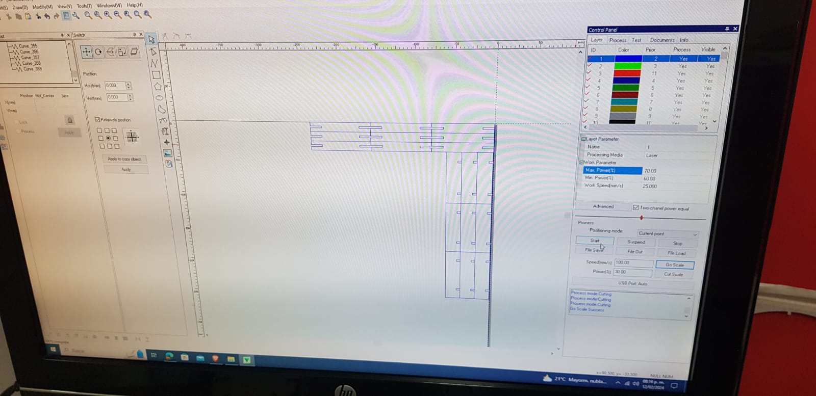
We now place the MDF board, open the smartcarve 4.3 program, and load our document. I started with the document containing the octagonal
pieces. The drawing positioned itself in the upper right corner, with a right-click and "clone", I placed three rows and three columns of the drawing
to cut 9 pieces.
Step 23
With the arrows, we position the laser at the desired coordinates.
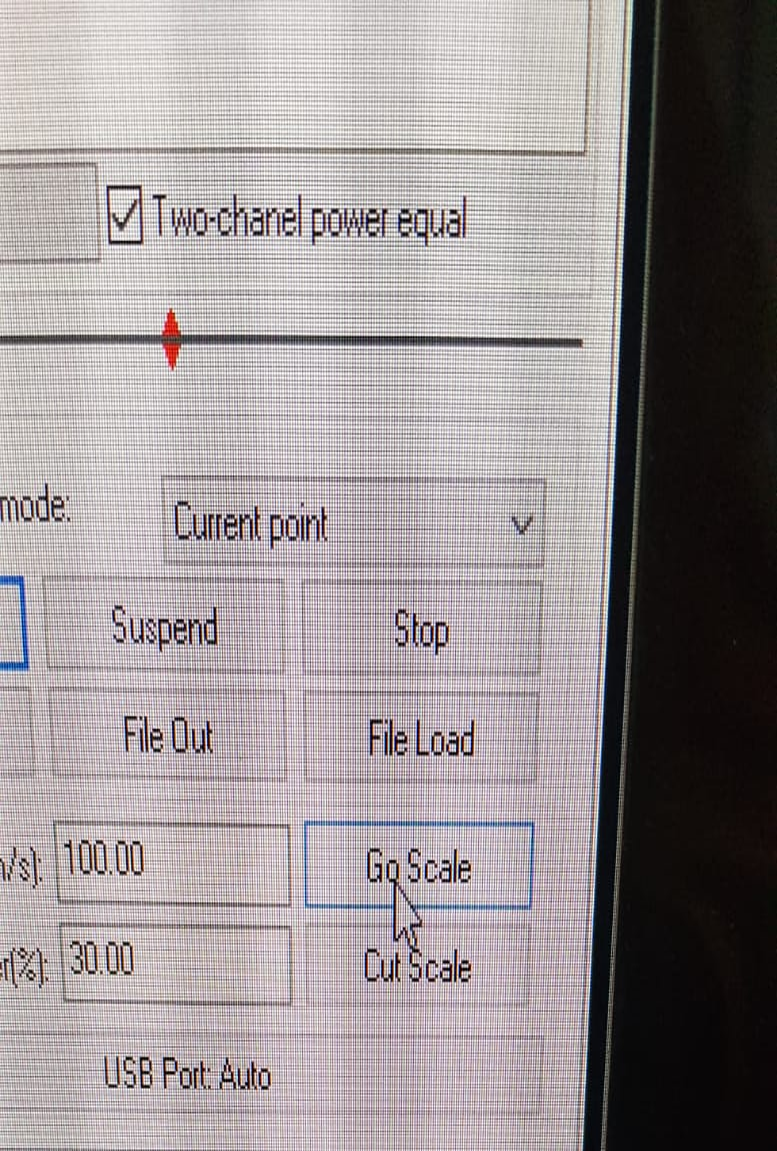
Step 24
To verify that the laser cuts in the desired place, click on "go scale",
and we will see the path that the laser will follow.
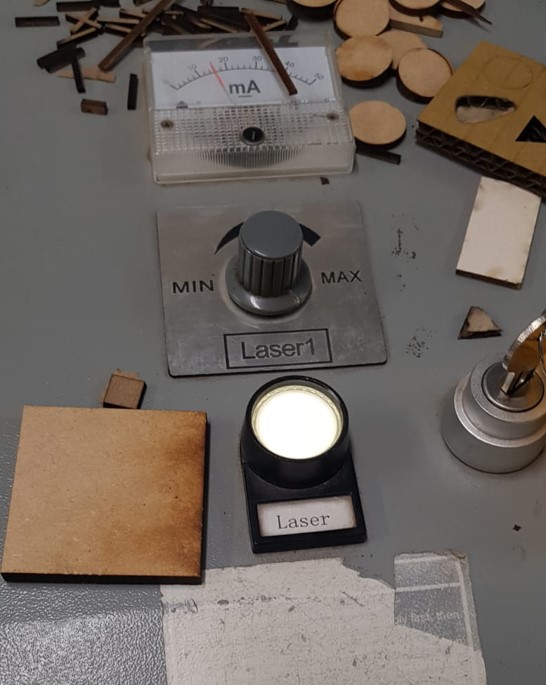
Step 25
Once the laser is well positioned, we turn it on by pressing the power button and
adjust the knob to maximum power.
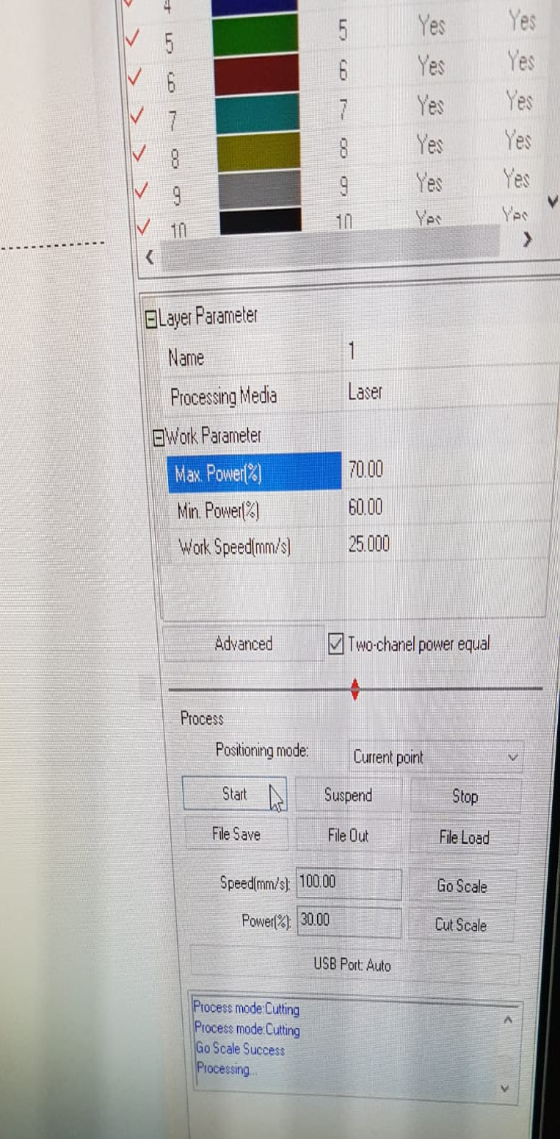
Step 26
Having all this ready, we click on "start", and the machine will begin cutting.
Step 27
For the other two pieces, we repeat step 22, but this time we open both documents
and place the pieces to avoid having to repeat the process.
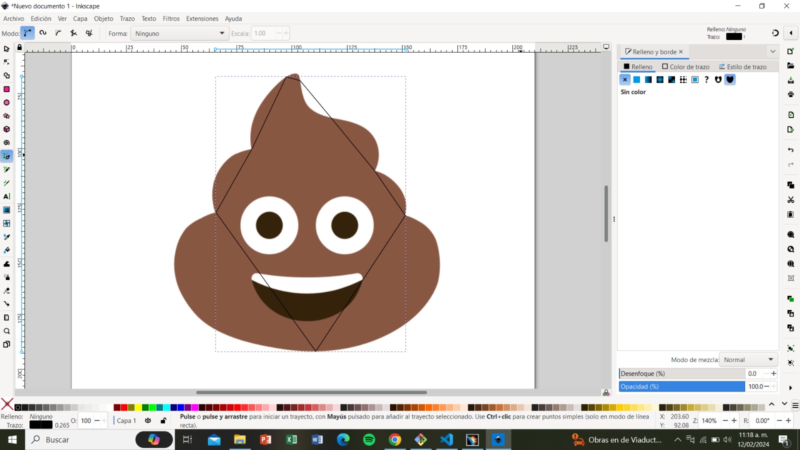
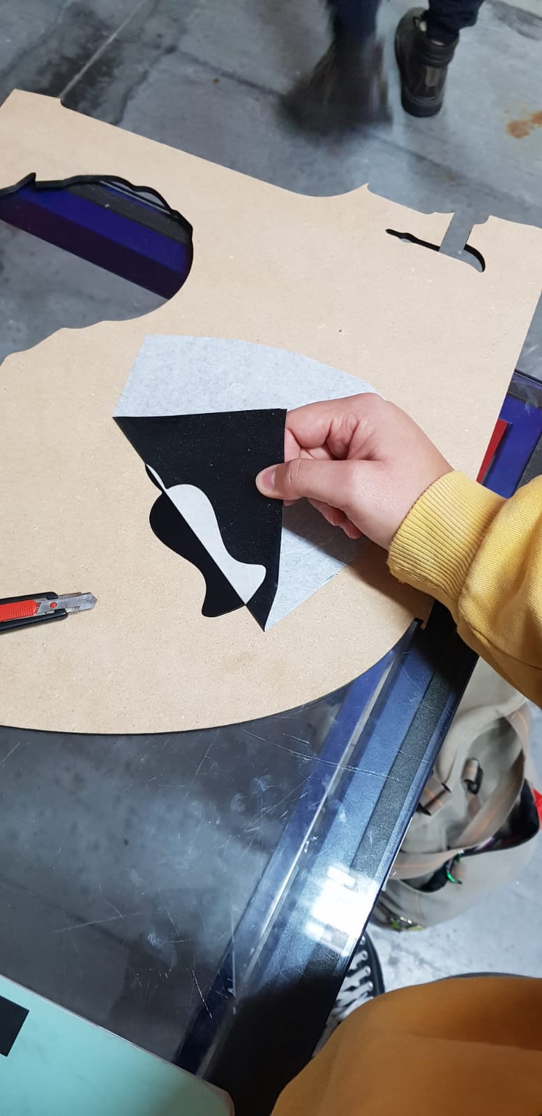
For the second personal assignment, we need to create a vectorized drawing to print it on vinyl
Step 1
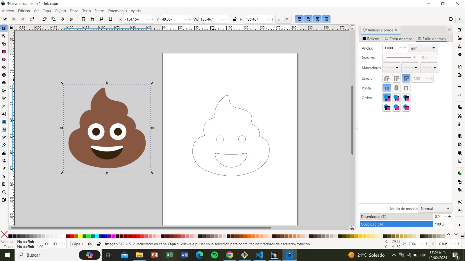
Select the image and paste it into the desired program. I will use Inkscape.
having the reference image, we will use the "pen tool" to trace the outlines.
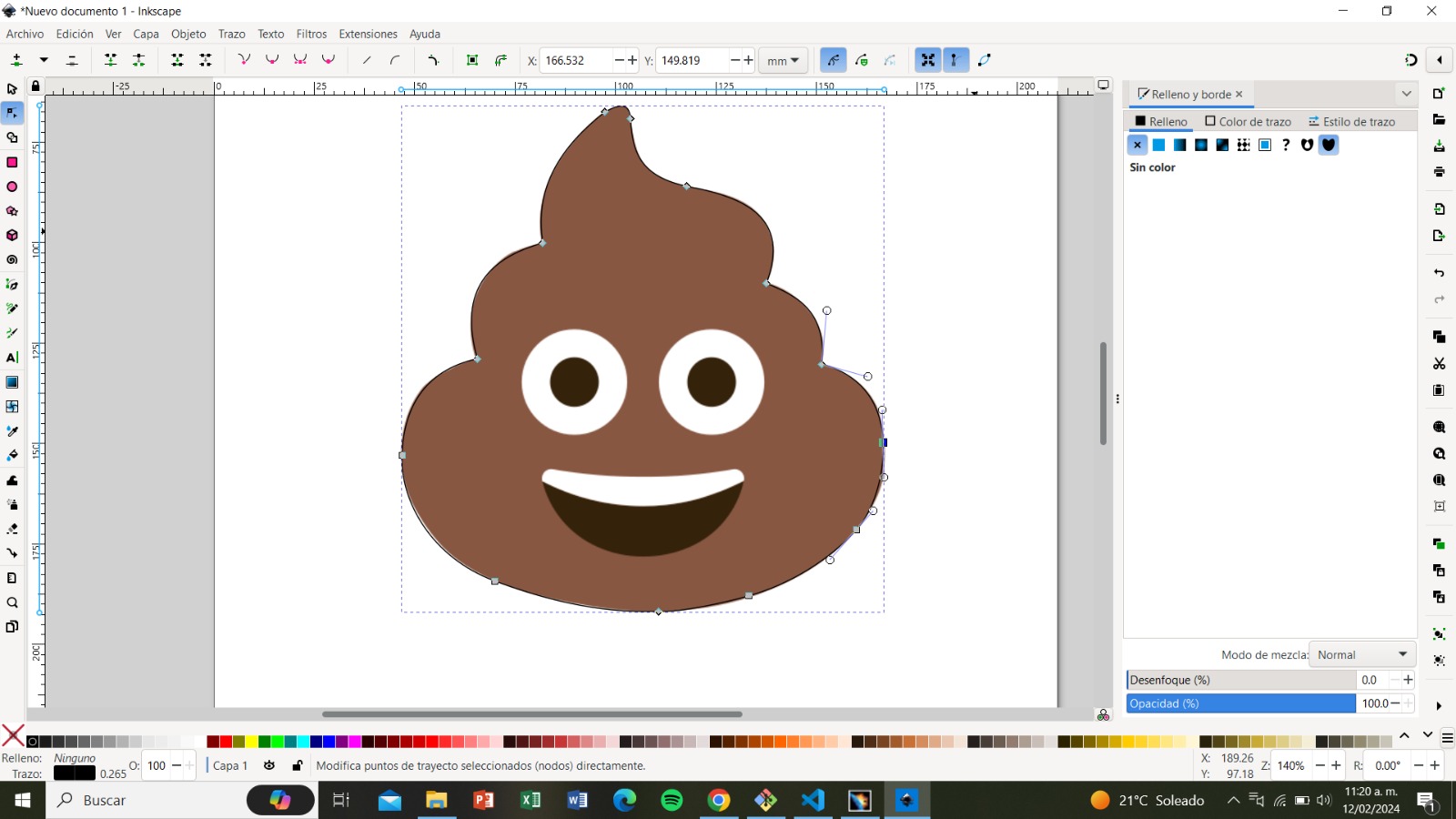
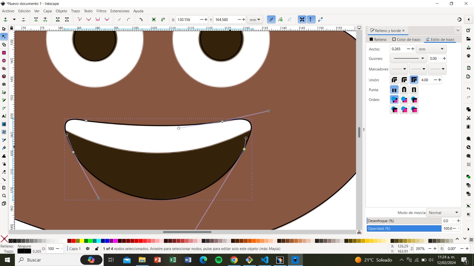
Step 2
Once we have the outline, we use the "node tool" to adjust the lines into place.
Step 3
We compare both images to ensure that everything is in order.
Step 4
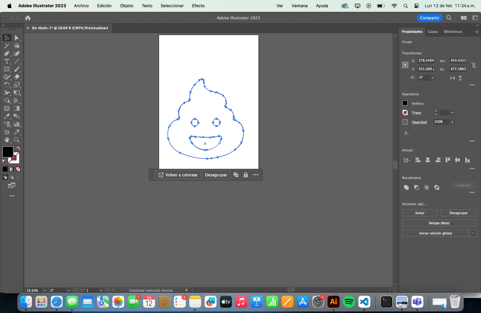
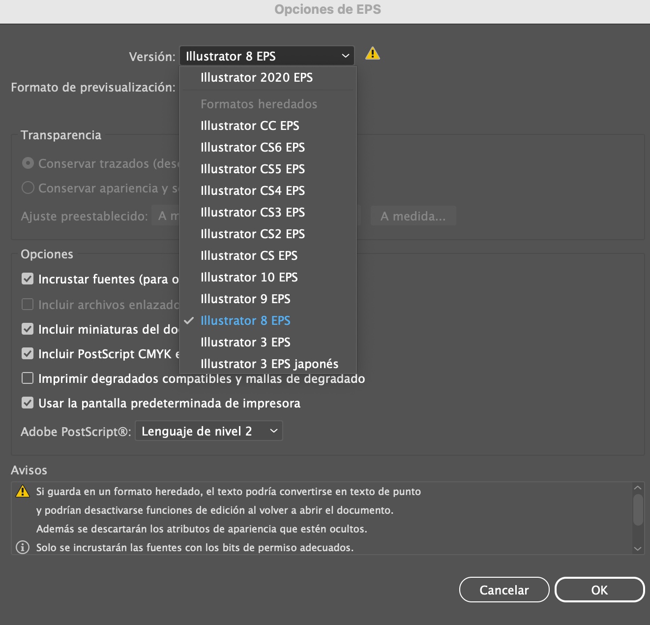
To print on vinyl, the machine only reads EPS8 documents, so we transfer the drawing to Illustrator
and save it in that format.
Step 5
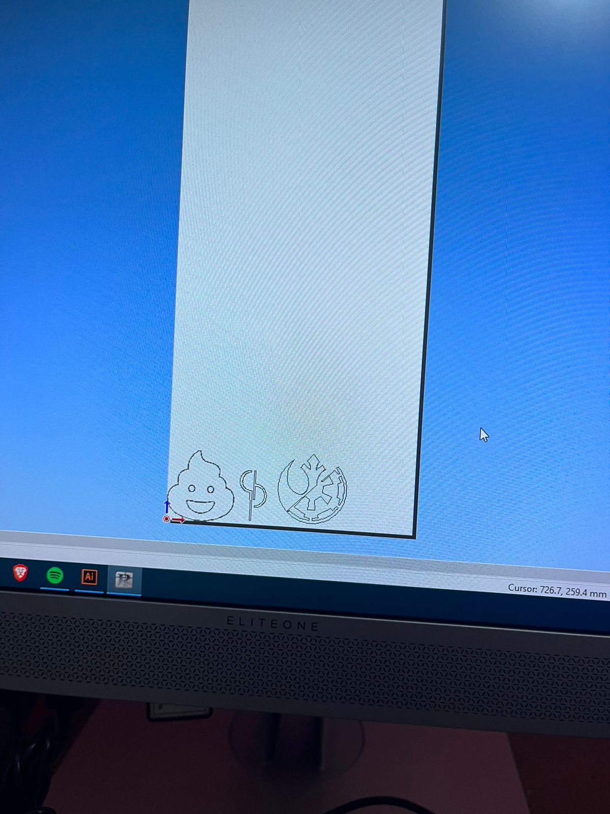
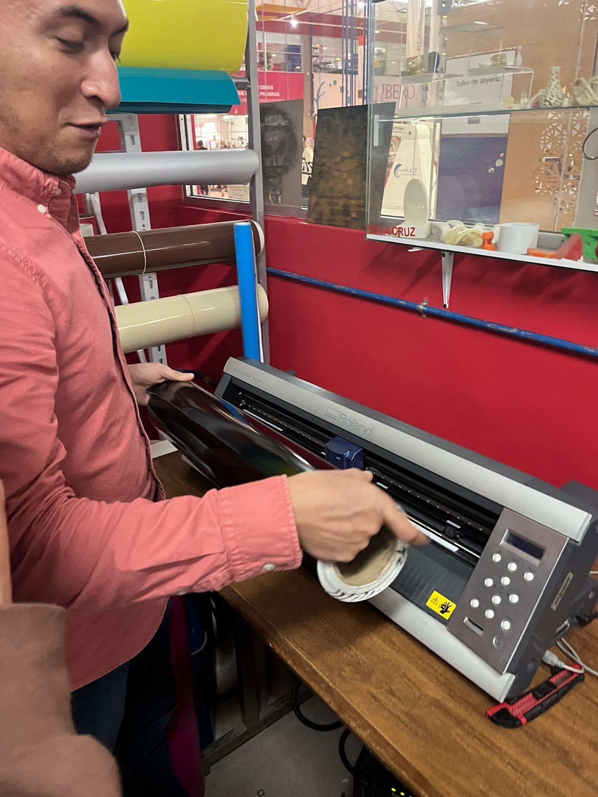
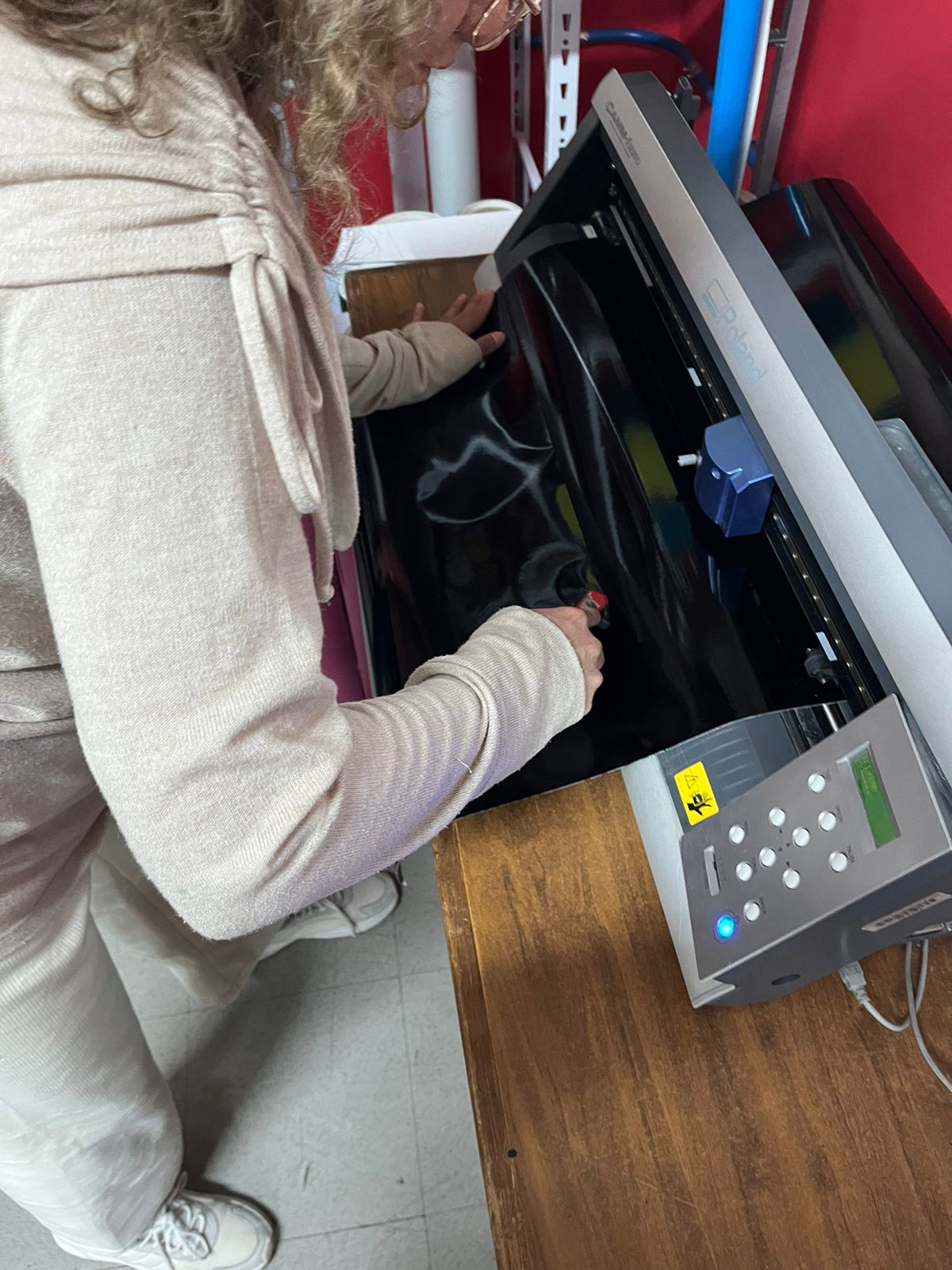
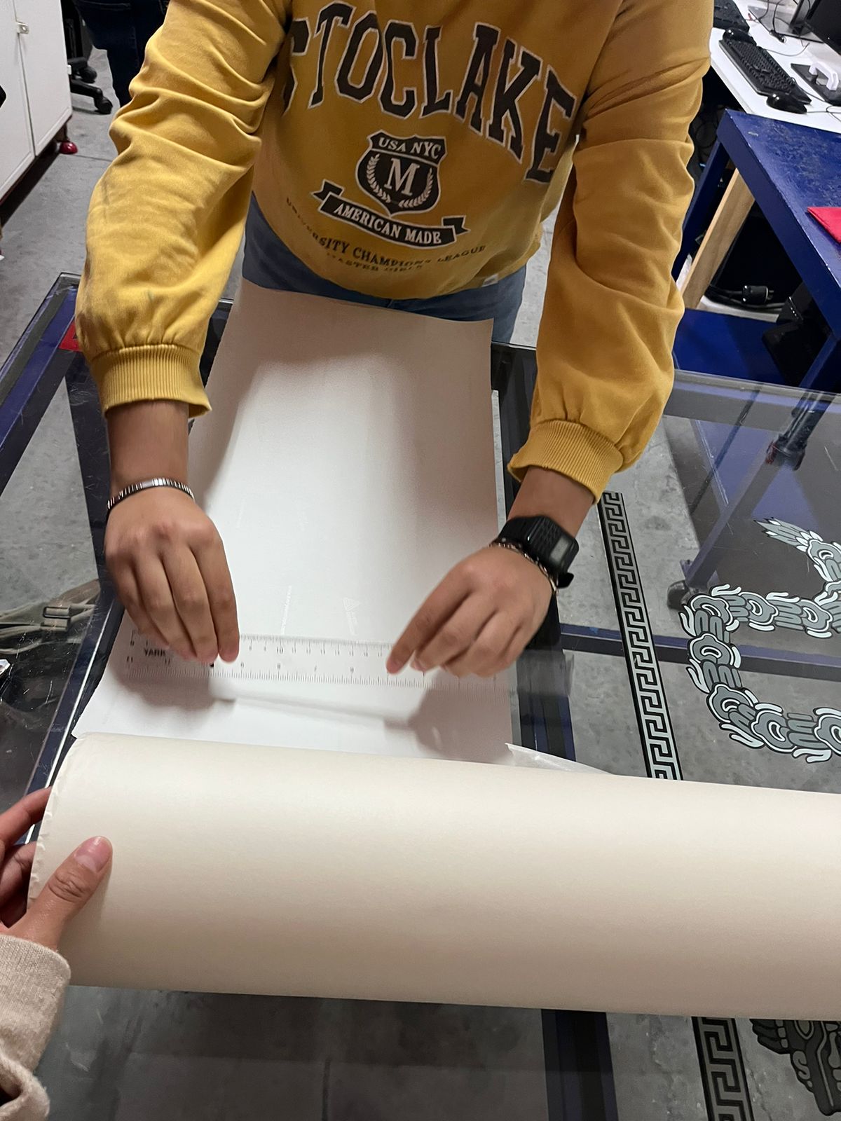
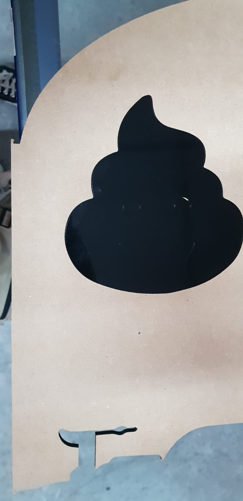
To cut it, we open the drawing in the program and load the vinyl roll of the desired color into the machine.
Step 6
Once the machine has cut the vinyl, we trim the part where our design is located.
Step 7
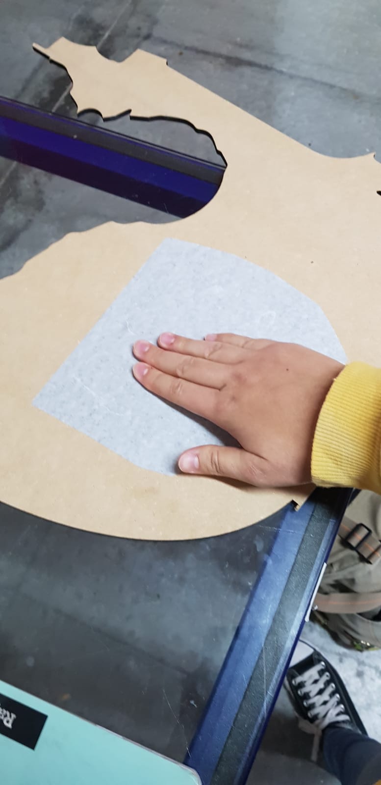
We place transfer paper over the design and press down to ensure it adheres well.
Step 8
We remove the protective layer from the vinyl and stick the design onto the desired surface.
Step 9
We remove the transfer paper and peel away the excess vinyl to reveal the design.


