6. Embedded Programming
Individual assignment
1. Code
This week, I revisited the code provided by our local fab during week 4, when we were working on our printed circuit board (PCB) project. The code, originally is written in C++ and I contemplated the prospect of adapting it to be compatible with both Micro Python and Circuit Python environments.
This is the original code.
// the setup function runs once when you press reset or power the board
void setup() {
  // initialize digital pin LED_BUILTIN as an output.
  pinMode(D1, INPUT);
  pinMode(26, OUTPUT);
  digitalWrite(26, HIGH);
  pinMode(D7, OUTPUT);
  digitalWrite(26, HIGH);
  pinMode(D6, OUTPUT);
  digitalWrite(26, HIGH);

  //pinMode(PIN_LED_R, OUTPUT);
  //pinMode(PIN_LED_G, OUTPUT);
  //pinMode(PIN_LED_B, OUTPUT);
  //digitalWrite(PIN_LED_R, HIGH);
  //digitalWrite(PIN_LED_G, HIGH);
  //digitalWrite(PIN_LED_B, HIGH);
}

// the loop function runs over and over again forever
void loop() {
  /*digitalWrite(PIN_LED_B, HIGH);  // turn the LED on (HIGH is the voltage level)
  delay(1000);                      // wait for a second
  digitalWrite(PIN_LED_B, LOW);   // turn the LED off by making the voltage LOW
  delay(1000);*/                      // wait for a second

  digitalWrite(26, digitalRead(D1));  // turn the LED on (HIGH is the voltage level)
  digitalWrite(D6, HIGH);  // turn the LED on (HIGH is the voltage level)
  digitalWrite(D7, HIGH);  // turn the LED on (HIGH is the voltage level)
  delay(1000);                      // wait for a second
  digitalWrite(26, LOW);   // turn the LED off by making the voltage LOW
  digitalWrite(D6, LOW);   // turn the LED off by making the voltage LOW
  digitalWrite(D7, LOW);   // turn the LED off by making the voltage LOW
  delay(1000);

}
Afterwards, I embarked on the task of transitioning the code to Circuit Python. My initial step involved updating the firmware of the RP2040 to ensure compatibility and recognition by Mu, a dedicated Python code editor.
I used this guide toupdate de firmware.
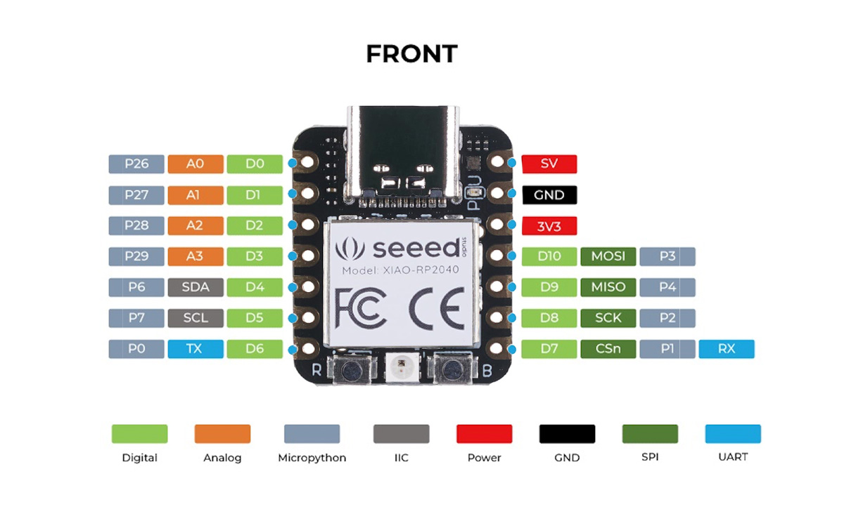
Using the assistance of ChatGPT, I successfully translated the code into Circuit Python. However, upon implementation, I encountered issues with its functionality because the leds does not turn on. To troubleshoot and rectify the situation, I delved into the process of adjusting the input and output pins. My reference for this task was an informative image from the RP2040 documentation, which guide me through the necessary pin configuration changes.
This is the code ChatGPT gave me.
import board
import digitalio
import time

# Configurar los pines
pin_D1 = digitalio.DigitalInOut(board.D1)
pin_D1.direction = digitalio.Direction.INPUT
pin_26 = digitalio.DigitalInOut(board.D26)
pin_26.direction = digitalio.Direction.OUTPUT
pin_D7 = digitalio.DigitalInOut(board.D7)
pin_D7.direction = digitalio.Direction.OUTPUT
pin_D6 = digitalio.DigitalInOut(board.D6)
pin_D6.direction = digitalio.Direction.OUTPUT

pin_26.value = True
pin_D7.value = True
pin_D6.value = True

while True:
pin_26.value = pin_D1.value  # Encender el LED (HIGH es el nivel de voltaje)
pin_D6.value = True  # Encender el LED (HIGH es el nivel de voltaje)
pin_D7.value = True  # Encender el LED (HIGH es el nivel de voltaje)
time.sleep(1)  # Esperar un segundo
pin_26.value = False  # Apagar el LED haciendo que el voltaje sea BAJO
pin_D6.value = False  # Apagar el LED haciendo que el voltaje sea BAJO
pin_D7.value = False  # Apagar el LED haciendo que el voltaje sea BAJO
time.sleep(1)
And this is the final code for Circuit Python.
import board
import digitalio
import time

# Configurar los pines
pin_D1 = digitalio.DigitalInOut(board.D1)
pin_D1.direction = digitalio.Direction.INPUT
pin_D0 = digitalio.DigitalInOut(board.D0)
pin_D0.direction = digitalio.Direction.OUTPUT
pin_D7 = digitalio.DigitalInOut(board.D7)
pin_D7.direction = digitalio.Direction.OUTPUT
pin_D6 = digitalio.DigitalInOut(board.D6)
pin_D6.direction = digitalio.Direction.OUTPUT

pin_D0.value = True
pin_D7.value = True
pin_D6.value = True

while True:
pin_D0.value = pin_D1.value  # Encender el LED (HIGH es el nivel de voltaje)
pin_D6.value = True  # Encender el LED (HIGH es el nivel de voltaje)
pin_D7.value = True  # Encender el LED (HIGH es el nivel de voltaje)
time.sleep(1)  # Esperar un segundo
pin_D0.value = False  # Apagar el LED haciendo que el voltaje sea BAJO
pin_D6.value = False  # Apagar el LED haciendo que el voltaje sea BAJO
pin_D7.value = False  # Apagar el LED haciendo que el voltaje sea BAJO
time.sleep(1)
With this final code the pcb work as intended. (Video)
Subsequently, I revisited the same documentation page and installed the MicroPython-compatible firmware. Employing Thonny as my Python IDE of choice, I proceeded to test the code. However, akin to the experience with Circuit Python, I encountered similar issues requiring me to recalibrate the input and output pins.
from machine import Pin
import time

# initialize digital pin LED_BUILTIN as an output.
pin_D1 = Pin(5, Pin.IN)  # D1 on NodeMCU corresponds to GPIO5
pin_26 = Pin(26, Pin.OUT)
pin_D7 = Pin(13, Pin.OUT)  # D7 on NodeMCU corresponds to GPIO13
pin_D6 = Pin(12, Pin.OUT)  # D6 on NodeMCU corresponds to GPIO12

pin_26.value(1)
pin_D7.value(1)
pin_D6.value(1)

while True:
pin_26.value(pin_D1.value())  # turn the LED on (HIGH is the voltage level)
pin_D6.value(1)  # turn the LED on (HIGH is the voltage level)
pin_D7.value(1)  # turn the LED on (HIGH is the voltage level)
time.sleep(1)  # wait for a second
pin_26.value(0)  # turn the LED off by making the voltage LOW
pin_D6.value(0)  # turn the LED off by making the voltage LOW
pin_D7.value(0)  # turn the LED off by making the voltage LOW
time.sleep(1)
And this is the final code for Micro Python.
from machine import Pin
import time

# initialize digital pin LED_BUILTIN as an output.
pin_P27 = Pin(27, Pin.IN)  # D1 on NodeMCU corresponds to GPIO5
pin_P26 = Pin(26, Pin.OUT)
pin_P1 = Pin(1, Pin.OUT)  # D7 on NodeMCU corresponds to GPIO13
pin_P0 = Pin(0, Pin.OUT)  # D6 on NodeMCU corresponds to GPIO12

pin_P26.value(1)
pin_P1.value(1)
pin_P0.value(1)

while True:
pin_P26.value(pin_P27.value())  # turn the LED on (HIGH is the voltage level)
pin_P0.value(1)  # turn the LED on (HIGH is the voltage level)
pin_P1.value(1)  # turn the LED on (HIGH is the voltage level)
time.sleep(1)  # wait for a second
pin_P26.value(0)  # turn the LED off by making the voltage LOW
pin_P0.value(0)  # turn the LED off by making the voltage LOW
pin_P1.value(0)  # turn the LED off by making the voltage LOW
time.sleep(1)
With this final code the pcb work as intended. (Video)