3. Computer-Controlled Cutting
Individual assignments
1. Creating my parametric construction kit
This week, I've been contemplating various approaches to craft a parametric design reminiscent of assembling Lego bricks. It sparked a nostalgic journey into my childhood when my parents gifted me plastic toys featuring circular pieces that interlocked seamlessly. Drawing inspiration from these childhood memories, my concept evolved into an attempt to recreate those connecting elements, enhancing them by incorporating additional slots. The aim was to facilitate the assembly of a more diverse range of pieces, enabling the creation of an expansive array of designs.
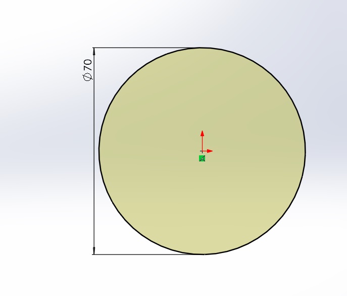
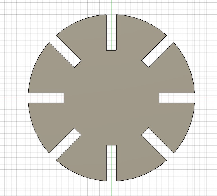
I embarked on the initial phase by conceptualizing a circle with a diameter of 70mm, envisioning it as the foundational element for what would become the cornerstone of my parametric design.
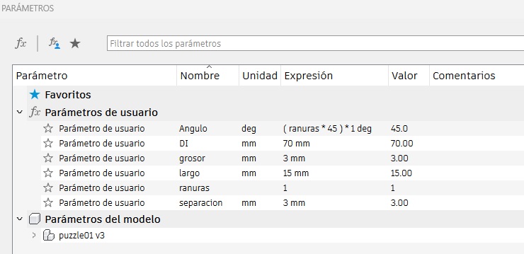
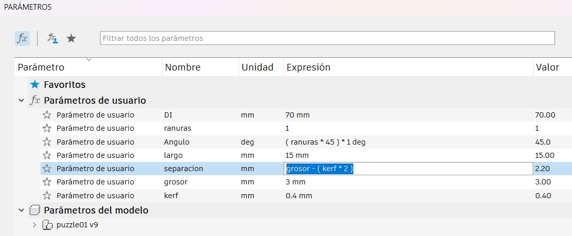
In my quest to forge a parametric design, I meticulously pondered the variables that needed to be imbued with parametric qualities. Key considerations included the radius of the circular base, the number and placement of slots, and the overall geometry that would govern the interplay of these connective elements.
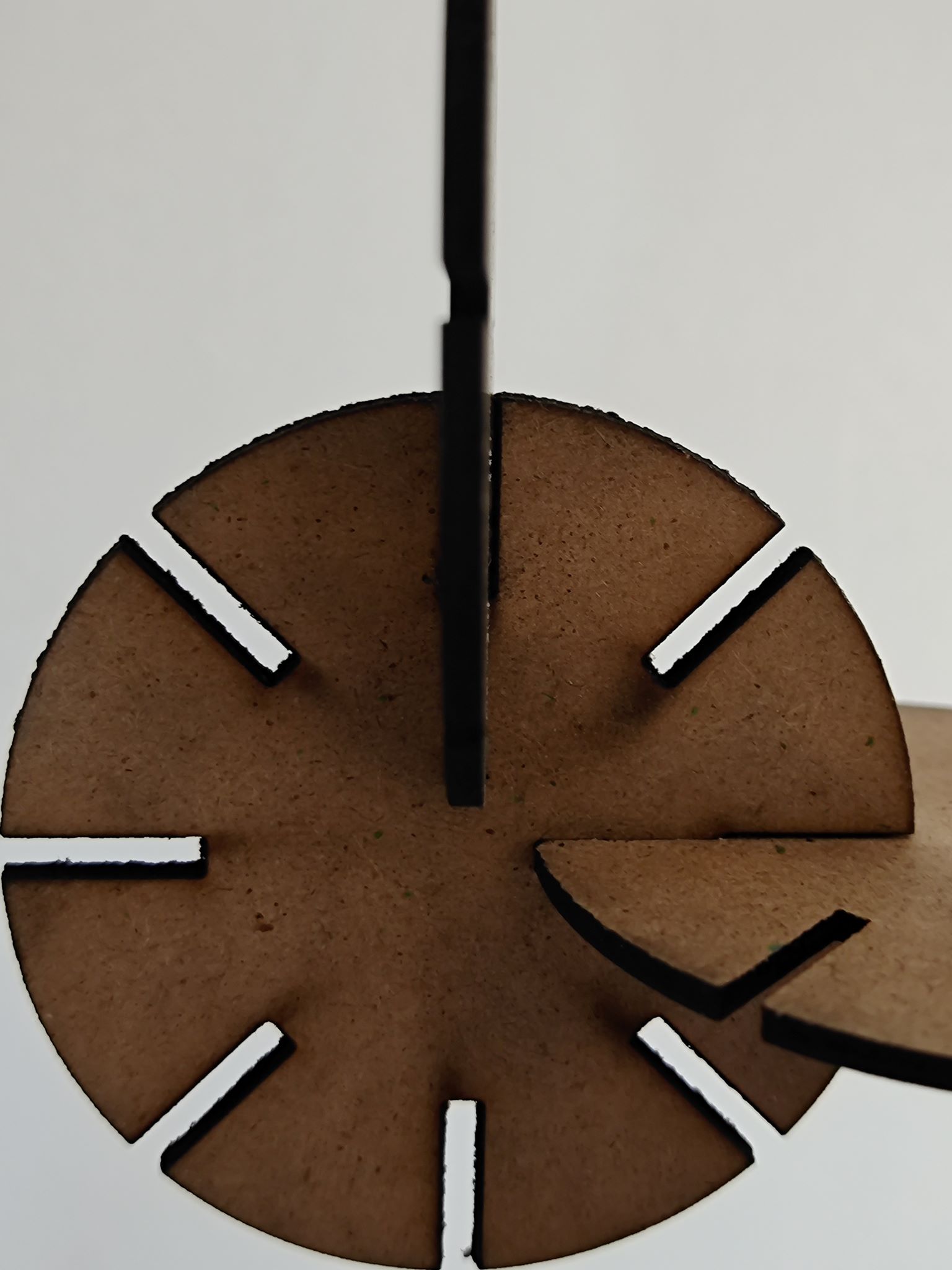
Once the essential variables were identified, my focus shifted towards crafting the design of the slots. I delved into the intricacies of slot placement, shape, and orientation, contemplating the visual and structural impact each modification could bring. This led me to create a circular arrangement housing eight slots, a configuration carefully chosen for its balance and adaptability. What's intriguing about this approach is that the number and positioning of these slots became dynamic, directly tied to the parametric variables I had established earlier.
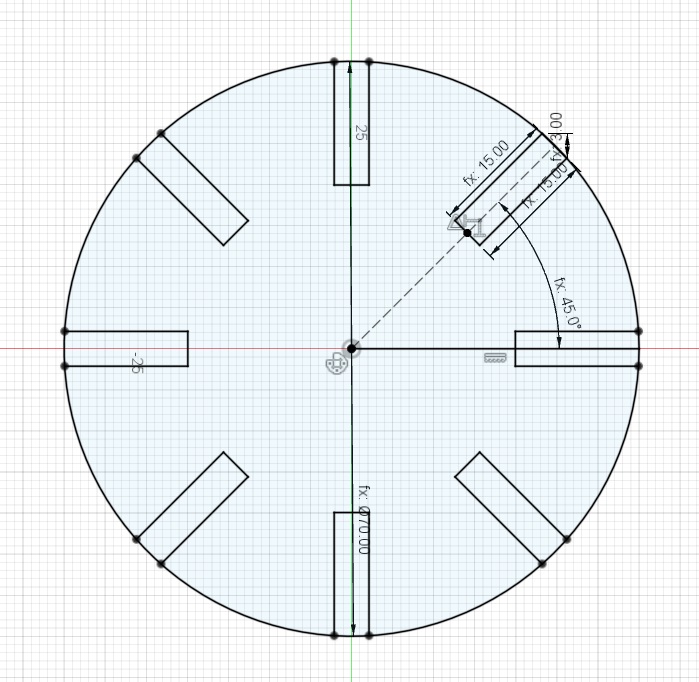
Then, I cut the slots to get the final shape of the figure.
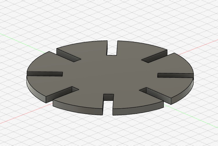
Following the cutting of the slots, I transitioned into the realm of three-dimensional design to gain a comprehensive visualization of the resulting figure.
Subsequently, executed the crucial step of exporting the design file into the DXF (Drawing Exchange Format) format, a standard file format widely recognized in the realm of computer-aided design (CAD). By exporting the design to DXF, I laid the groundwork for the next stage, which involved translating the digital blueprint into a tangible reality using a cutting machine. The DXF file encapsulated not only the aesthetic details of the parametric design but also the vital parametric variables that dictated the dimensions and configurations of the slots.
I used the program SmartCarve to import the DXF file so the laser cutter can cut my design. This program is only avalible on the computer that is connected to the laser. After setting up my desing i use power of 80 and speed of 50 so the machine can clean cut the MDF.
I used the laser cutter to cut the final shape of my desing, however i had some problems.
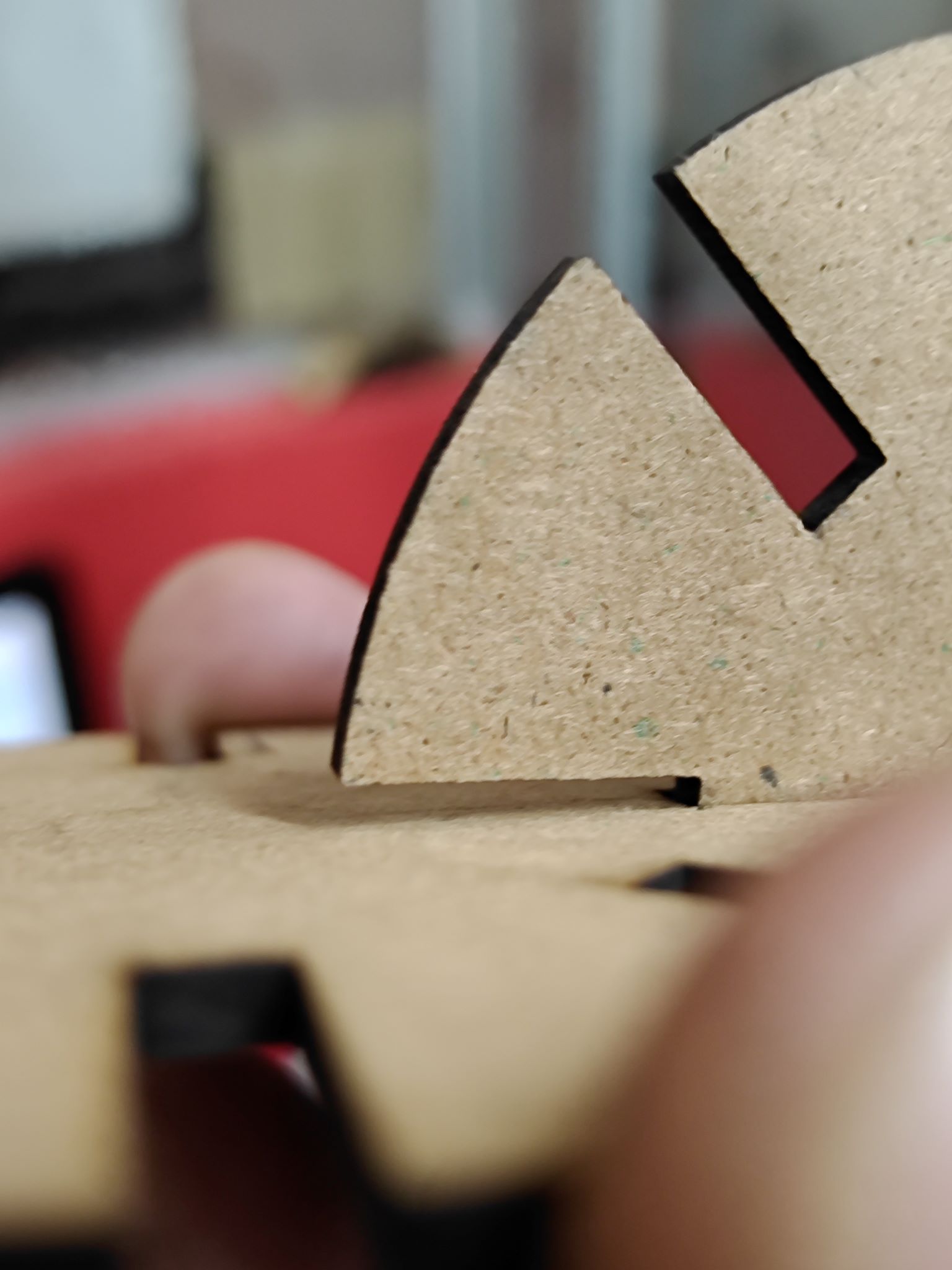
The material was not 3mm thick, the material was 2.4mm thick. So i need to made ajustments in my desing to fit the 2.4mm thick.
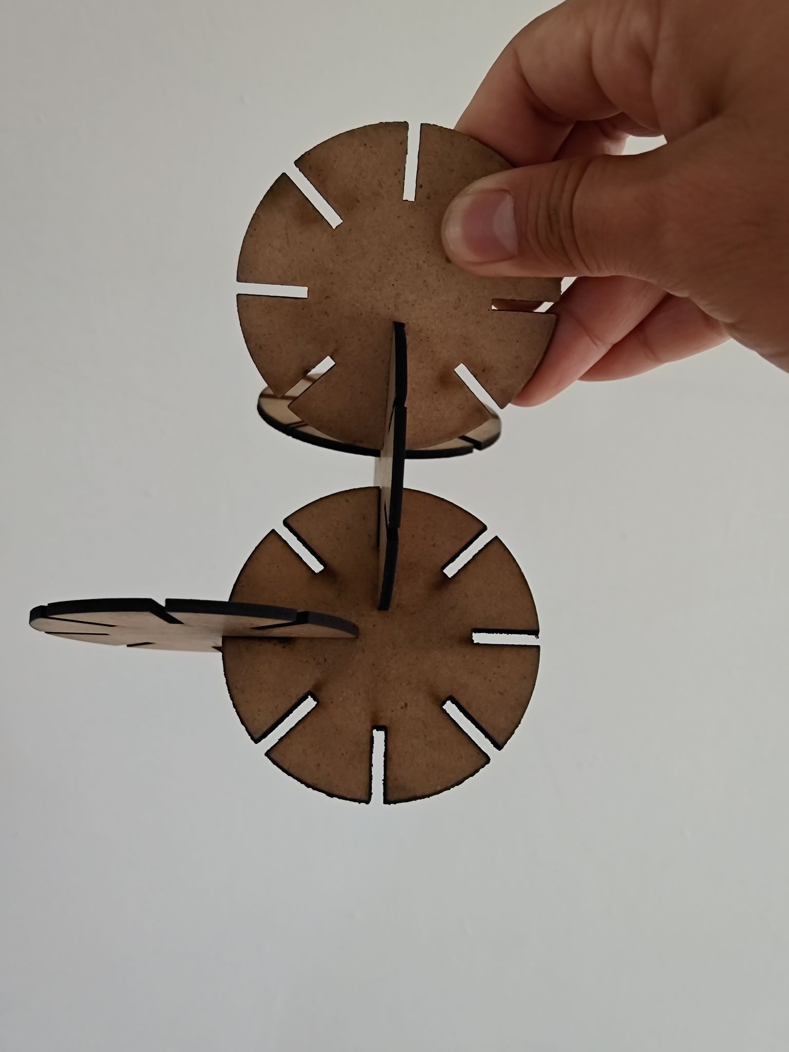
After the adjustments i cut the pieces again.
This time the pieces had the right distance between them, so i can create any modular shape that can stand by it self.
2. Vinyl Cutter
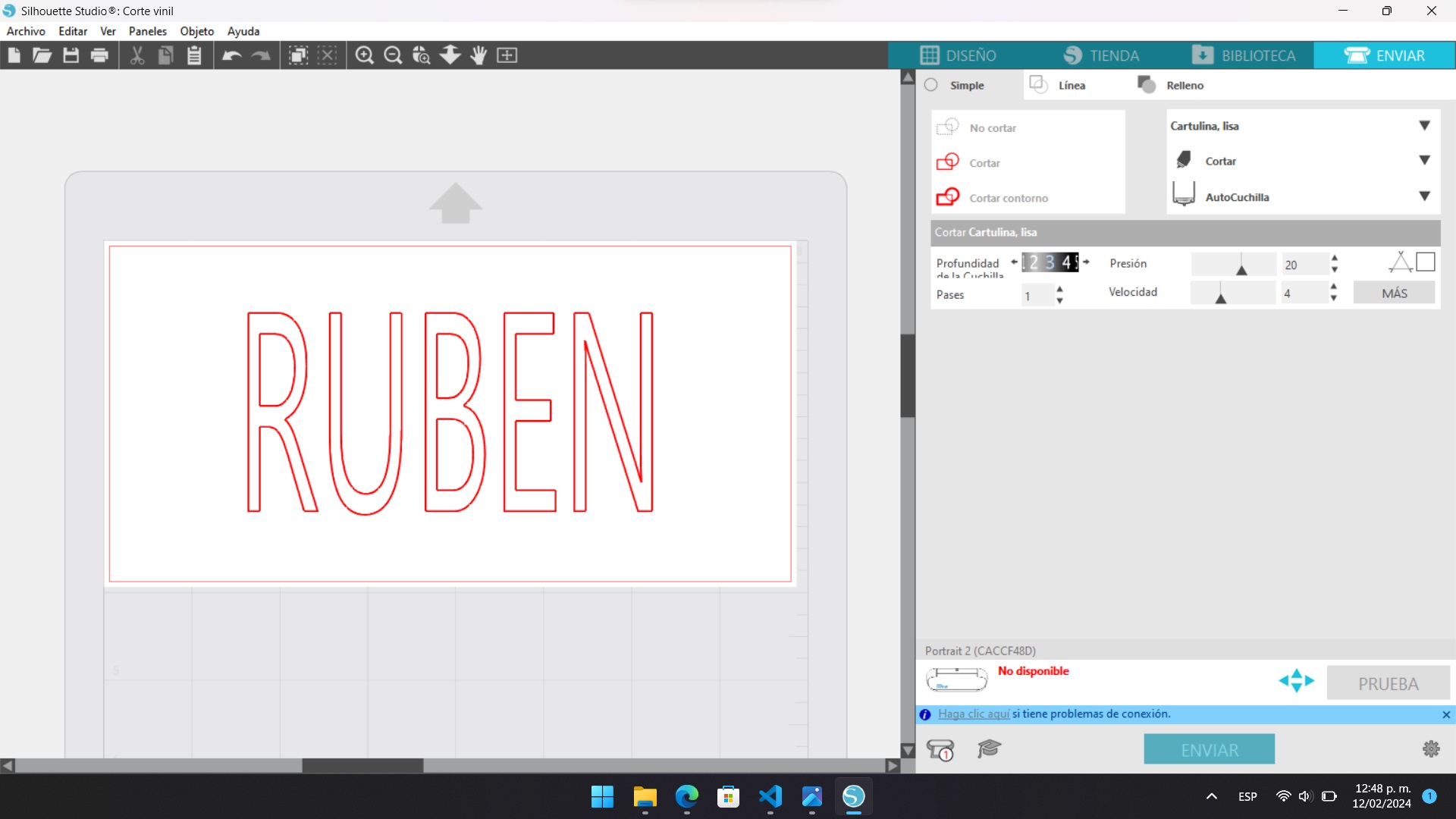
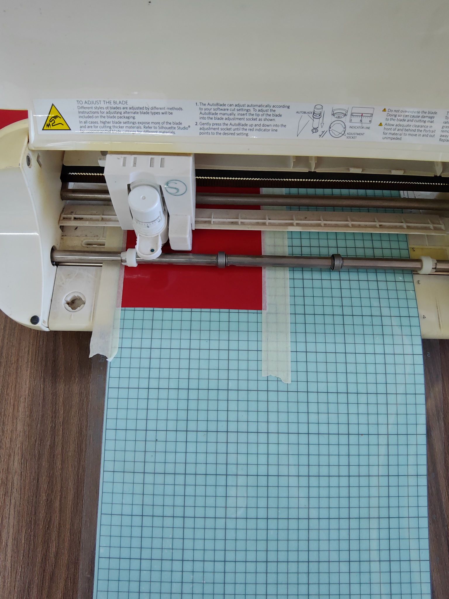
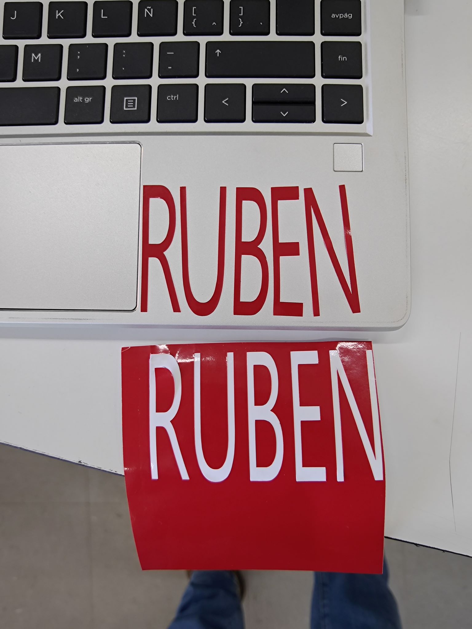
The initial step I took involved creating my name in Inkscape, followed by exporting it to DXF format to seamlessly transfer it to Silhouette Studio. In Silhouette Studio, I configured the essential parameters, such as the size, a deep cut of 3, precision of 20, only 1 pass and a speed of 4. Ensuring the accurate representation and effective realization of my name in the final vinyl cutout.
Photos
Group assignment
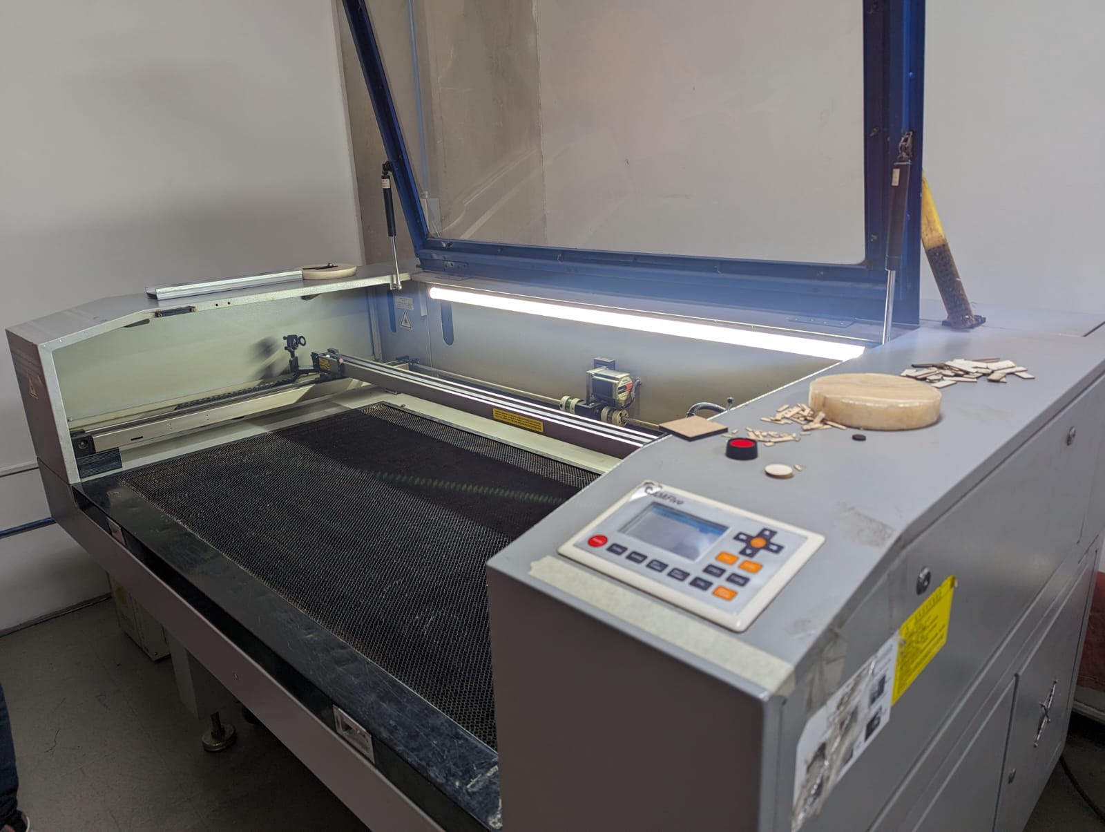
1. Laser Cutters
In Fab Lab Puebla, they use CAM-Five laser cutting machines that leverage CO2 technology to execute precise cutting processes. These advanced machines are equipped with cutting-edge features, allowing for unparalleled precision and efficiency in their laser cutting operations. The utilization of CO2 technology not only ensures a high level of accuracy in the cutting process but also contributes to the overall versatility of the equipment, enabling it to handle a diverse range of materials with finesse.
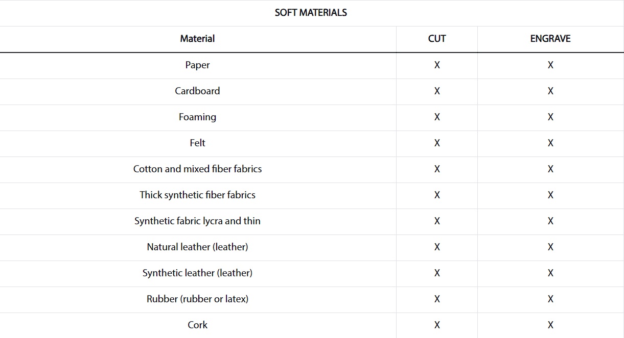
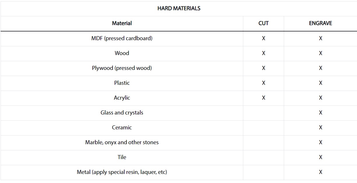
Compatible Material List
3. Power and Speed
For the first test the min power we used was 10% from a 100 Watt laser, and from there we did an incremental increase of 10% until reaching the maximum power of 95% as it's not recommended by the manufacturer to up to 100% power. Similarly, for speed, we started at 15 mm/s and gradually increased it by 5mm/s until reaching a speed of 40 mm/s.
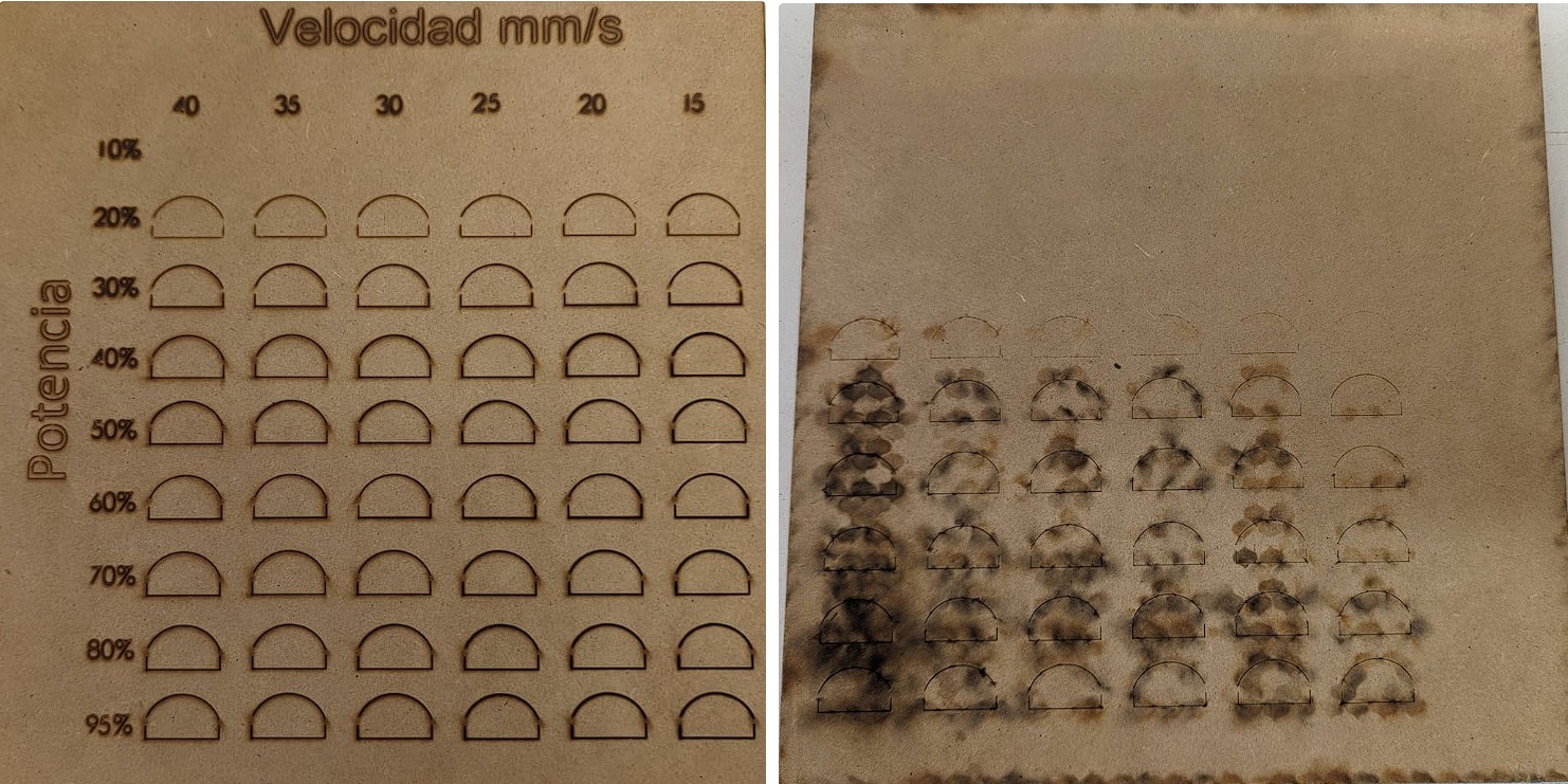
In this test we can observe on the back part of the cut that power percentages from 30% or lower werent able to cut the material, and 10% wasnt even able to engrave it. In 40% the laser barely cut through qith the slowest speed being the only correct cut. All other percentage were able to cut the material however the cleanest ones was 50% with a speed of 40 mm/s, we can also observe that the slower speeds become really burn which means a worst kerf.
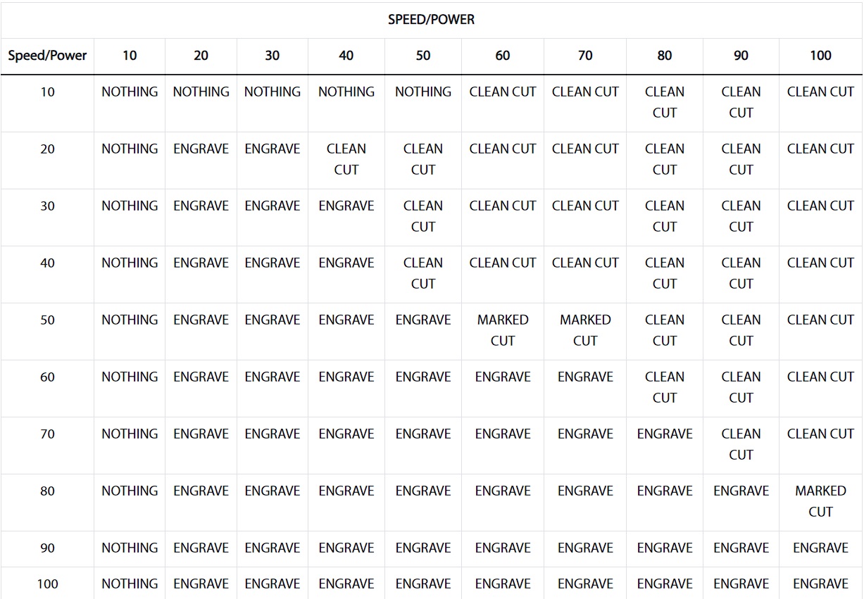
We made a chart to show the results
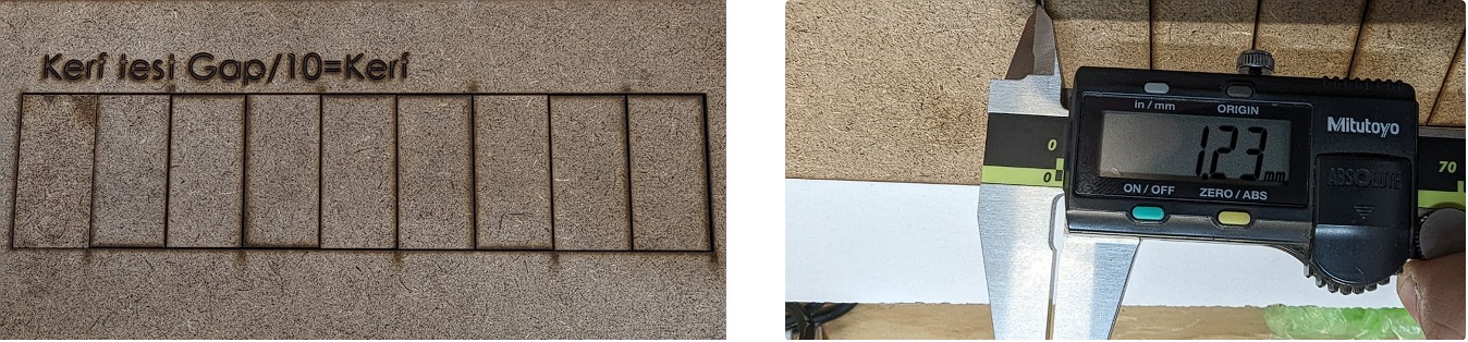
4. Kerf
When a laser cutter cuts a line, it burns away material. Because a laser beam has a certain width, you end up with a part that is slightly smaller than you want, unless you account for this. The kerf of a laser is the amount of material that gets burned away
To figure this out, we cut out a series of rectangles. I tested it using both 3mm MDF and 3mm acrylic. By obtaining the number of lines, the formula becomes easy as I have that number of inner lines that count for a full kerf. By sliding all pieces to one side we create a gap that we are able to measure using a caliper. This means that the kerf can be calculated by dividing the gap by the number of cuts.