Electronics Production
This week's assignment is called: Electronics Production. Which consist in creating my electronic board by soldering, engraving, cutting and programming
Team Practice
Link of our team practice.
Materials
- Weller soldering station - Our Workplace.
- Soldering iron(tin) - To connect the elements to the chip plate
- 1k Resistances - Used to adjust the voltage of the components
- Led Component - The lights for us to program
Getting Started
Once I downloaded the program, VPanel which will help me to engrave my design, using a "ROLAND SMR-20" machine. I downloaded the PNG files that I used in the "Mods" software to kinda translate the information for the machine. With my engraving and cutting files ready, we can finally start this weeks project!

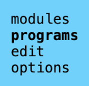
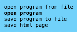
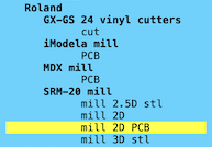
Now on the "mobsproject" page (Link Below) where we can tell the program how we want to cut it and engrave our copper plate, so we can get the file we'll send to the SRM-20 cutter. In the top left corner of the page, we can access the menu, go to: Programs, Open Programs, and I then choose the machine, which was a mill 2D PCB
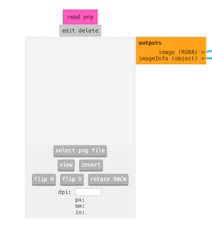
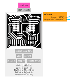
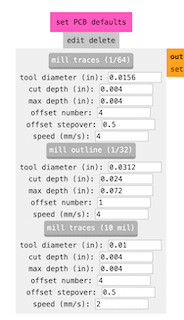
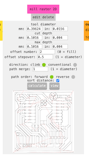
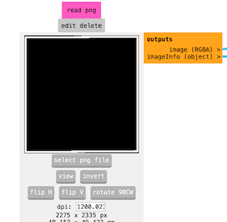
Inside the "read PNG" section, I uploaded the engraving image, once uploaded I needed to adjust some parameters in order to start the machine. In the section "set PCB default" I made sure the mill traces was set to 1/64, then I changed in the mill raster 2D the offset number to 2
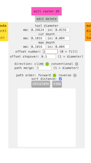
In the Inputs and Outputs section, I turned the switch on and on Mill raster 2D I clicked calculate to create the document I needed for the program, I then downloaded it in the .RML format.
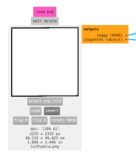
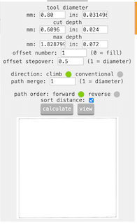
I then did the same thing with the other image, only with a few modifications: Once I added the image, I inverted it to cut only the outline without touching the other file engraving. I also changed the thickness of the piece to 0.8MM, I downloaded it again.
Usign the machine
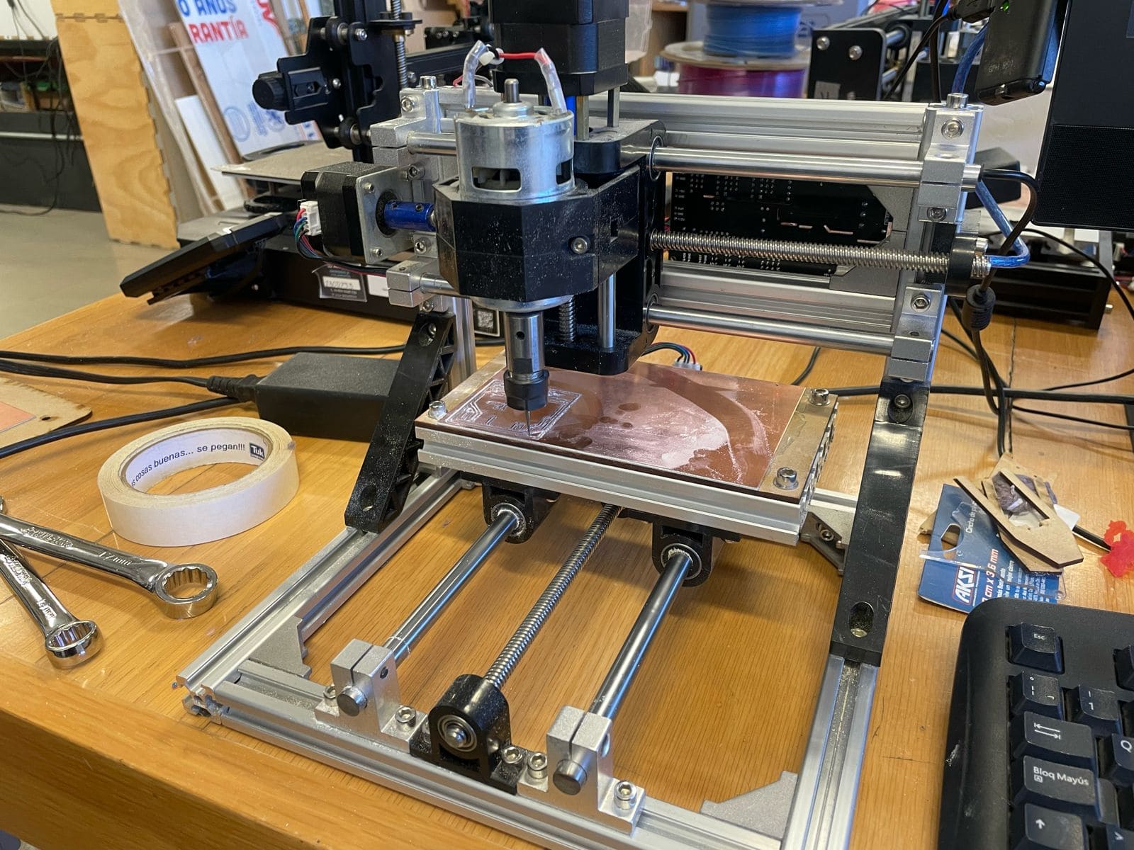
Now we are all done with the setting up of the programs to give the machine, I got my MDF board with the machine's size and attached a recycled copper plate. I then secured it with screws to the machine's table, so I could open the program of VPanel for SMR-20. Now, I can open the RML File for engraving and positioned the machine using the keyboard arrows and shift/control so it could be in the bottom-left corner of where I wanted my piece, once in place I marked the X and Y position as the origin. Once it was in place, we could "Plug" the machine and let it do its magic.
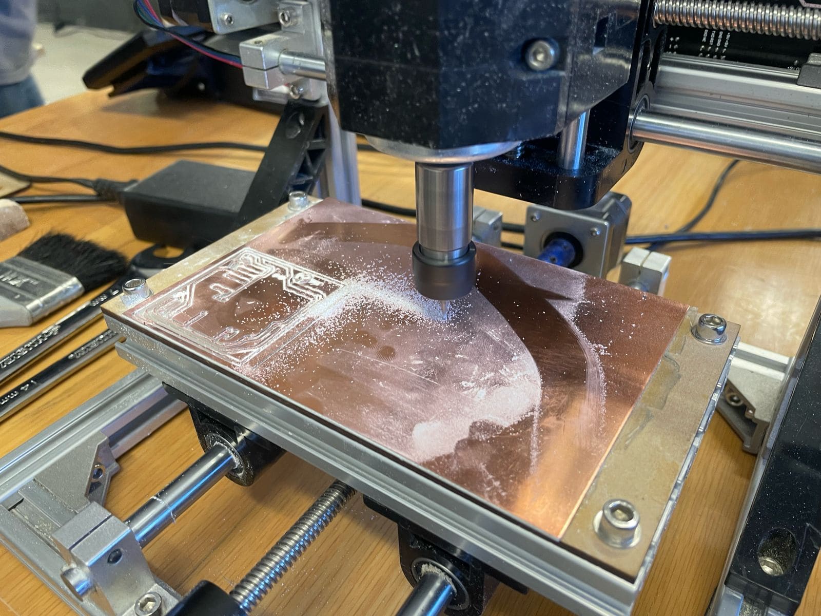
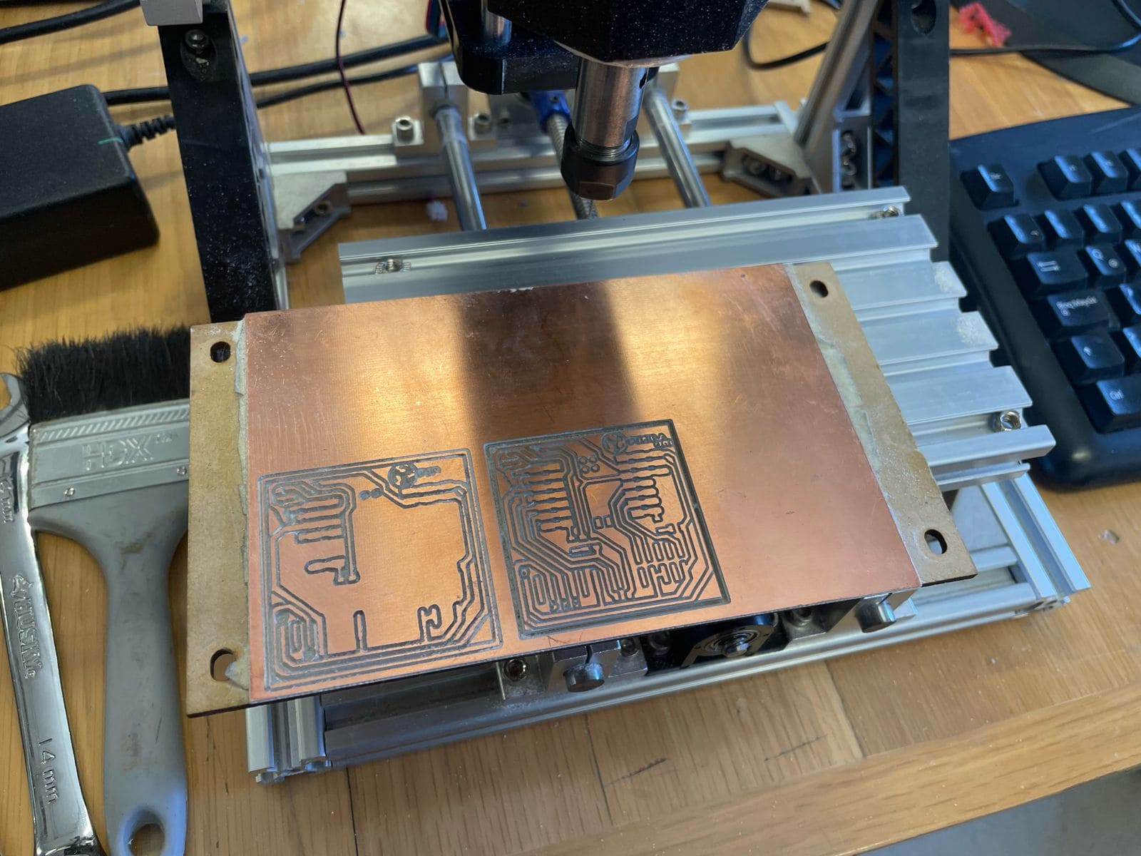
After approximately half an hour, the engraving was done. I then changed the tip of the machine so it could be better for the cutting part, I used two wrenches and took out the piece, inserted the new one and pressed again to set in place. I then opened the other file, set the machine to the origin position and "Plugged" again. I used a handheld vacuum to clean all the dust the machine had generated, brushed the plate and used a compressed air tube to have a completely dust free copper plate.
Board soldering
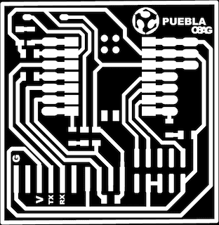
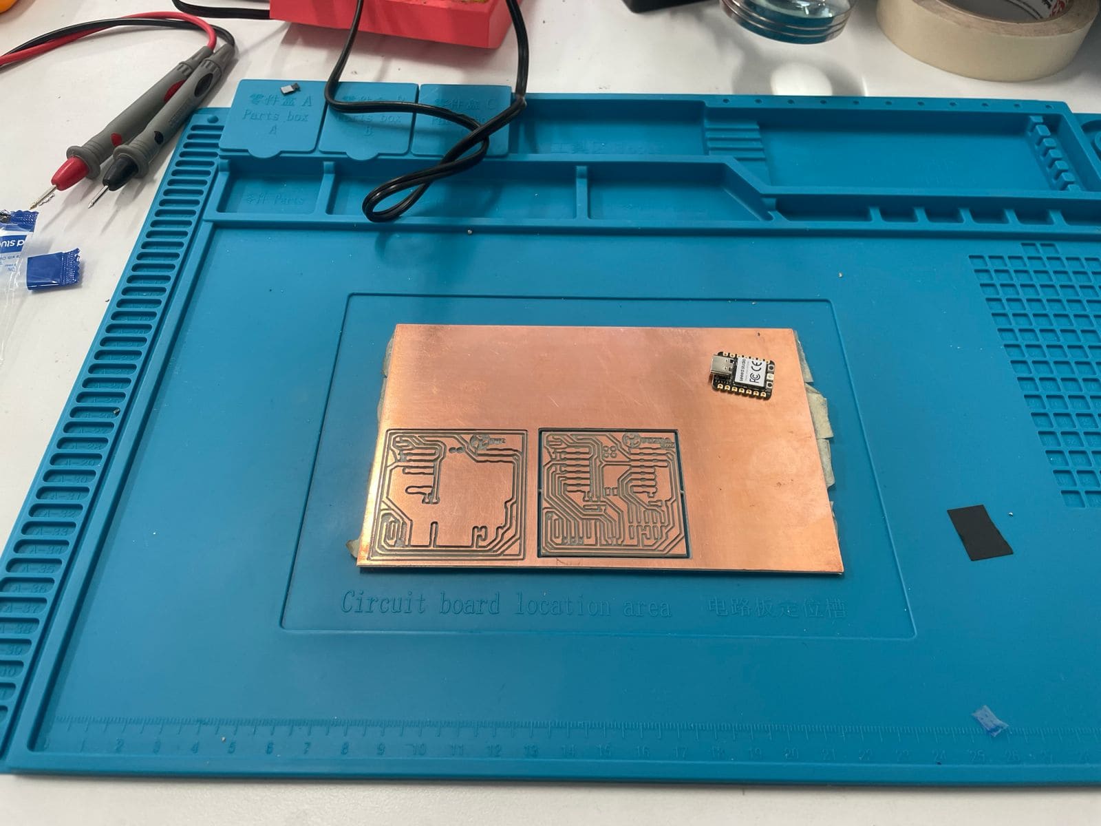
Now we are ready to start soldering, first I practiced with some dots in the upper-left corner of the plate, once I was comfortable with the results I moved to the real deal. The components required for this project consist of: 1 Xiao, 1 Push Button, 7 Resistances and 3 LED Lights. I started taping the Xiao on to the plate, so I could solder without it moving around. I then used a soldering iron and solder, and started with the whole Xiao perimeter.
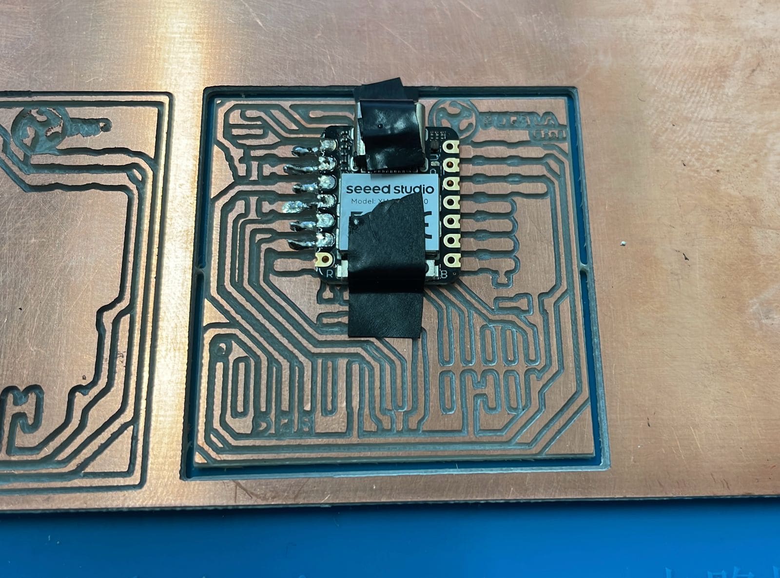
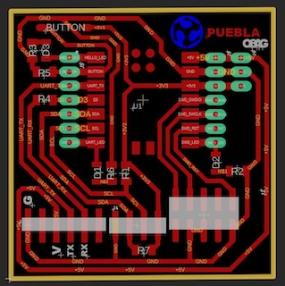
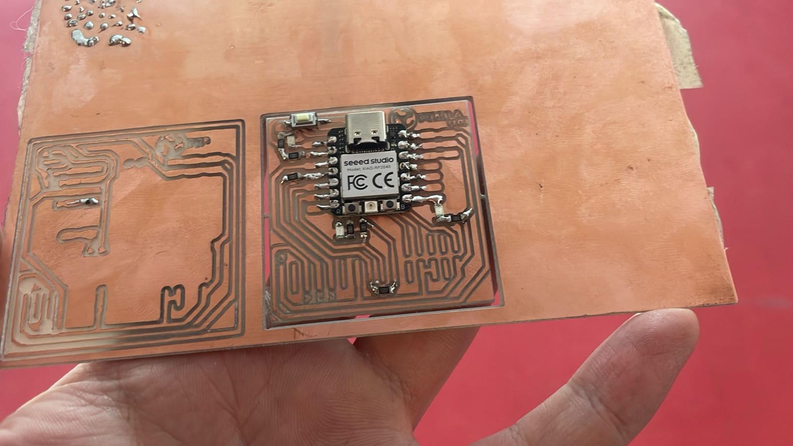
Based on the provided diagram, I started soldering the resistances, having in consideration they have no right or wrong side, I just had to solder them where the "R" are. Once in place, it was time for the LED lights, this did have a side, I had to solder them with the green line in them looking to the resistance I already placed. Finally, the button, placed in the top-left corner of the piece, unfortunately, there were no available pins, so I will have to wait until there's more that I can use. With that taken into consideration, here's my finished piece, for now.
Board programming
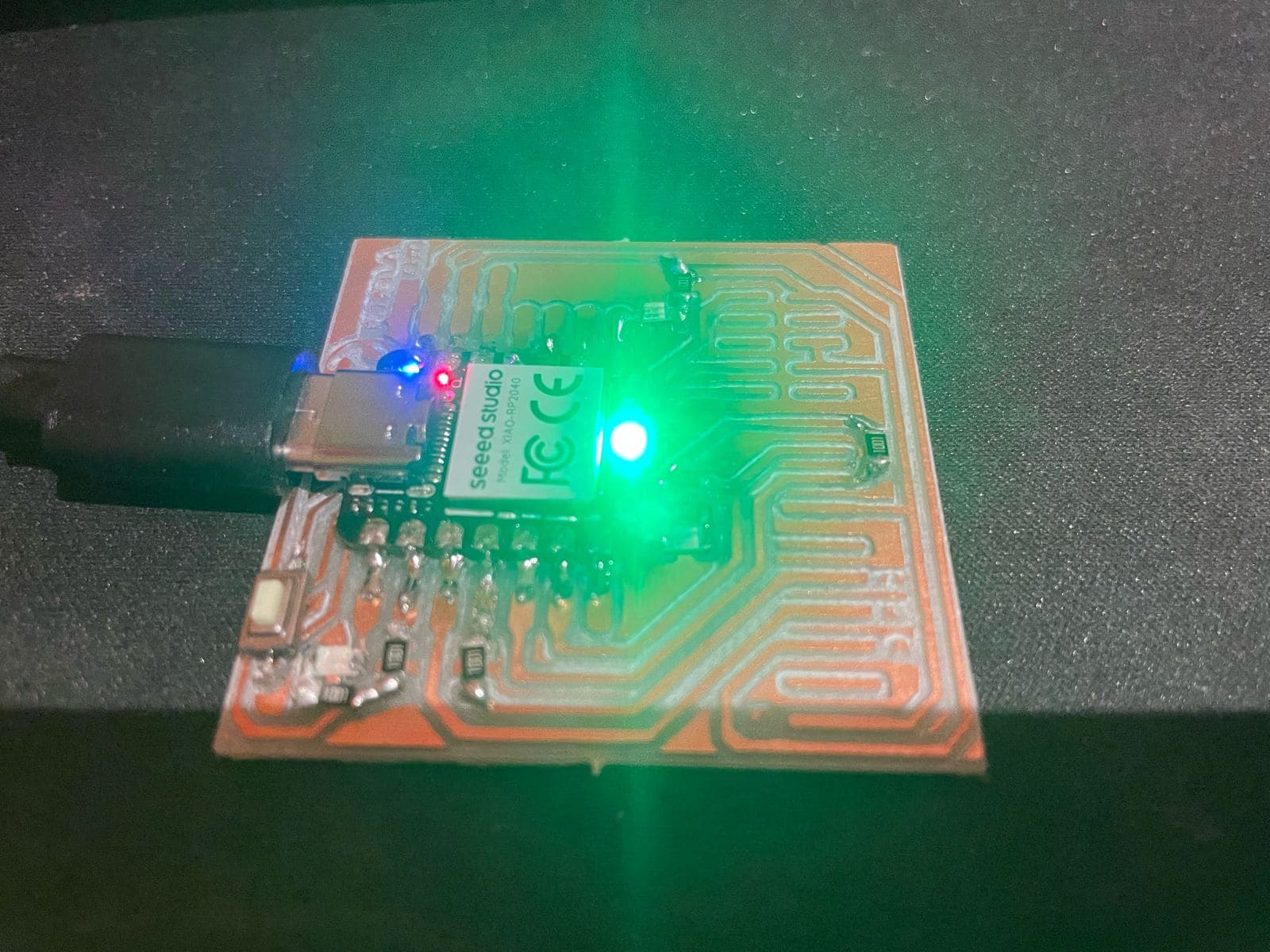
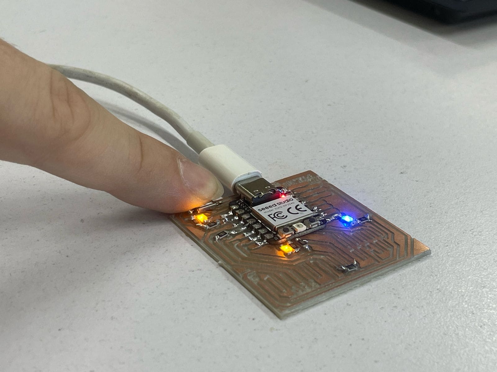
Before trying to program the board, we need to see if it works by giving it some energy:

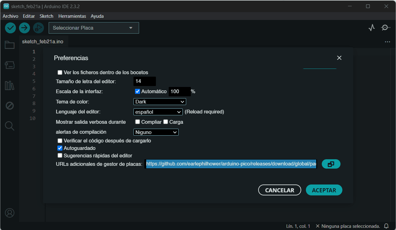
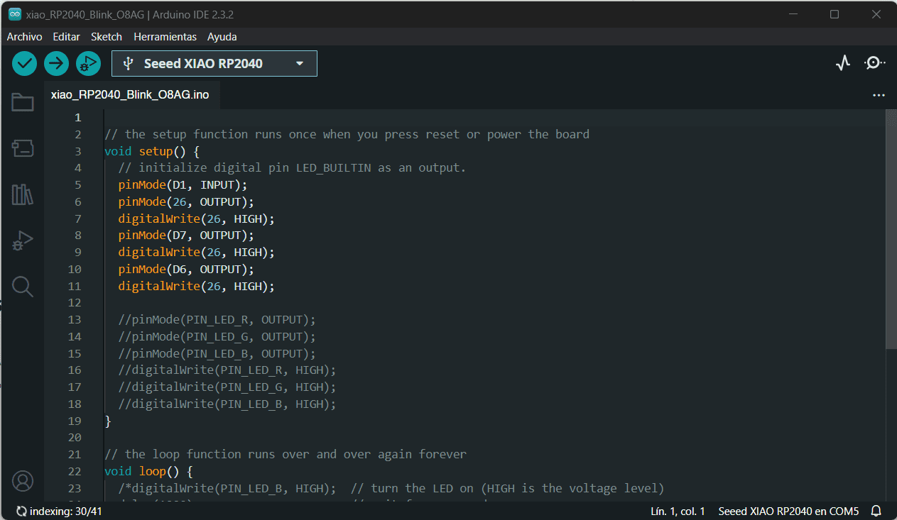
Once certain it works correctly, I needed to download the program ARDUINO IDE, once downloaded, I installed a board manager for the XIAO RP2040, I looked online and copied the link. (Link Below). I then returned to Arduino and went to: Files → Preferences → Configuration, scrolled down and in the Additional URLs Section, pasted the link and clicked "OK"
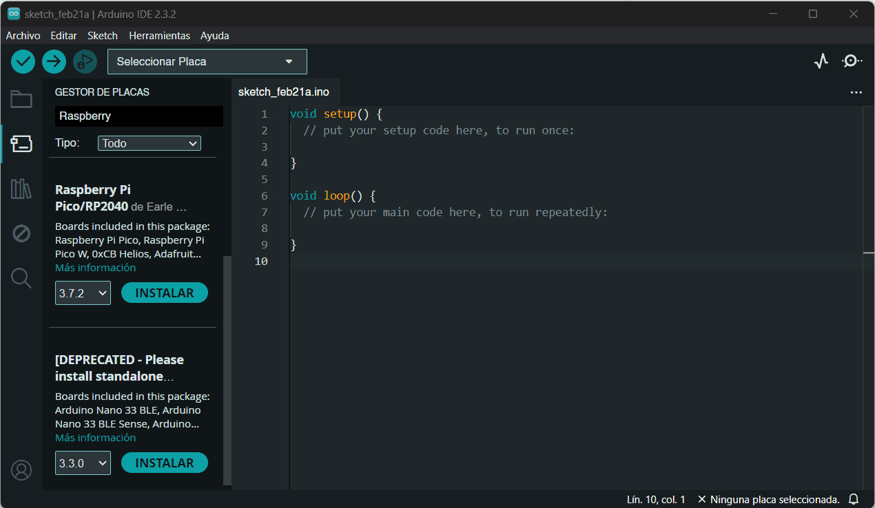
Now, I opened the board manager and typed "Raspberry Pi" in the search bar, so I could install the RP2040 version. I then downloaded the test code that our teachers in Fab Lab Puebla sent us, I opened the file and selected the document, once there, I connected the board to my computer and went to: Tools → Board → Raspberry Pi Pico → RP2040 → Seed Xiao RP2040, and selected it.
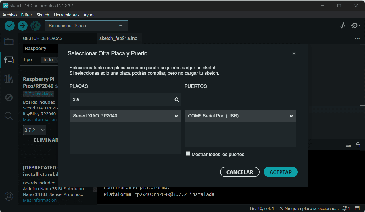
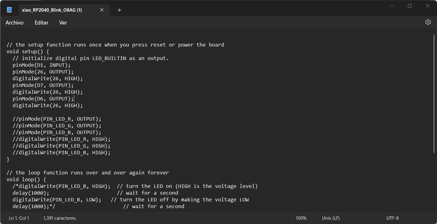
I then selected my port in: Tools → Port → dev → cu.usbmodem101. Furthermore, I then selected the Verify icon, once the message said "Successful compilation" we were done! I just needed to upload it using the upload code icon!
This was a really fun week! I learned a lot of things I didn't know about programming and soldering. Once installed the code, the board is now blinking! And if I press the button, a new LED starts to light up!