Creating my First Fusion 360 Model
Now that I have a better understanding of my project, and my web side is up and running correctly (so far), for the second week we need to learn how to use Fusion 360, it is necessary for us to learn it in order for us to have a more physical idea of what it what we are doing. That's why for this week I wanted to model one of the modular pieces in my hydroponic tower garden.
2D Software
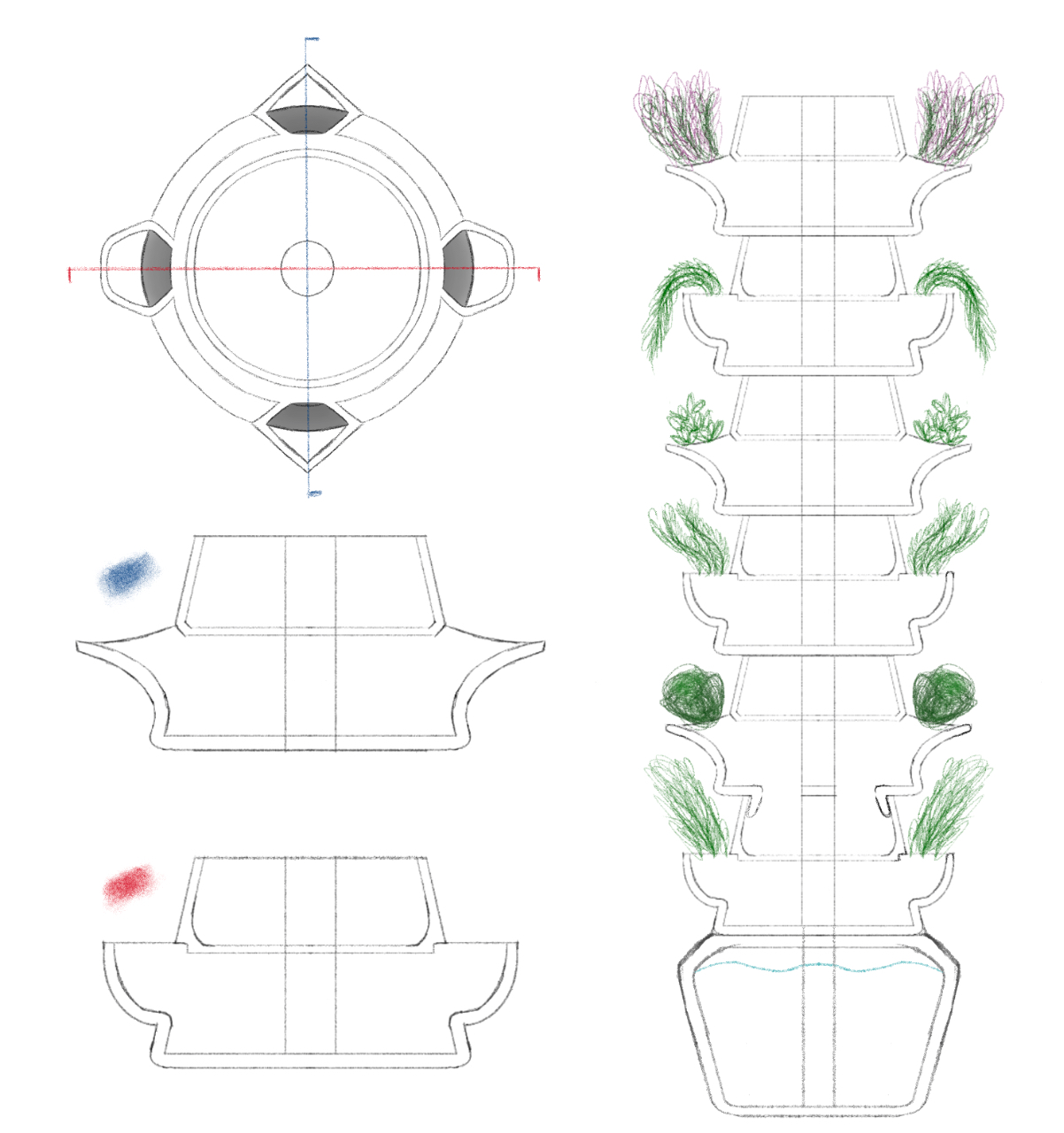
I first needed to create a sketch of what I wanted to model, in this case, one of the modular pieces of my final project. In procreate, I drew a first sketch of what my final project could be in order to have a better understanding of the individual pieces.
The Shape
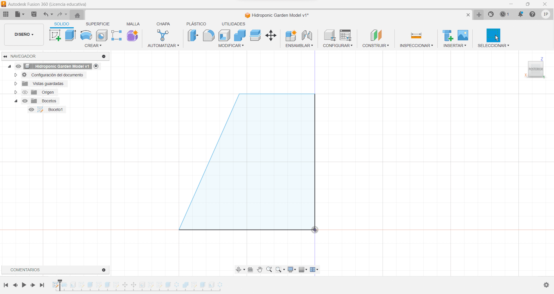
First, we create a new sketch in any axis, y opted for the x one. Now that we are in the sketch menu, we can create a vertical line of 50 mm starting from the 0 point, and another horizontal line with the same measurements, now, for the shape I'm trying to achieve I made another line starting from the end of the vertical line to the x-axis of 37.5 mm, have in consideration that this is my first model for my project, changes and sizes will be made. Once we have those 3 lines, we can connect them.
The Tornado
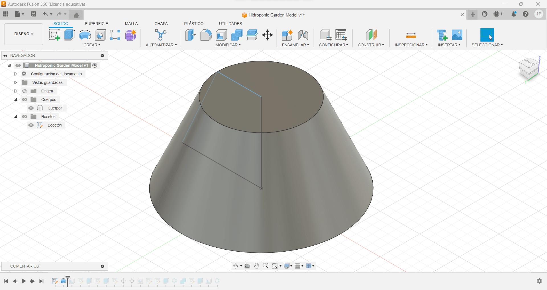
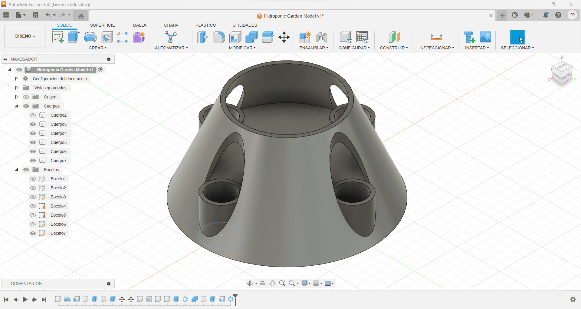
Now with the sketch done, we can use the tool Revolve, and using the vertical line as reference axis, this basically makes the shape spin on itself with the vertical line stuck in place, we now have our shape!
The Umbrella
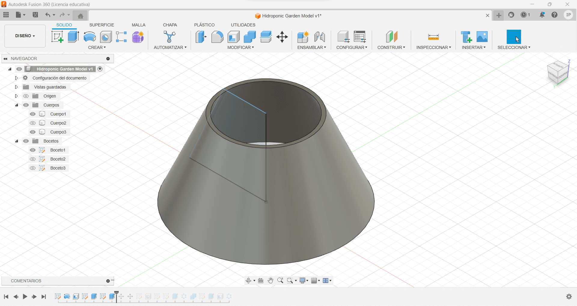
We went from a 2D sketch to a full 3D figure, that was amazing! Now let's make a hole in it. The pieces need to be hollow in order to stack one on top of the other, so we are going to use the tool Emptying, leaving a thickness of 2 mm
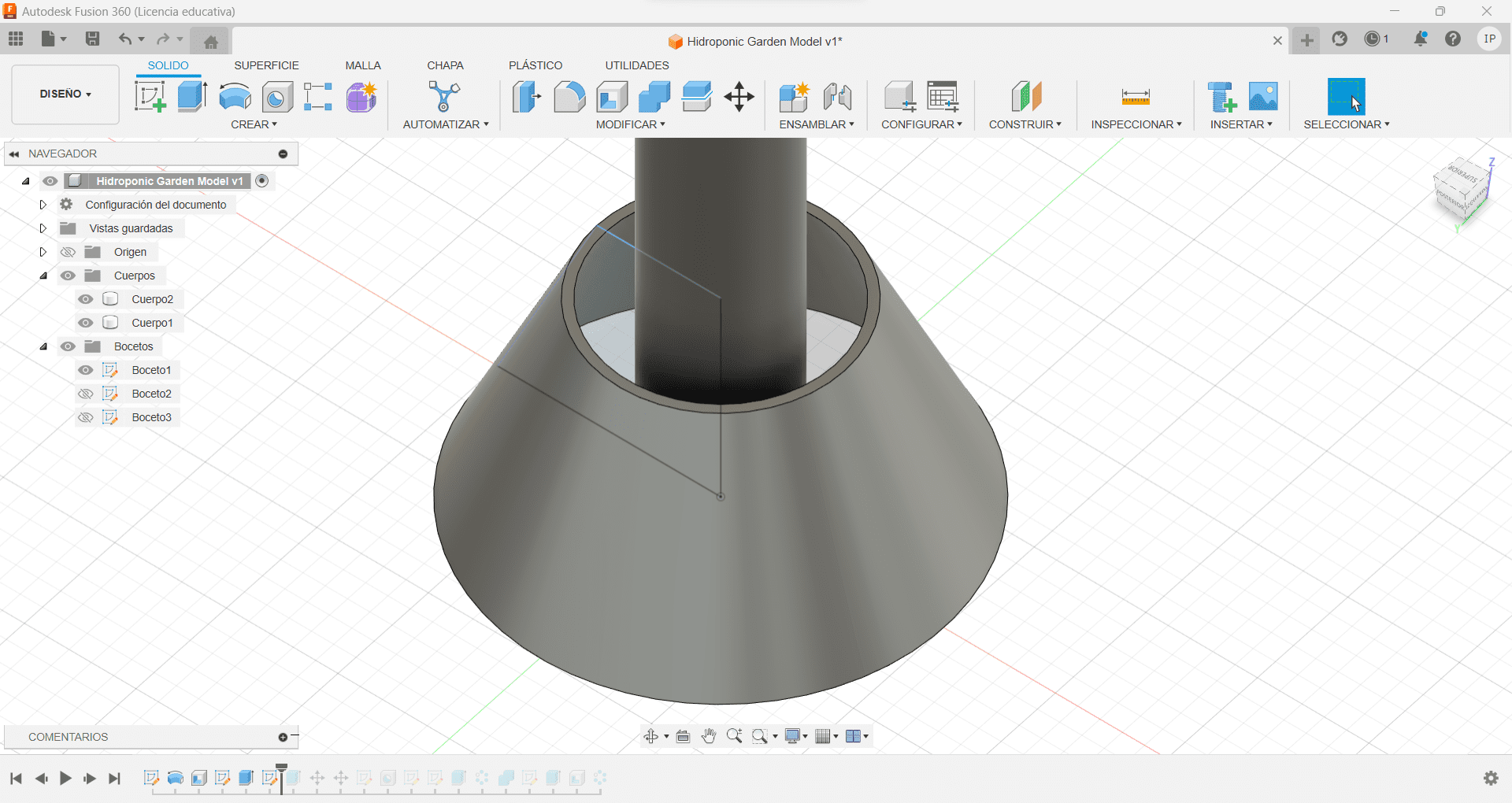
The Spear
We now need to create a Central tube, why? Because we need to have in consideration the central structure, where water is going to pump from the base into the top of the structure, so I made a tube with 30 mm wide in the middle if the shape.
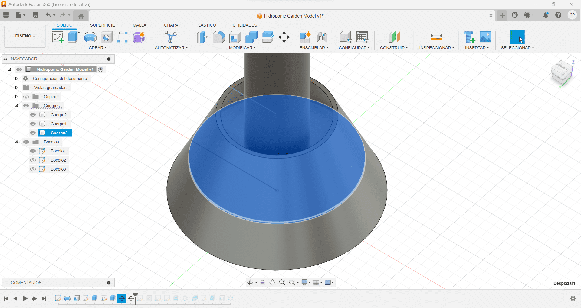
The Plate
Having the tube in the middle, we now generate a sort of "Plate" by creating another sketch with a circle, but now with a length of 75 mm in the same place, we then extrude it to be 2 mm wide, once we have this shape we can move it to the middle of the figure, so they collide with each other. Now that the plate is in place, we can use the tool Merge to create a single 3D model between the two of our figures, this shape should be colliding with the central tube!
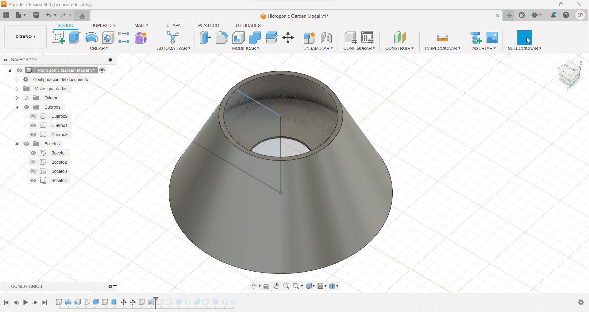
The Umbrella - Part 2
We can now use the tube we have in the middle to create a Bolean Difference, so we can have the hole already in the figure, giving the piece support over the middle tube
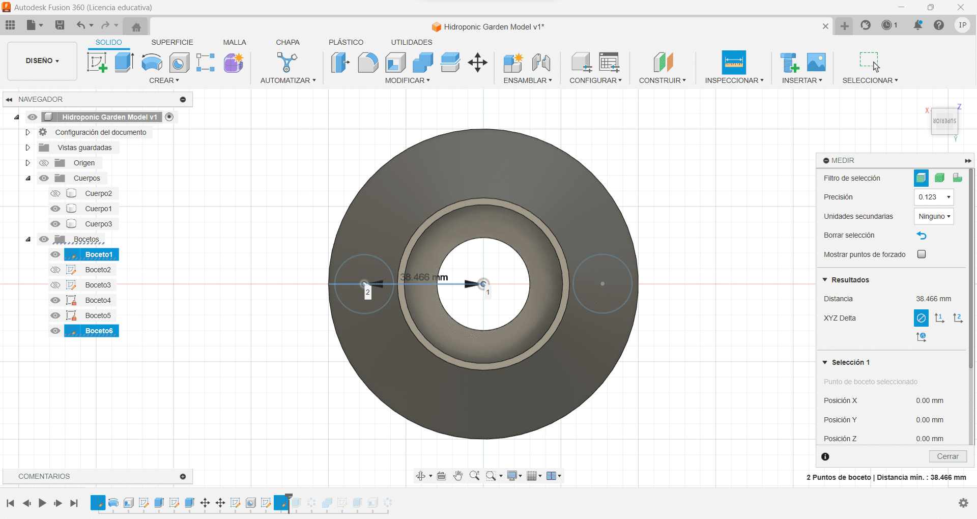
The Projection
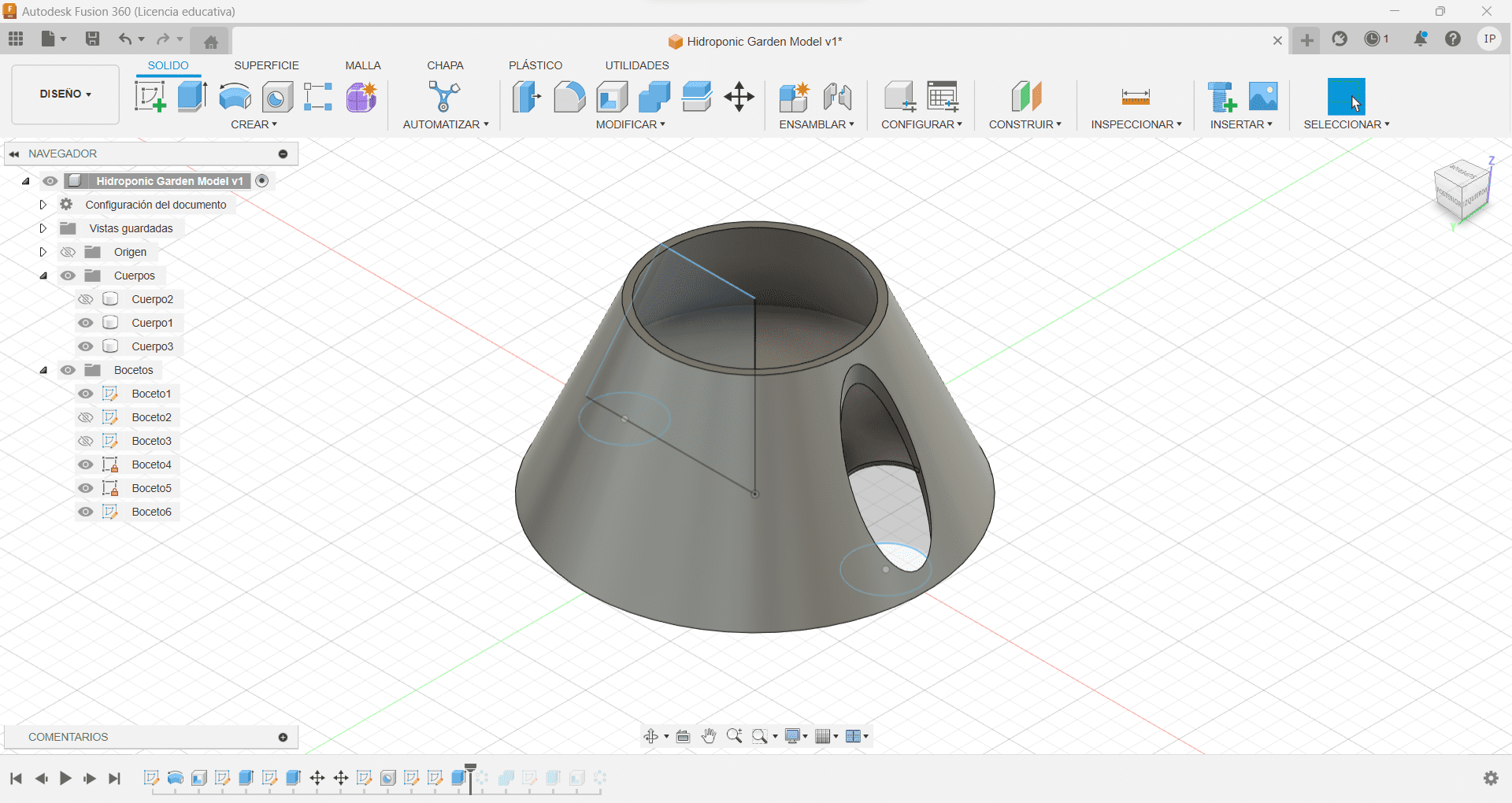
Once we have the base figure completed, we can work on the details, for that, I set the view to top, so I can create a circle with the length shown on the image, which is the middle line of the figure, using that reference, I then made another smaller circle, so I can project it and remove the highlighted part.
The Collision
With the circle in place, I can now use it to extrude and remove the colliding part, so we are now left with the hole where the plant is going to go (remember this is just the first phase of the modeling process, future changes will be made which can compromise the shapes we are doing at this moment).
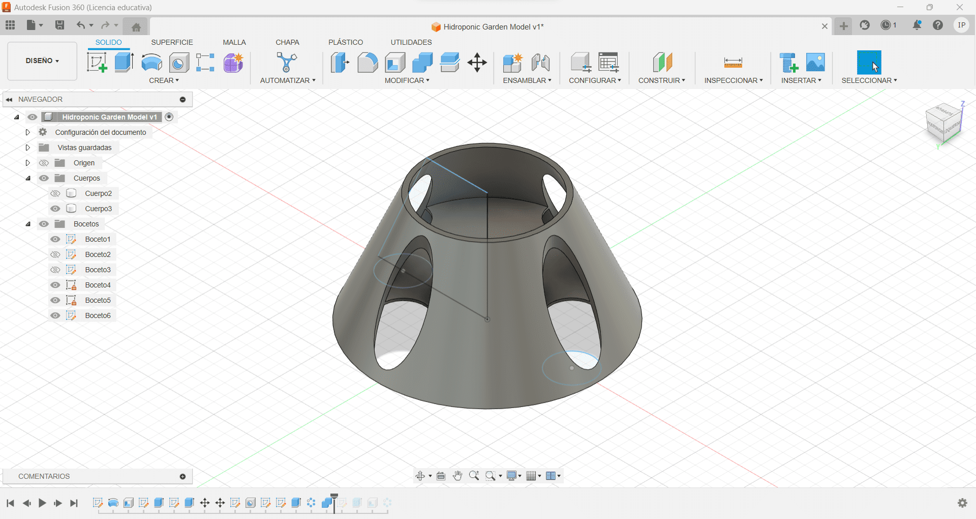
The Pattern
Now with the hole made, I can create a circular pattern of the extrusion using the middle point as an axis and have other 3 holes in the figure symmetrically aligned with each other. If you look close enough, you can see I'm not only doing the holes in the exterior, I'm also projecting it in the "plate" we created, so we can have a place for the pot.
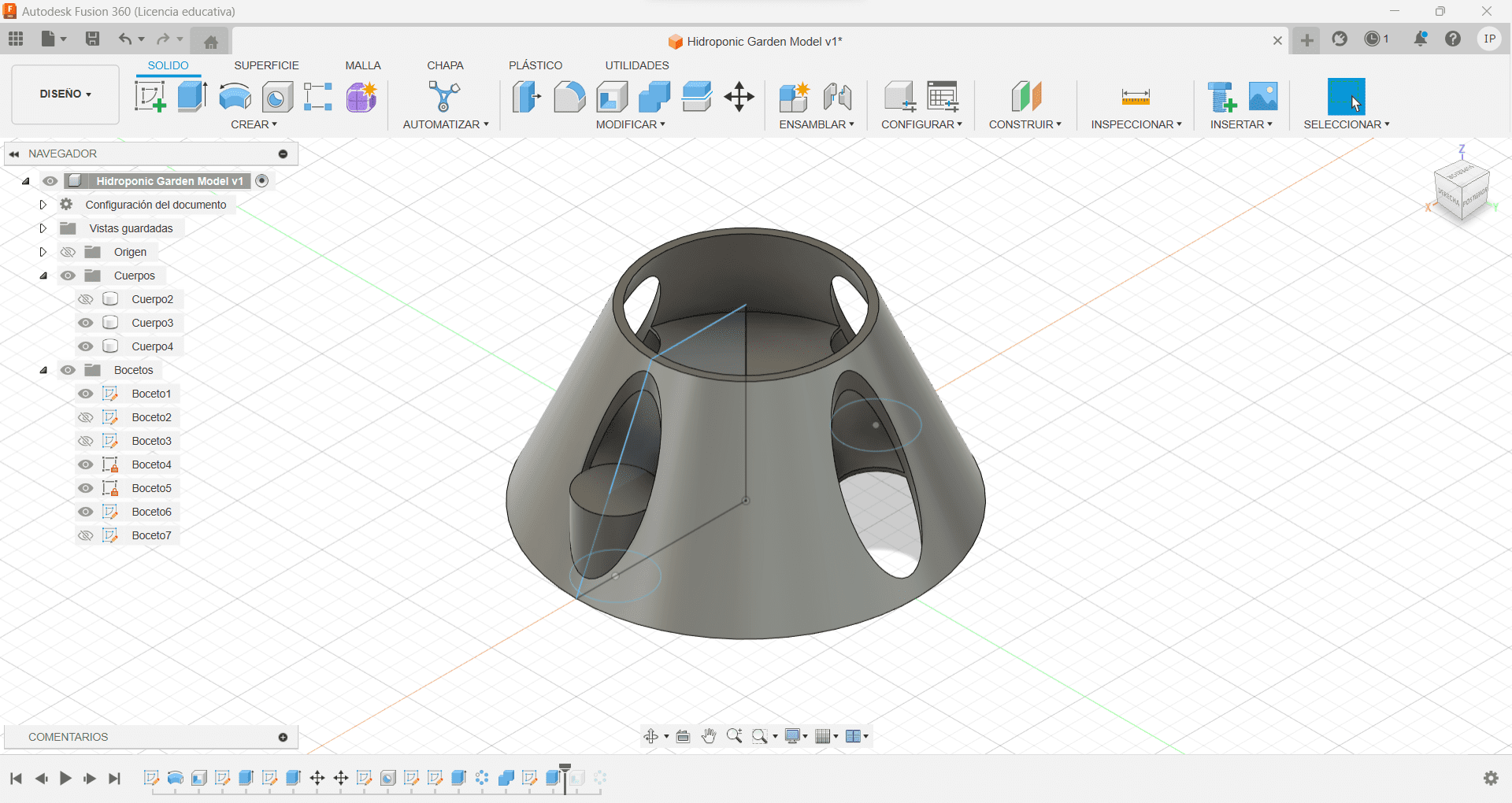
The Pot
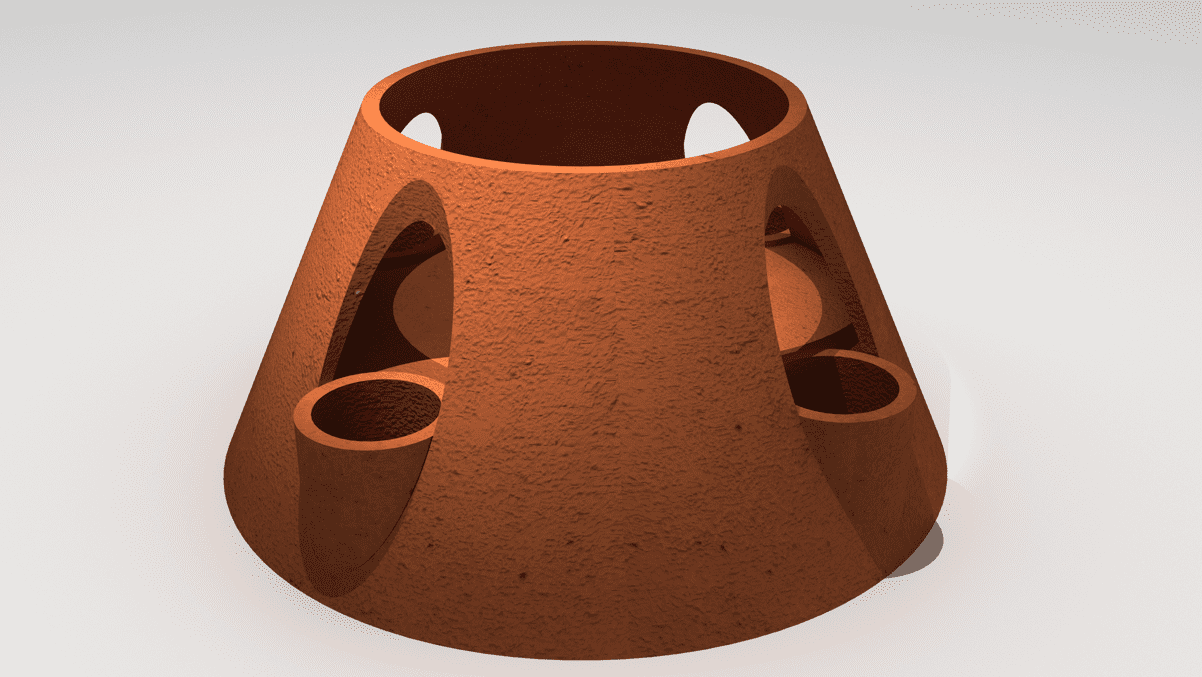
Using that same circle as a base, I created a cylinder that is as long as the middle of the hole we then created, we can now hollow the piece for the soil to be.
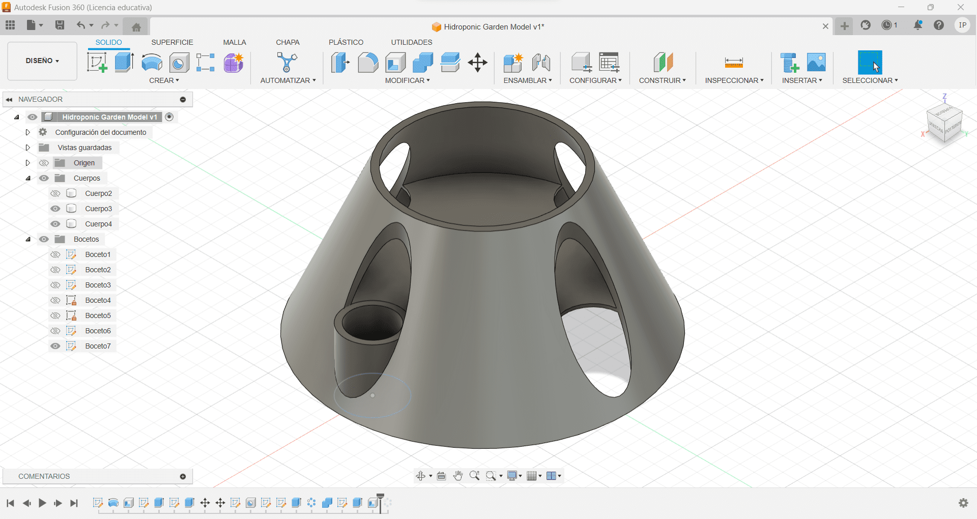
The Pattern - Part 2
Once we have the pot, we can do the same thing we did for the hole and create a circular pattern using the middle point as an axis, creating a pot in each hole, and we are done!
Testing Different Softwares
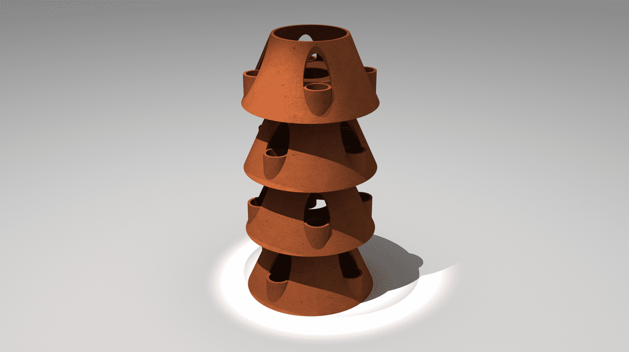
Part of this week's assignment was to test and do some sketches in different software programs, 2D and 3D, so I tried to do some renders in Rhino 7, I personally already knew how to use it, so I simply copied and pasted the file in Rhino just to add some materials, then I rendered the project, leading to these results:
How they work
Working with these two 3D software programs, I can see myself inclined in using Fusion more often, this mostly for the user-friendly display and tools. The accuracy of the measurements makes it easier to work, whoever I still love the rendering process of Rhino, since it creates a more organic feeling.
Exploring 2D Software (again)
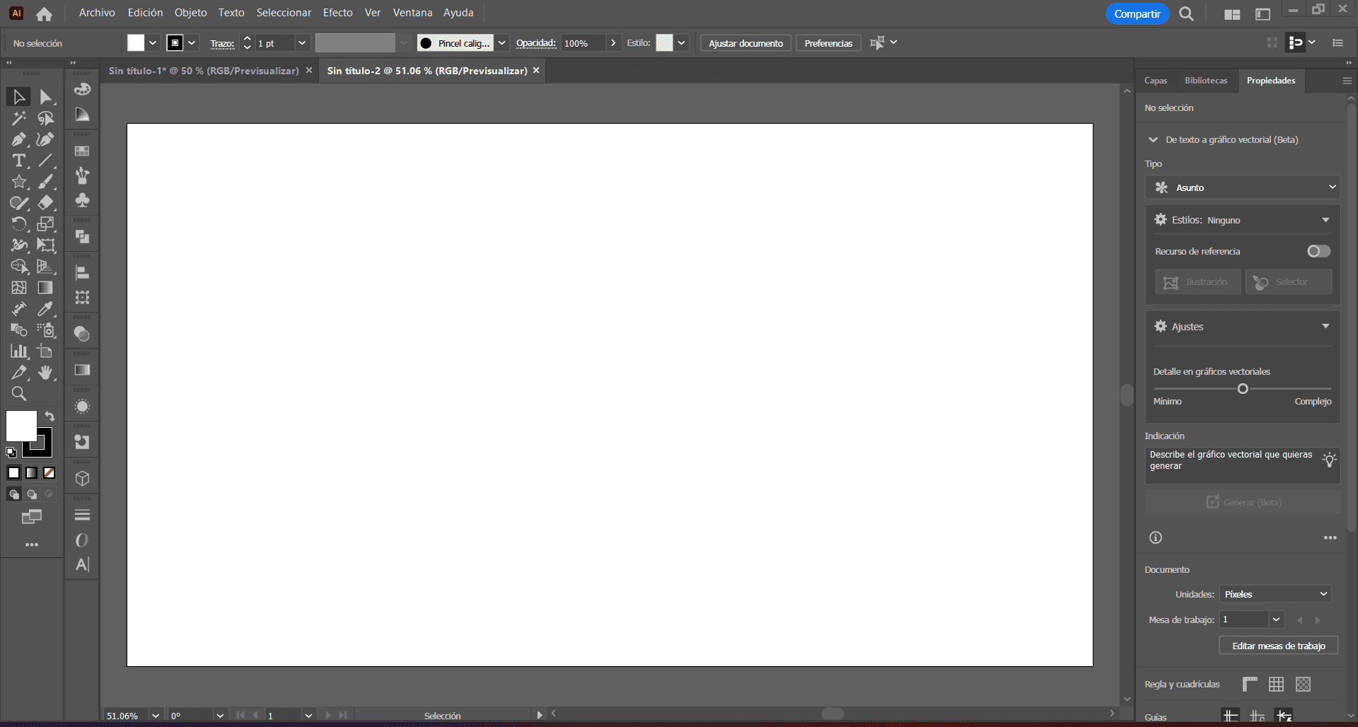
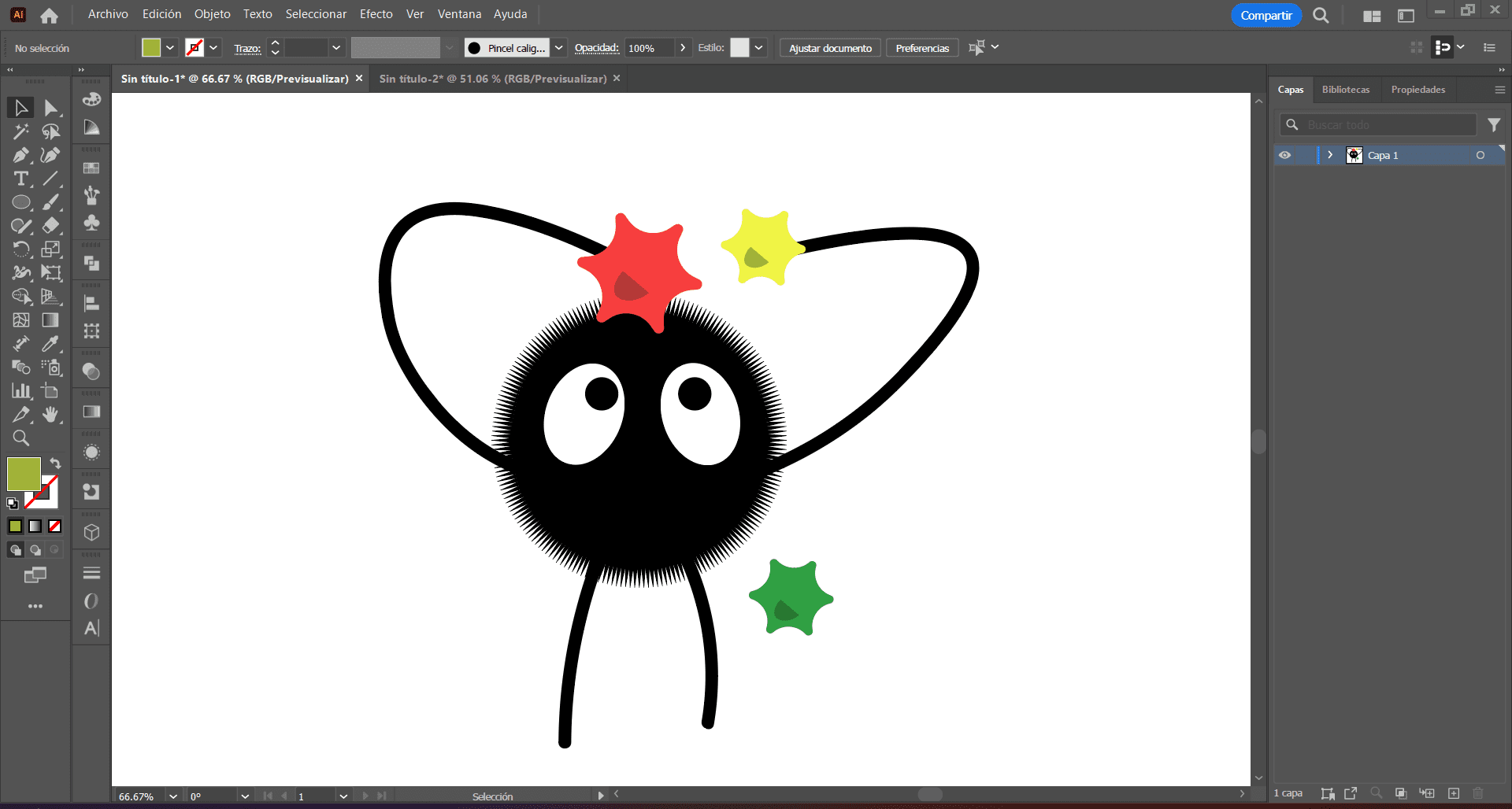
I decided to use Illustrator for and easier practice, I wanted to do an iconic character from one of my favorite movies called: Susuwatari! I first start a new blank workspace about the size of the screen.

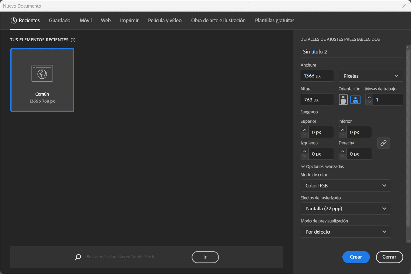
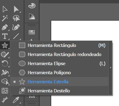
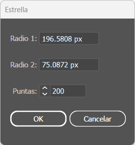
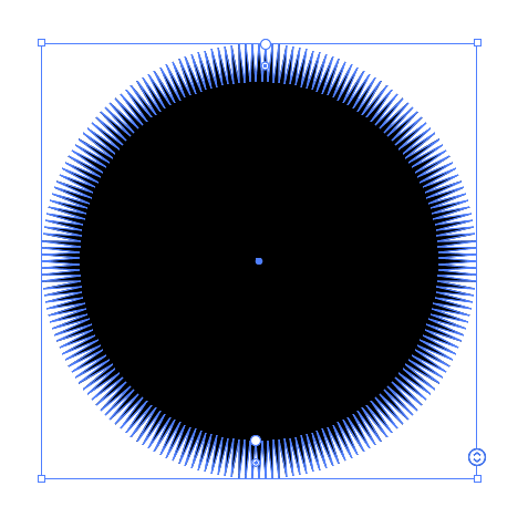
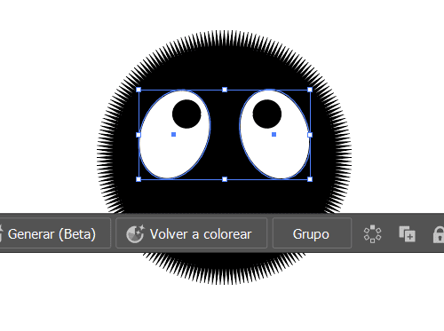
Now that we are here we can start by using the star tool, by right-clicking the shape tool and selecting the star symbol, now we just have to click inside the workspace and the star shape window will appear. Here, I can create a 200 sides star for the fuzzy look we are looking for, and move the white circles in the shape to resize and adjust.
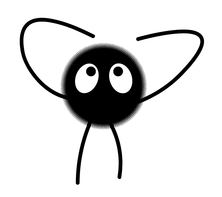
We can then use the same shape tool but selecting the Eclipse tool for the eyes. And use the curve tool for the arms and legs, I'm using a size 10 line with rounded borders. I can then create a 6 sides star and add a little shadow inside. We are now done!