Week 11 Molding and casting
🟡👻 PacMan Mold 🟡👻

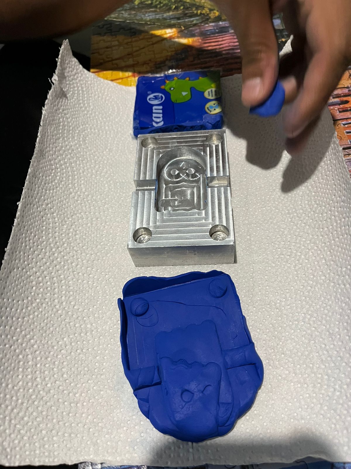
This week, I made a mold, and honestly, I had a lot of fun. I had the opportunity to use my university's HAAS machine to create the mold from a piece of aluminum measuring 90 mm x 60 mm and 23.4 mm in height.
I decided to draw a Pac-Man, with my original idea being to make a keychain from the final piece. Here’s the link to the group week in my Fab Lab, where we learned about the datasheets of the silicone we were going to use and the safety rules. This helped us get an idea of the quantities and percentages we needed to use. Here
Designing my 3D mold

For this process, I designed the 3D model in CATIA because the software offers CAM simulation, allowing me to generate the G-code needed for the HAAS machine.
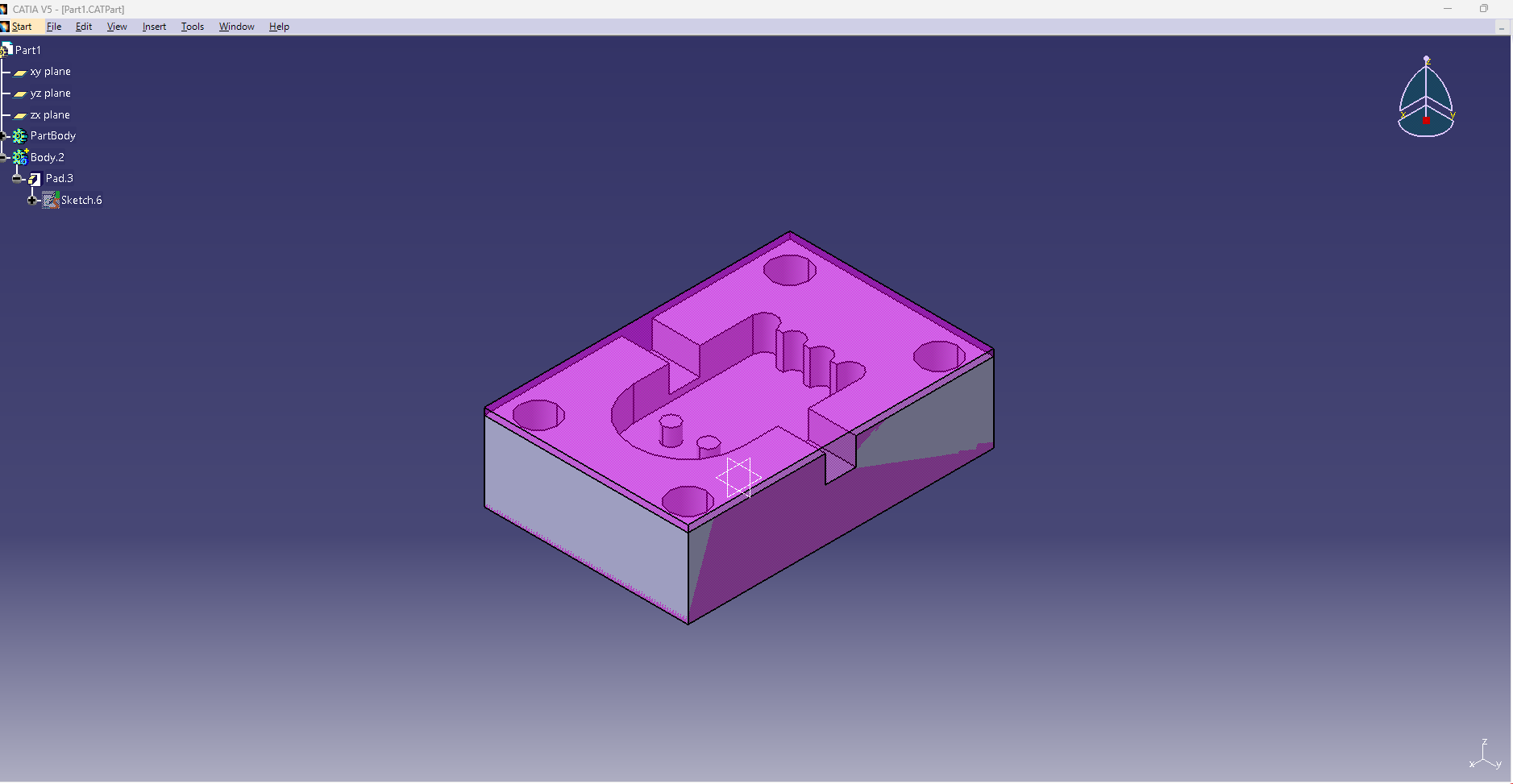
To create this mold, I measured my aluminum block accurately (120 mm x 85 mm x 60 mm) and reduced its height by 5 mm from the top. I then began sketching my Pac-Man design.
I added small T-shaped features at the edges, intending to use them later to attach a ring for the keychain if needed. The process involves first designing the part I need in a CATPart and then overlaying it onto the aluminum block dimensions. I generated a CATProcess, where I programmed the Facing and Prismatic Roughing operations to simulate how the HAAS machine would shape the final piece.

Below, I will walk you through the steps for generating the G-code and exporting it to the HAAS. I’ve also included a more detailed guide on setting the parameters for G-code and machining.


TOOL PARAMETERS :
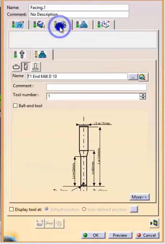
Exporting G-code


Simultation of CAM PROCESS, this simulation help you if you want to have a look of the future part.

HAAS
the setup for the X, Y, and Z zero points. These indicate where the tool tip starts on the aluminum block. Once the tool position is recognized, the lubrication system is activated, and the spindle is turned on, running at the correct speed. Since it’s an aluminum part, a special lubricant is required to prevent tool breakage due to the high spindle speed.


Video
Next, you’ll see a simulation of the HAAS operation. The guide below provides detailed instructions for uploading the G-code file and starting the program. Finally, I’ll show the end result of my mold.


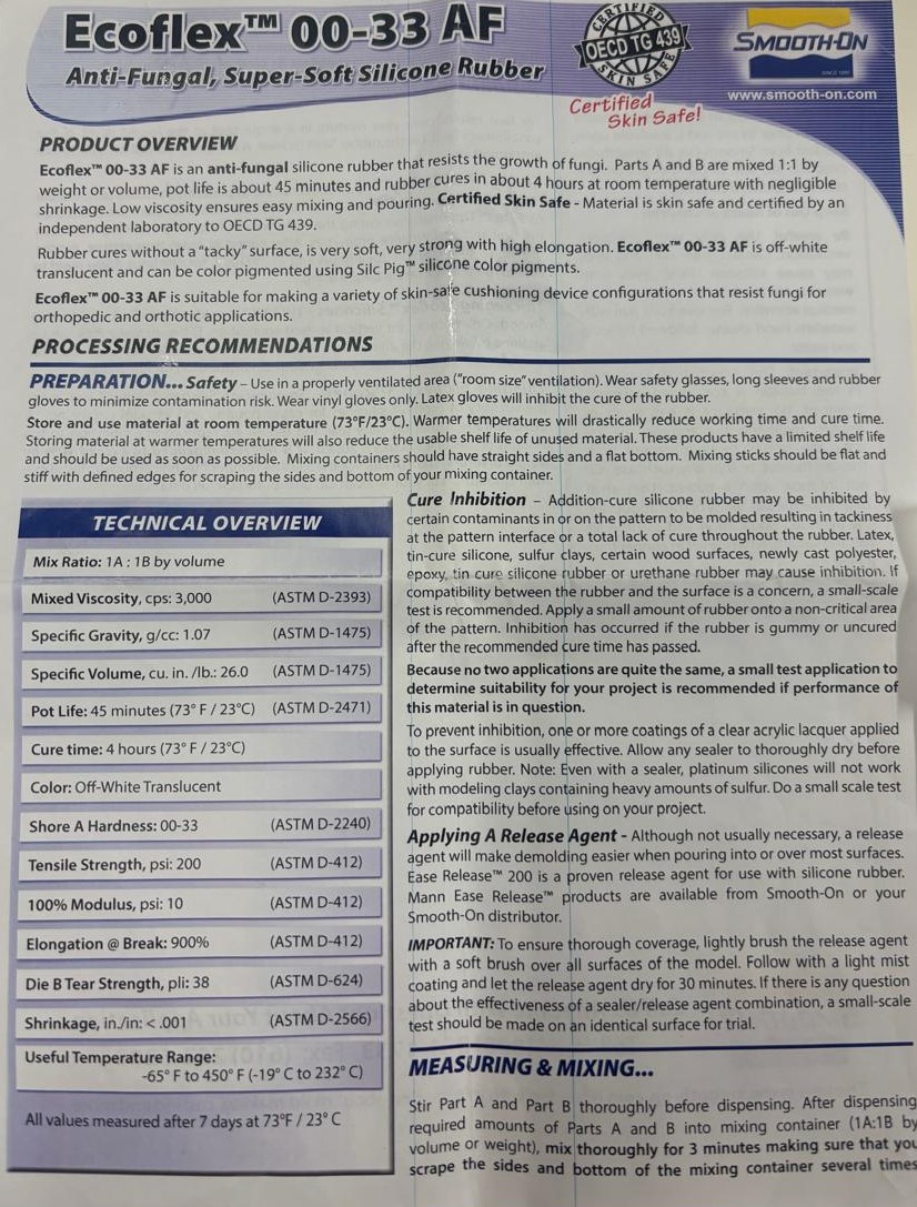
Ecoflex 00-33 AF, SAFETY DATA SHEETS


| Technical Overview | |
|---|---|
| Mix Ratio | 1A : 1B by volume |
| Mixed Viscosity, cps | 3,000 (ASTM D-2393) |
| Specific Gravity, g/cc | 1.07 (ASTM D-1475) |
| Specific Volume, cu. in./lb. | 26.0 (ASTM D-1475) |
| Pot Life | 45 minutes (73°F / 23°C) (ASTM D-2471) |
| Cure Time | 4 hours (73°F / 23°C) |
| Color | Off-White Translucent |
| Shore A Hardness | 00-33 (ASTM D-2240) |
| Tensile Strength, psi | 200 (ASTM D-412) |
| 100% Modulus, psi | 10 (ASTM D-412) |
| Elongation @ Break | 900% (ASTM D-412) |
| Die B Tear Strength, pli | 38 (ASTM D-624) |
| Shrinkage, in./in. | < 0.001 (ASTM D-2566) |
| Useful Temperature Range | -65°F to 450°F (-19°C to 232°C) |
| All values measured after 7 days at 73°F / 23°C | |
What i understood:
- 1. Mix Ratio: 1A:1B by volume.
- 2. Mixing: Combine equal parts of Part A and Part B. Mix thoroughly for 3 minutes, scraping the sides and bottom of the container.
- 3. Pot Life: 45 minutes at 23°C (73°F).
- 4. Cure Time: 4 hours at 23°C (73°F).
- 5. Optional: Use a release agent for easier demolding.
Note: Full properties develop after 7 days at room temperature.
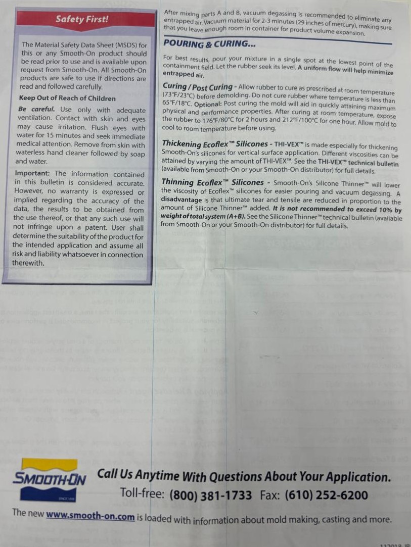
Mixing the Silicone


Curing
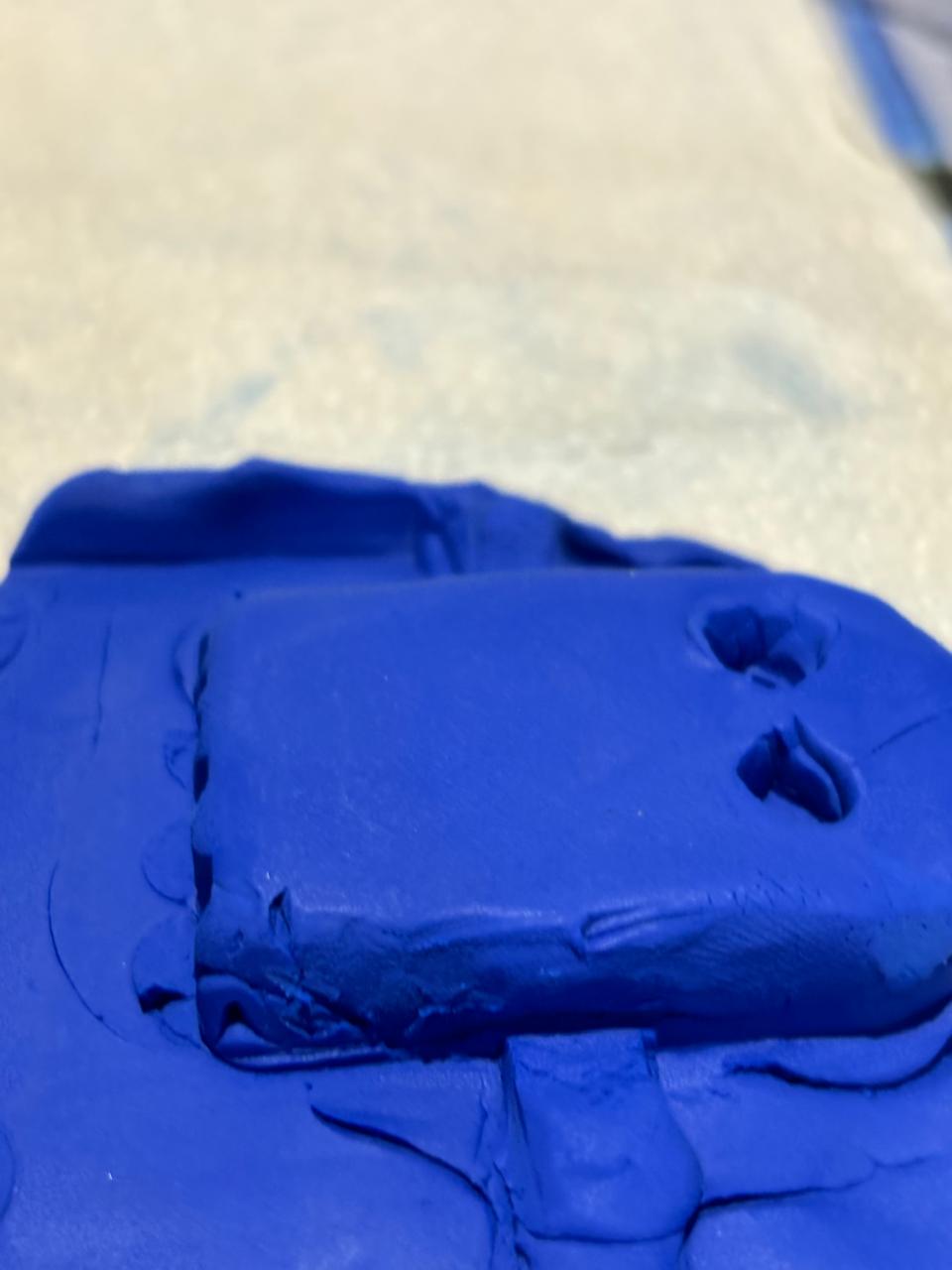
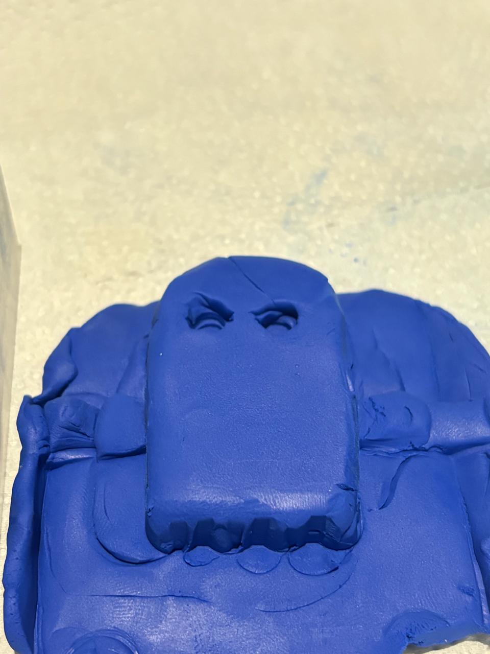
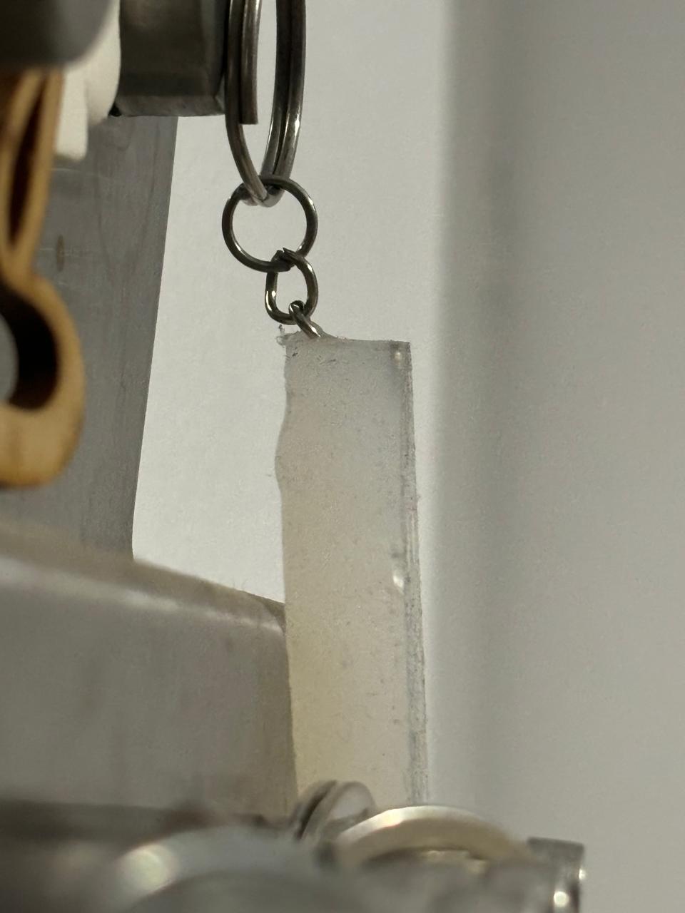
In my case i waited for almost 12 hrs until i took the keychain out of the mold.


Final results
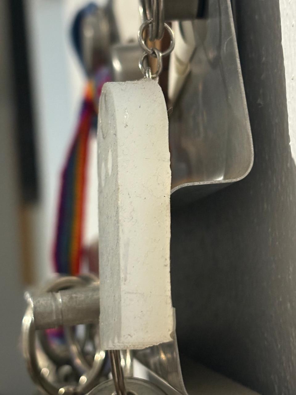
My new Keychain!!!!!
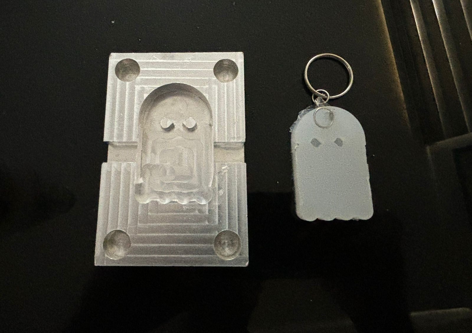
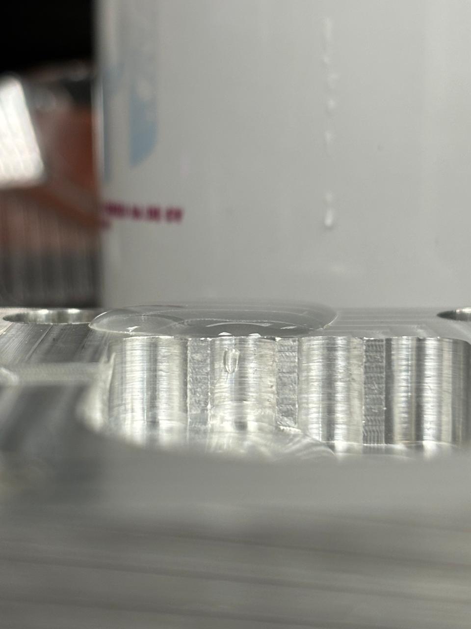
Smoothness ? YEAAH, take a look!
this is a good website where you can understand how it look like this and how you can improve in CNC milling 3erp
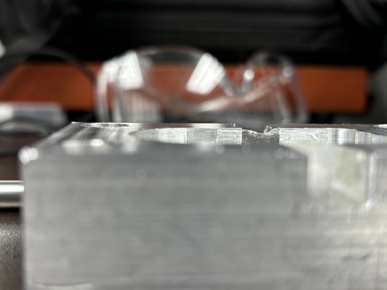
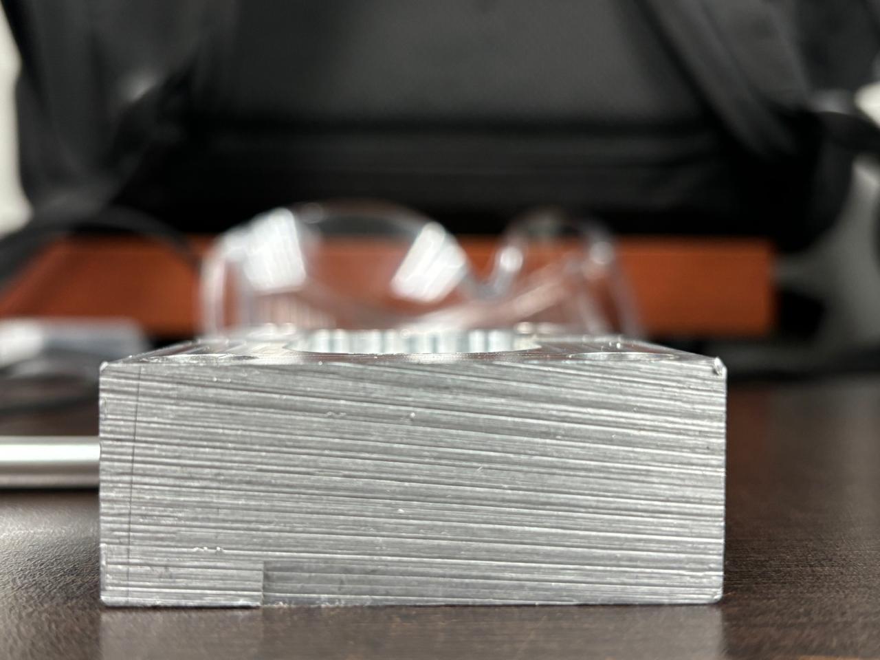
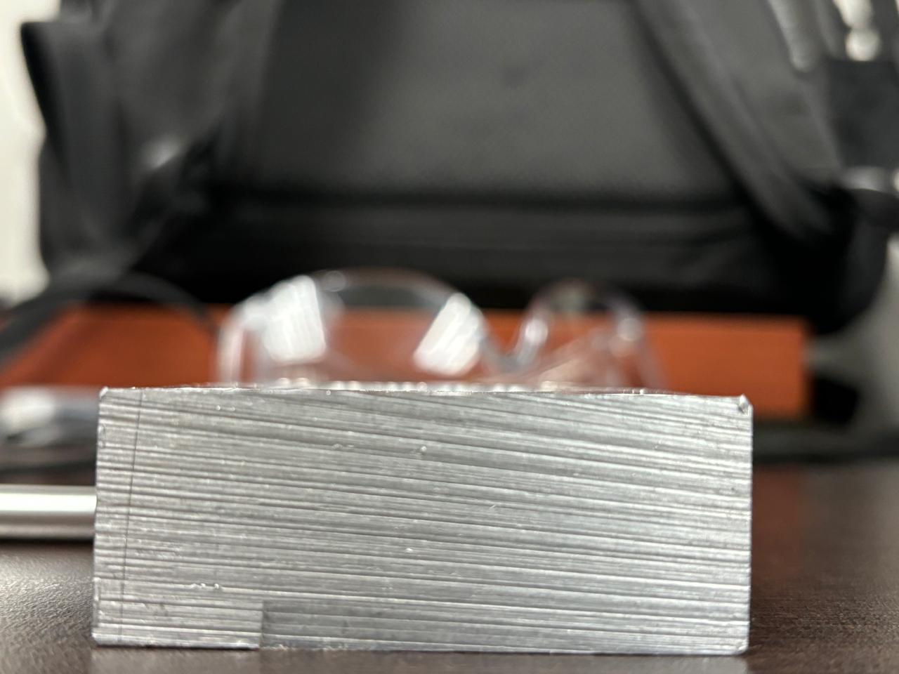
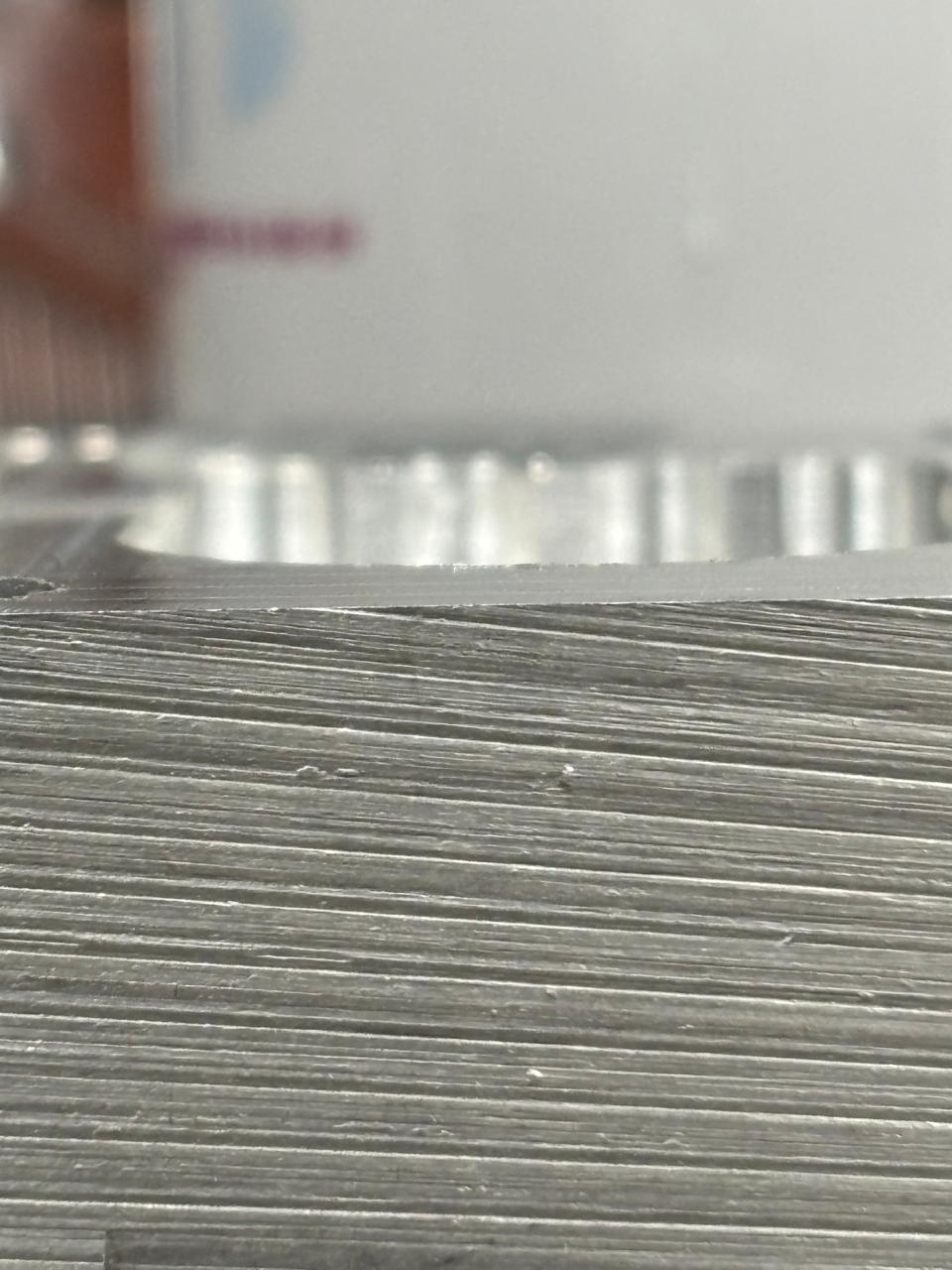
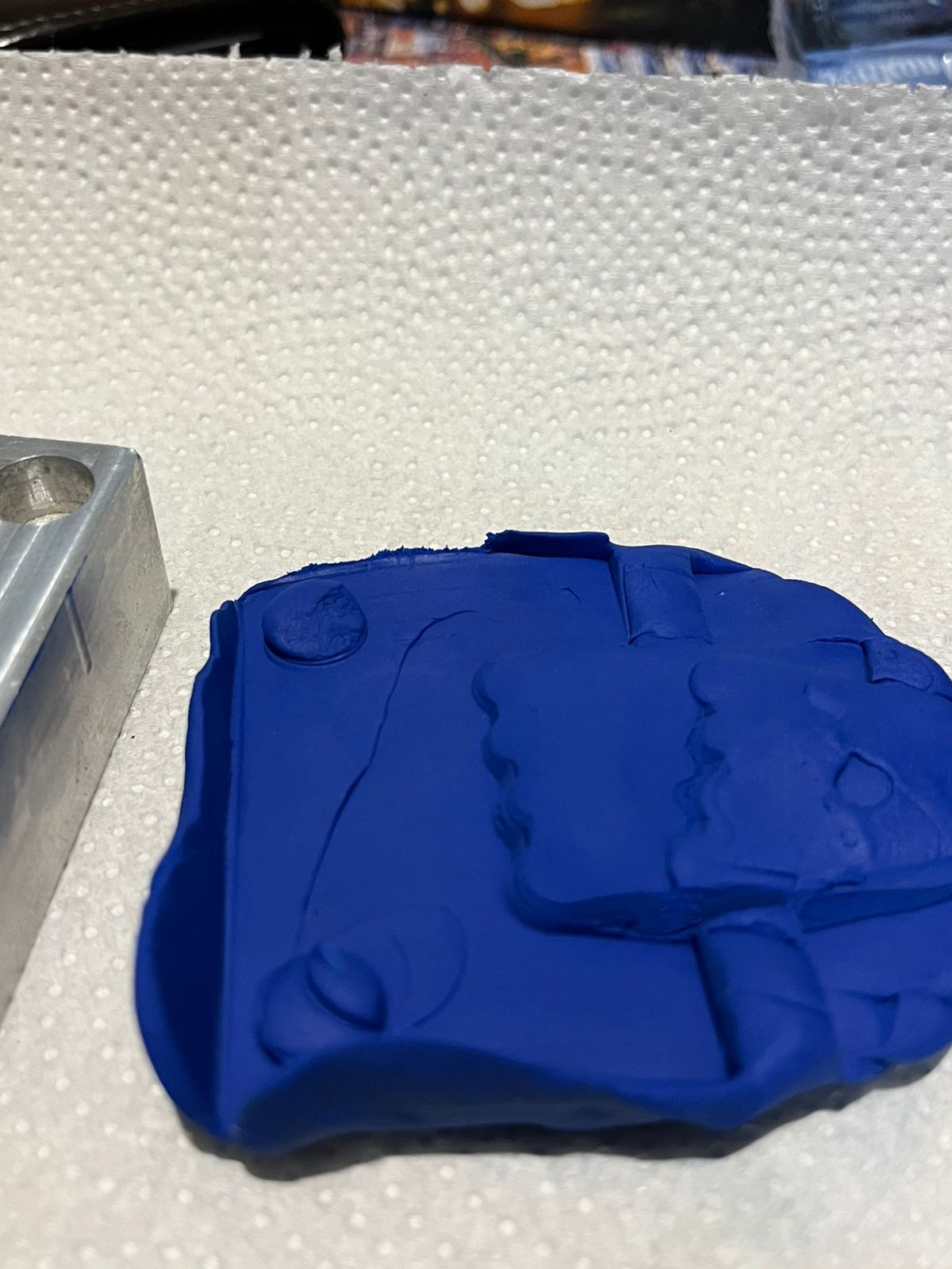
in the photos i uploaded before my mold looks like has a lines on the surface that doesn't show a smoothness surface, but this lines are for the following reasons. It just perspective of the photos, but when you touched it you can feel the smoothness surface.
G - code paramets
Spindle Speed: 3600 RPM
Feed Rates:
- Rapid movements: 2000 mm/min
- Cutting: 130 mm/min
- Contouring/Finishing: 1200 mm/min
CNC Machining Key Points
1. Toolpath Strategy
- Visible lines result from toolpath patterns (e.g., contour, spiral, zig-zag).
- Overlapping passes leave marks that appear as lines, even if the surface is smooth.
2. Spindle Speed and Feed Rate
- Imbalanced spindle speed (too low) or feed rate (too high) can cause:
- Tool deflection.
- Surface inconsistencies or chatter.
3. Tool Type and Geometry
- Flat end mills leave more noticeable lines compared to ball nose end mills.
- Large stepovers during finishing passes amplify visible marks.
4. Finishing Pass and Stepover
- An insufficient finishing pass or large stepover leaves traces.
- Reduce stepover to 10-20% of the tool diameter for better results.
Carrusel of photos, evidence #1
Videoproof #1
Carrusel of photos, evidence #2

