Week 3 Computer-controlled cutting
Computer-controlled cutting represents a transformative approach in manufacturing, design, and prototyping, leveraging computerized systems to precisely cut materials into specific shapes and designs. This technology encompasses various cutting methods, including laser cutting, waterjet cutting, and CNC (Computer Numerical Control) milling, each suitable for different materials and applications.

For this week we had to complete a vinyl and laser cut, including a parametric construction kit, i interprate this as a game like legos, where i can build what ever i want with i had. This assigment represented a lot of difficulties for me, at the beginning i wanted to built something interasting like this, but it was asking too much creative mind haha, i wanted to built also something with elements that aren´t flat, flexible, i did experiments trying to achieve a piece with 90 degrees to fold, i acquire the following thing, Considering the following image, I envisioned the pieces I could create from them. At the time, it occurred to me to have a parametric kit to make a bag where these two folded to obtain a bag, and then if I disassembled it, it was a tablecloth and shin guards for playing soccer.
However, I felt it was not enough. I started looking for ideas on the internet for pieces that had already been made with MDF or wood, and I found chess sets. I was inspired to make a chess set, where all the pieces serve to assemble each of the pawns, rooks, bishops, knights, king, and queen, in addition to turning into English draughts.
Here is the Group assigment of our Fab Lab Puebla. : link
AssigmentGroup assignment:
Files
- Laser cut
- Vinil cut
Step 1: Chess table
In the image below, draw a board of 220x220 mm with 10 mm rounded corners. Draw it using 'Center Rectangle' to ensure that when assigning the desired measurement variable, it adjusts automatically.

Afterwards, draw the inner square with dimensions of 200x200, and also draw two lines, one horizontal and one vertical, with the following measurements:

To subsequently use the linear pattern function and draw the other vertical and horizontal lines that complete the chessboard pattern.

Here, I added the desired board measurement to the equation variables.

And I modified the previously assigned measurement with the equation.


Here's an image showing the final result of using the linear pattern function to fill the board, and to draw the diagonal lines and reference the black color when translating it to the MDF cut, I drew straight lines from side to side and erased them where I didn't want them to scratch (the white squares).

Step 2: Equations and global variables
To parameterize the parts and have them related to each other among the different pieces that I'm going to draw, I prepared these measurements in "Equations".

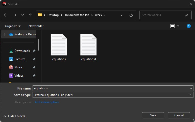
Afterward, to have these measurements as global variables, we will need to save all my documents that I will later assemble in the same folder, and I will import them and then export them.
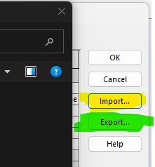
I saved this document in the same folder as all the other documents.
Step 3: Designing chess pieces
Base for all the chess pieces
This is the sketch for all the pieces; they have those four rectangles because that's where the bodies of the chess pieces will fit. And in the next ones i draw the silloutte of the chess body pieces, where i made the dimensions of the base where it will fit with the first image, parametric to the same dimensions.
Then i extruded wtih the mdf thin, to assembly at the end and verify it all fit together.

Tree pieces for usign your imagination
After that, I drew three sketches that in my imagination could be assembled in different positions to form the knight, the bishop, the pawn, the king, and the queen.
* I assembled the pieces in SolidWorks to verify that they would fit within the software and also to see if my configurations could work.
I transferred them to a drawing, to place all the pieces I needed to assemble the 32 chess pieces, and I exported them in .DXF format into my USB.

Step 4: Cutting on the lasercut
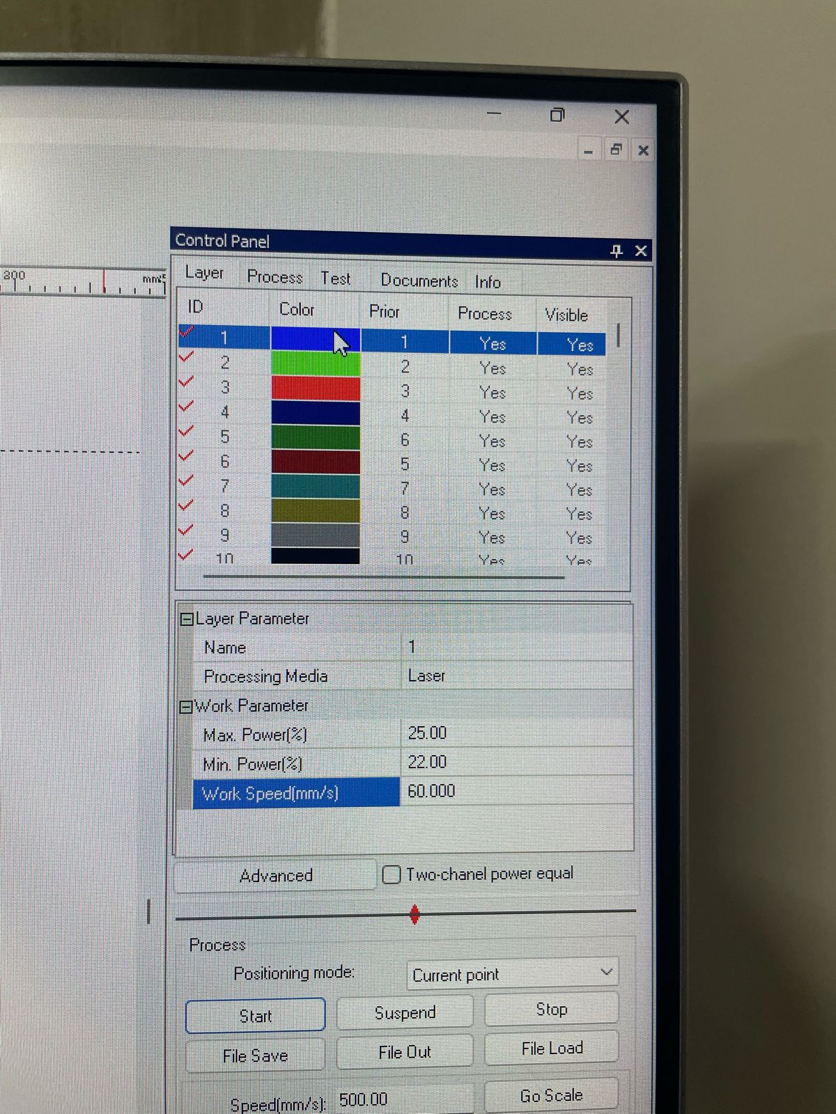
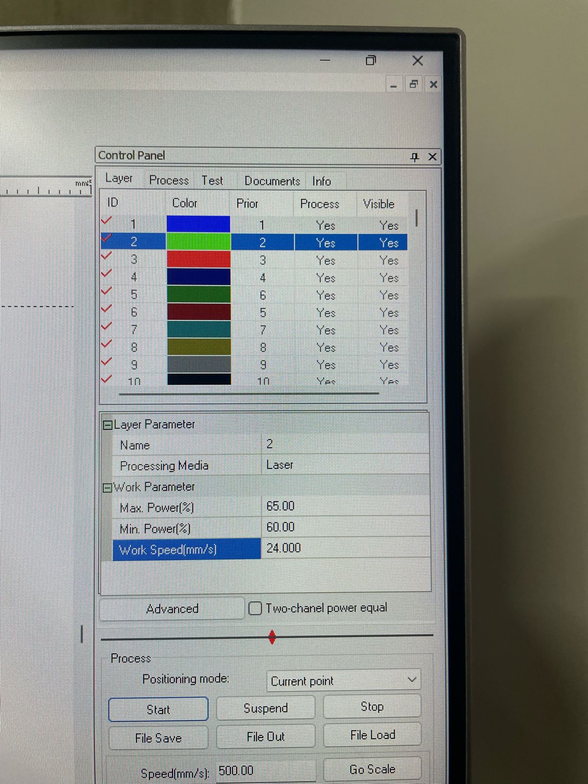
Parameters
1.The first image shows the settings for ENGRAVING, with 25 of MAX POWER and 20 of MIN POWER, and a speed of 60 mm/s.
2.The second image shows the settings for CUTTING, with 65 of MAX POWER and 60 of MIN POWER, and a speed of 60 mm/s.
* These settings depend on each machine; in our case, these were the settings we found to be suitable for engraving and cutting in our fab lab.
Practicing for choose the best dimensions to fit perfectly
I performed many practice cuts first to verify the correct kerf and laser height, so that I could make a final cut of everything without wasting too much material. The first thing I cut was the board, followed by some pieces for testing.
And here are my first pieces which i used to practiced
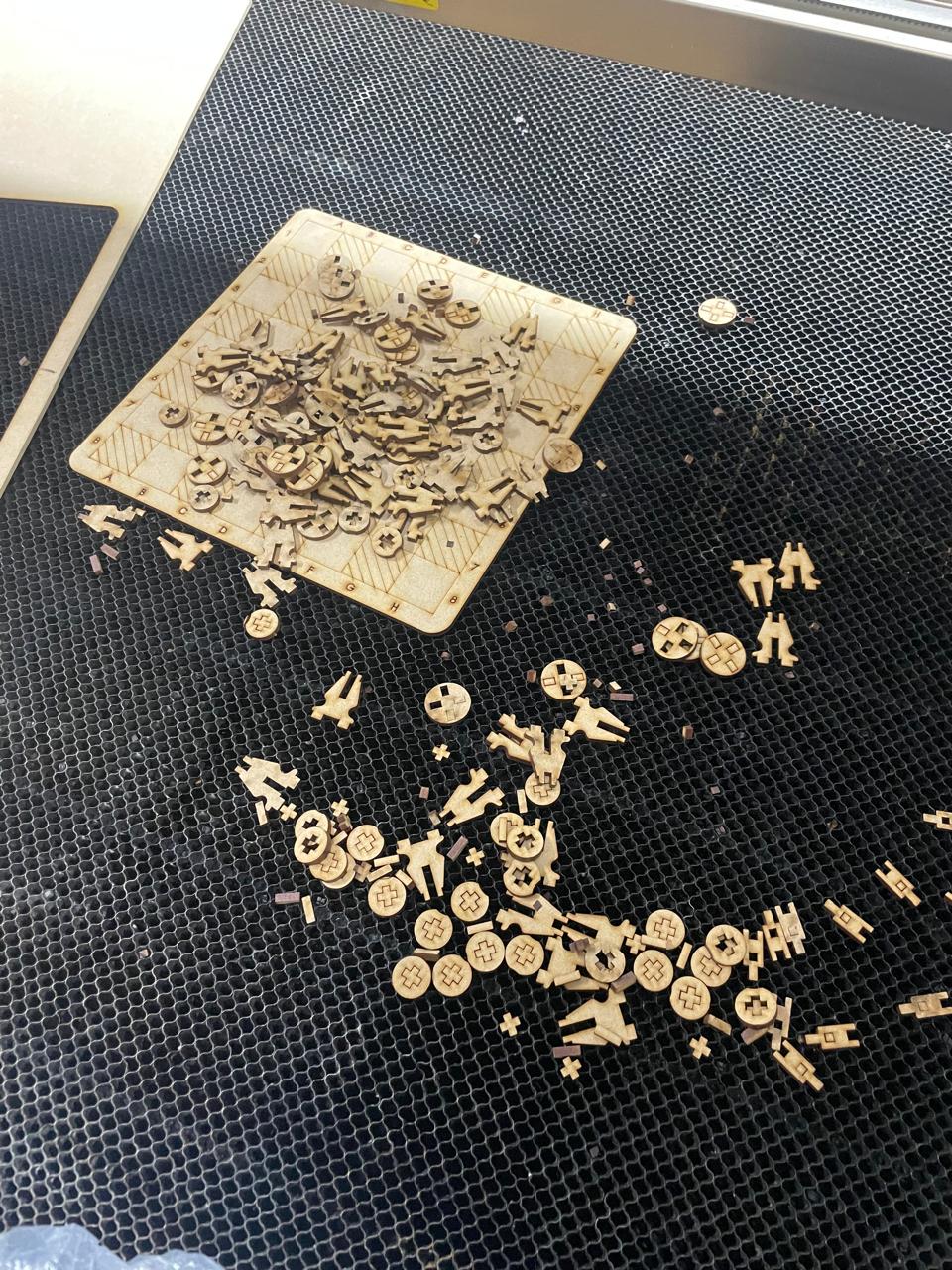
Here i cutted the main DXF file with all the pieces
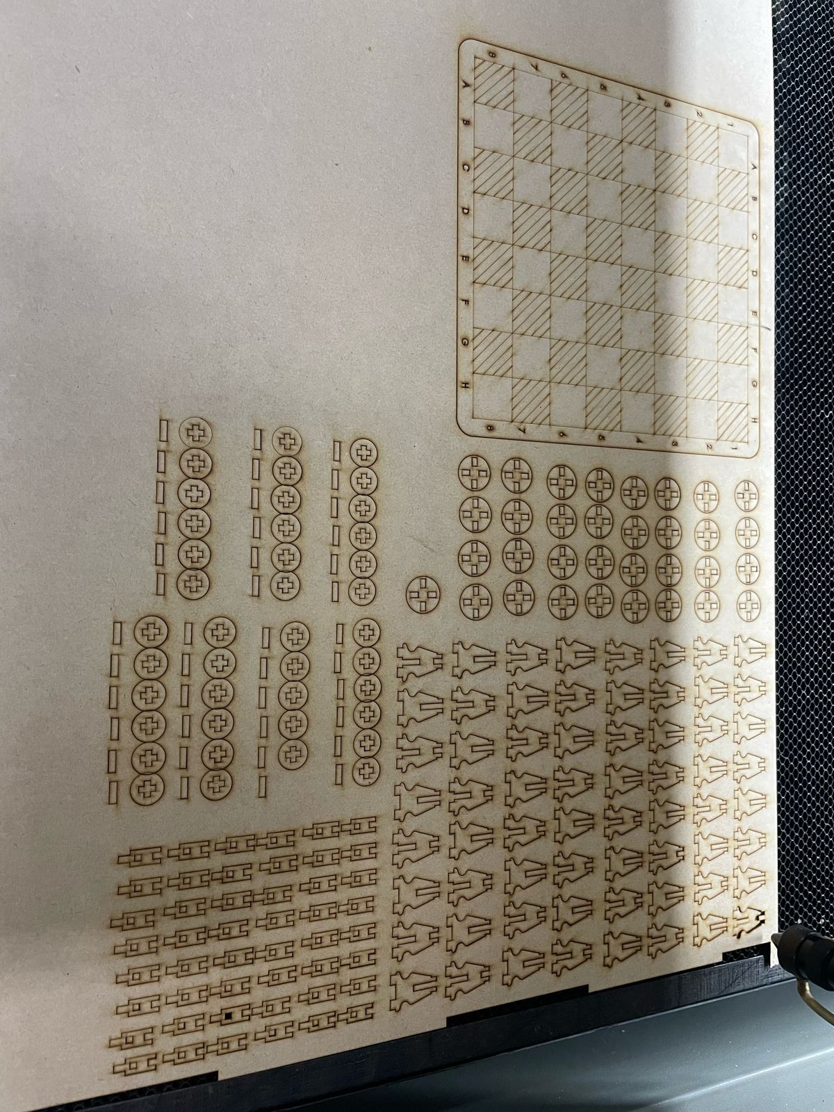
Step 5: Kerf parameterized (Added to fix an issue)
22 / Nov / 2024I miss add a parameter for the KERF, "Kerf is the width of material that is removed by a cutting process, such as CNC milling or hand-cutting with a saw. The term was originally used to describe how much wood was removed by a saw." hat i did was only add the 0,2mm (this number i got it meanwhile i was laser cutting my pieces, at the beginning i only wrote the exact numbers to grap in but i had to add 0.05 then 0.1 mm to ensure the engrave of the pieces between them ) on the MDF parameter, so now i add a new equation for KERF, which i will used in the others equations to move automatically when i or you get the KERF of your machine, remember that each machine has one and it changes for a differents reasons such as maintenence.
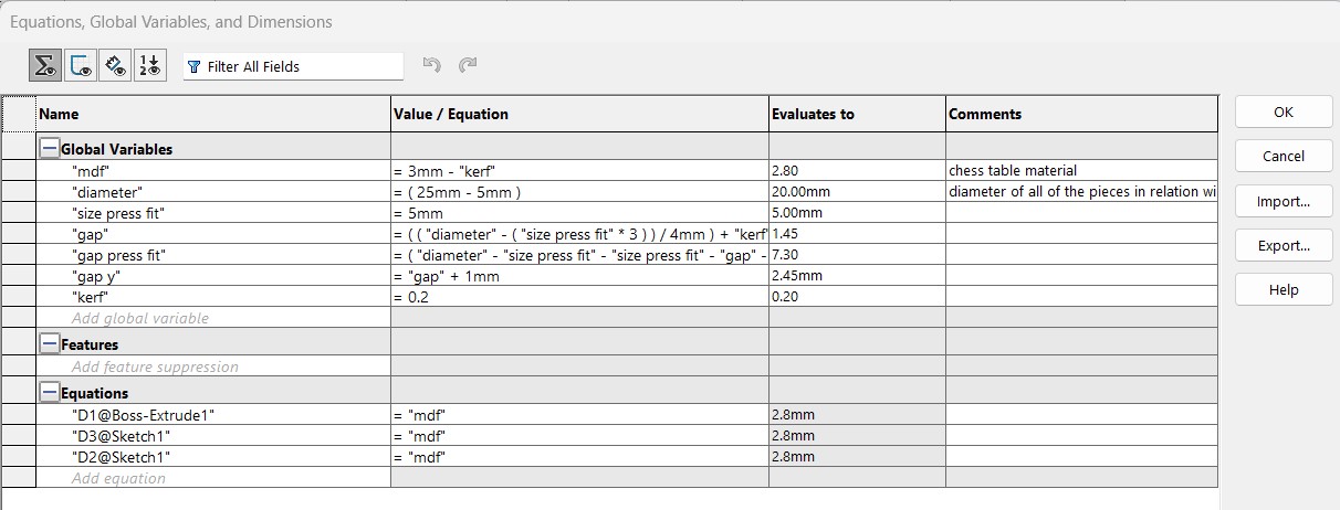
I exported in the my folder where i save all my files of the projcect, with the objective to import into the other SolidWorks Parts.
What i have here is a sample book of my Kerf trials, where I experimented with the entry and exit clearance of my chess pieces to make sure they didn't fall because they were too loose, but not too tight so that they could enter easily the first time.
From them, I decided to define the Kerf of 0.20mm marked as 3.20 in my image (from the sum of 3 of the MDF and 0.20 of the kerf)

Step 6: Assemblying the chess
Here are my pieces after i cutted on laser
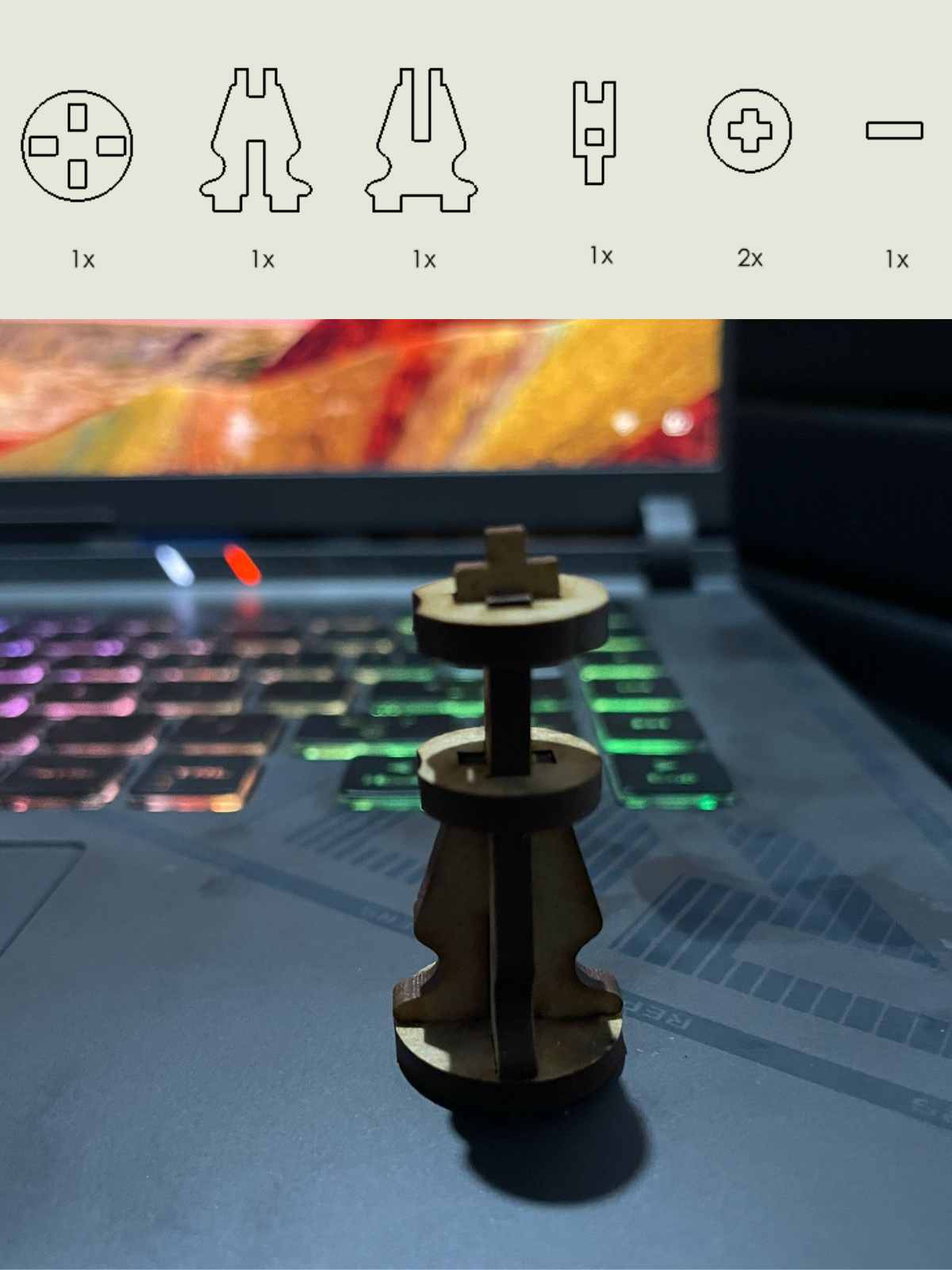
These are the amounts of materials needed to assemble each of the chess pieces.
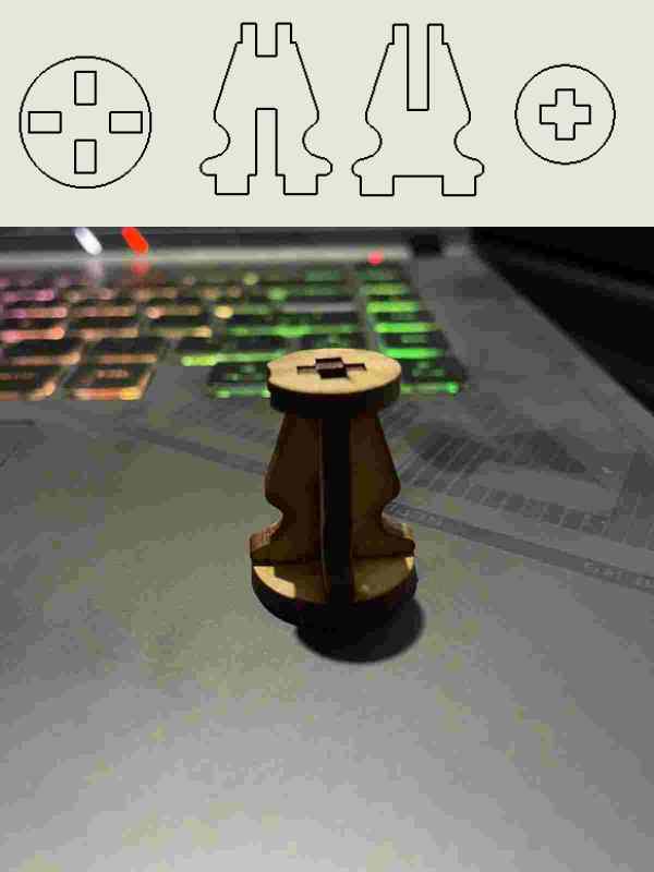
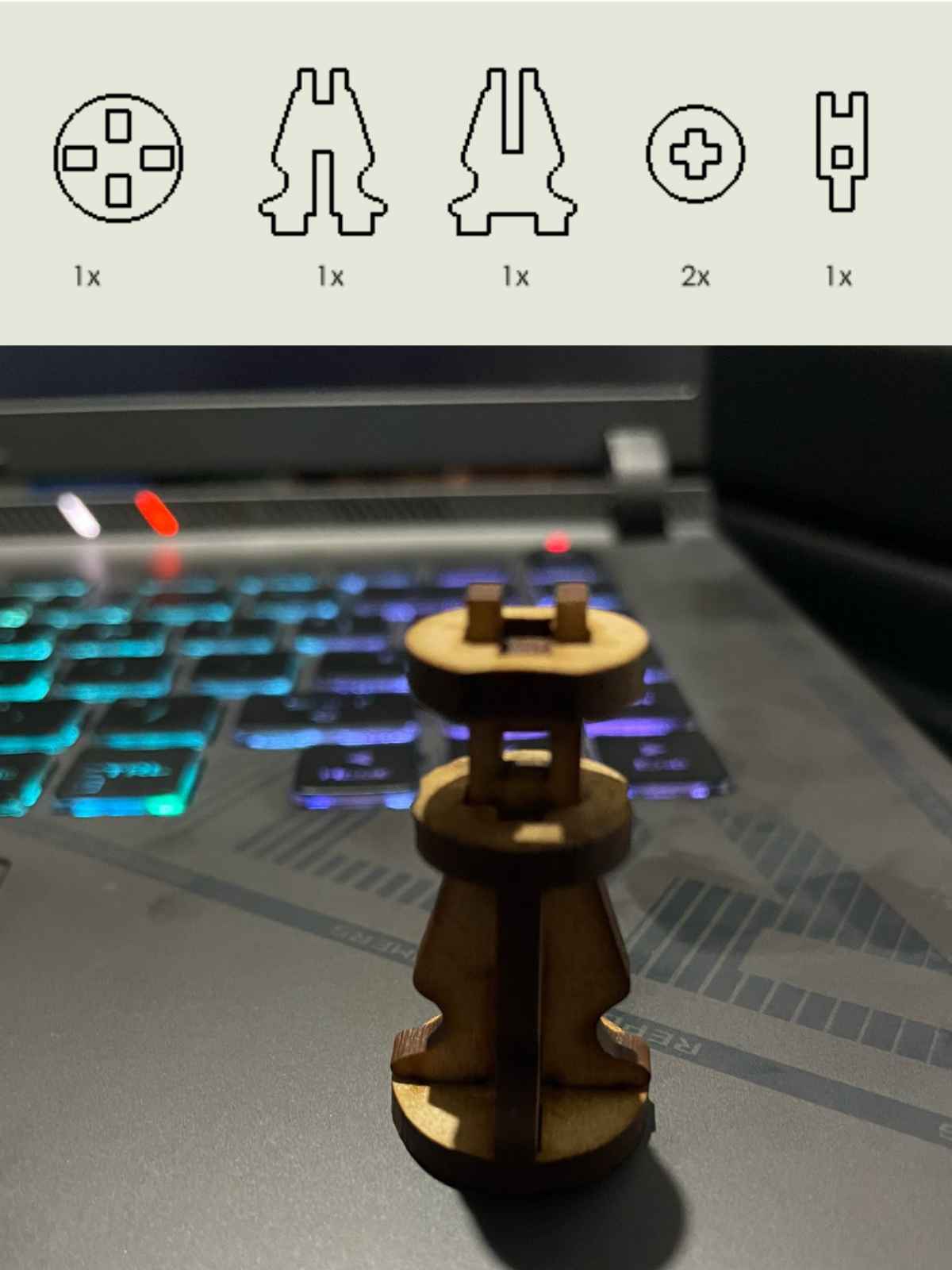
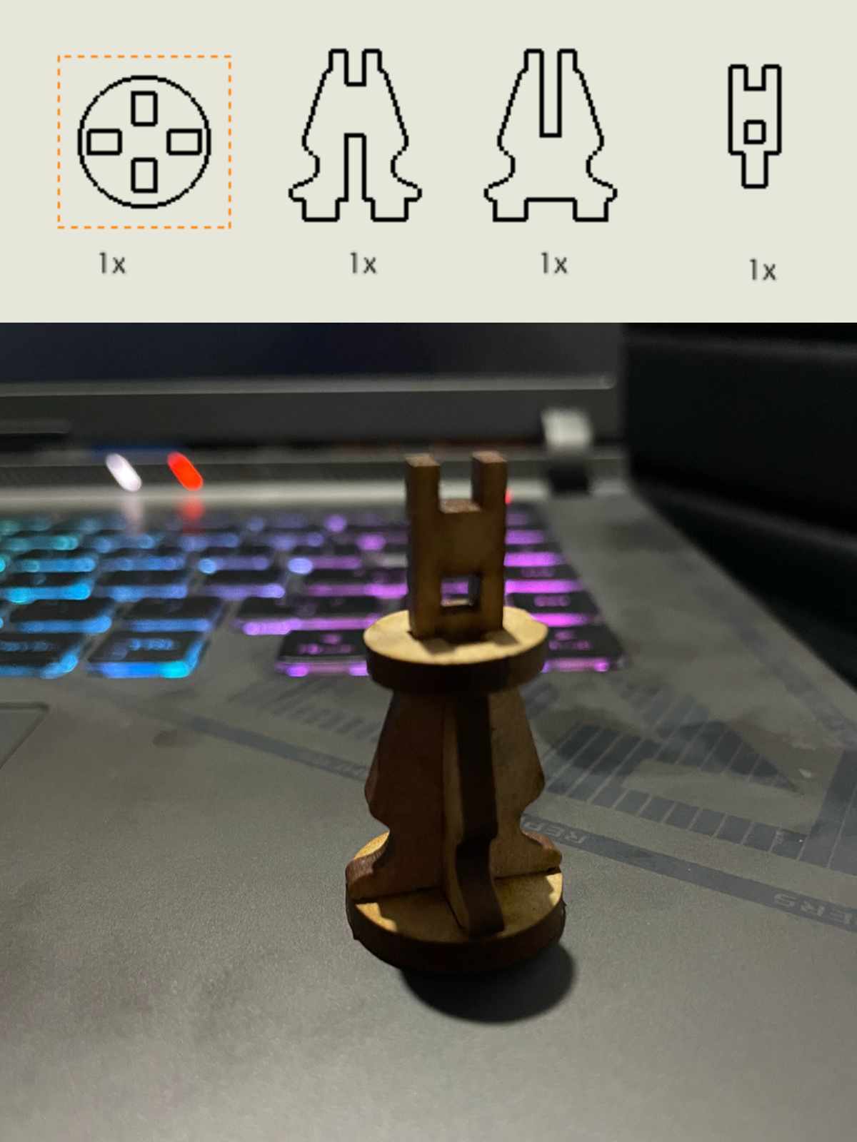
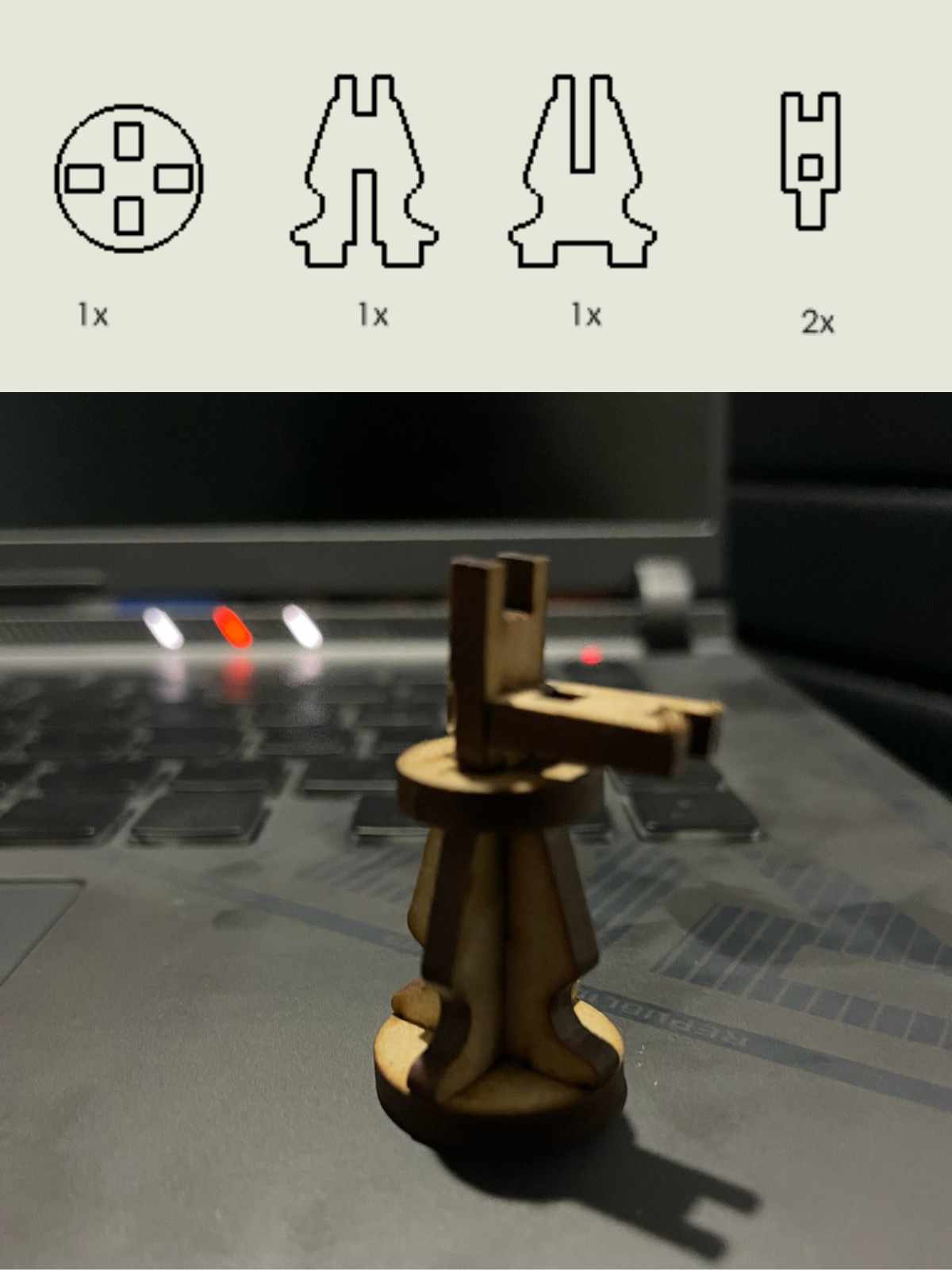
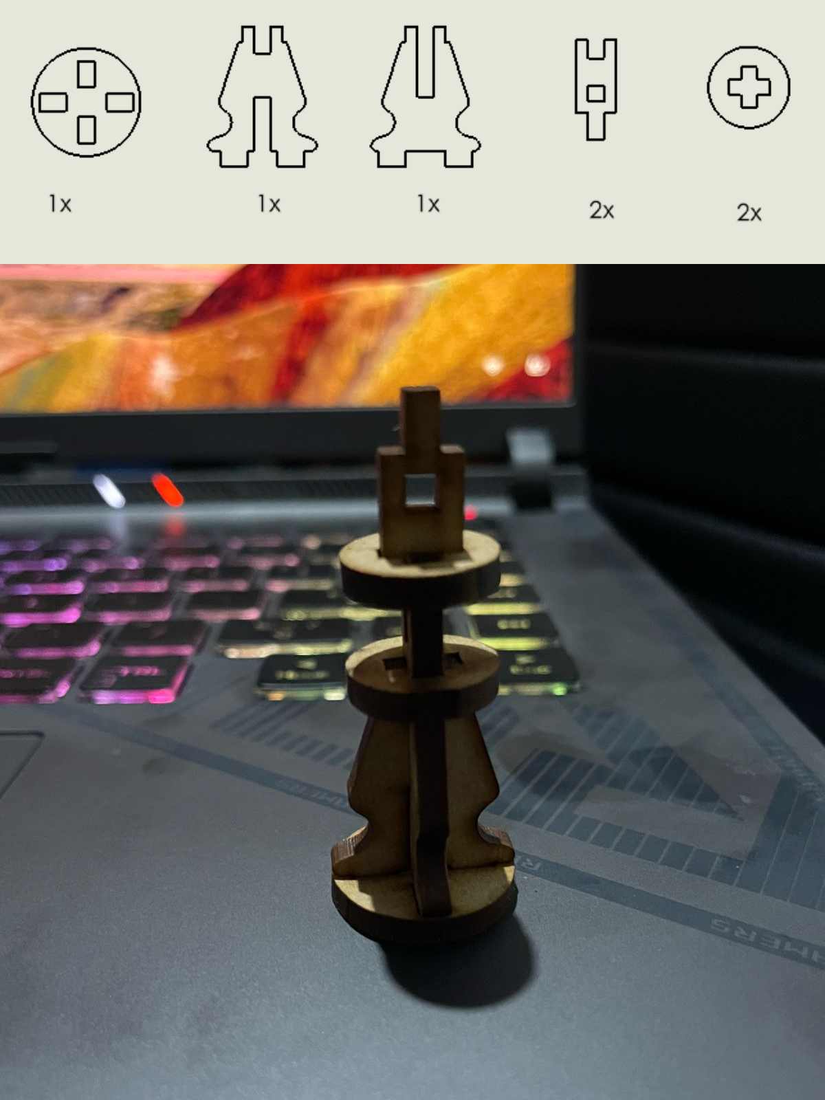
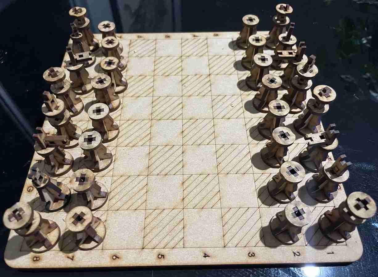
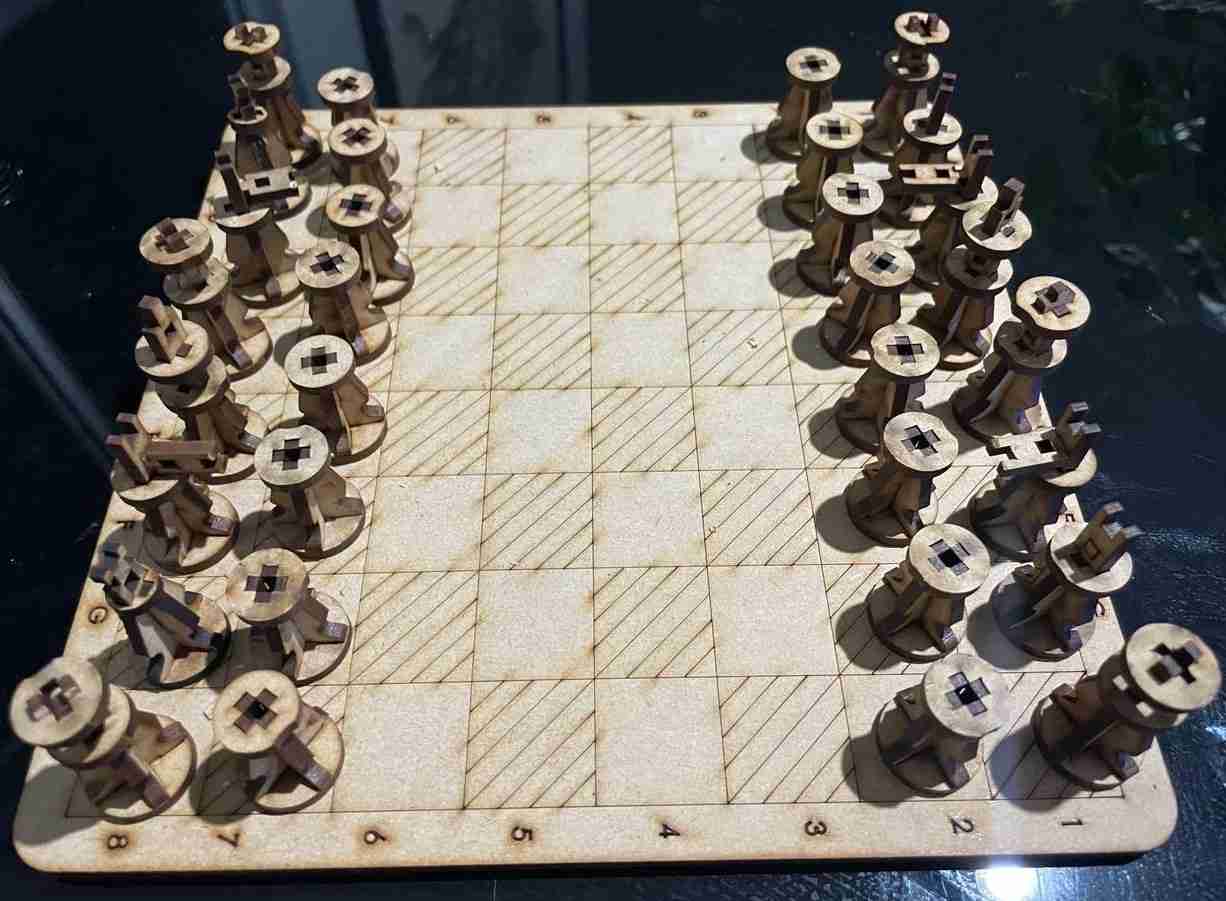
The final product, the chess with mdf
Vinil cut
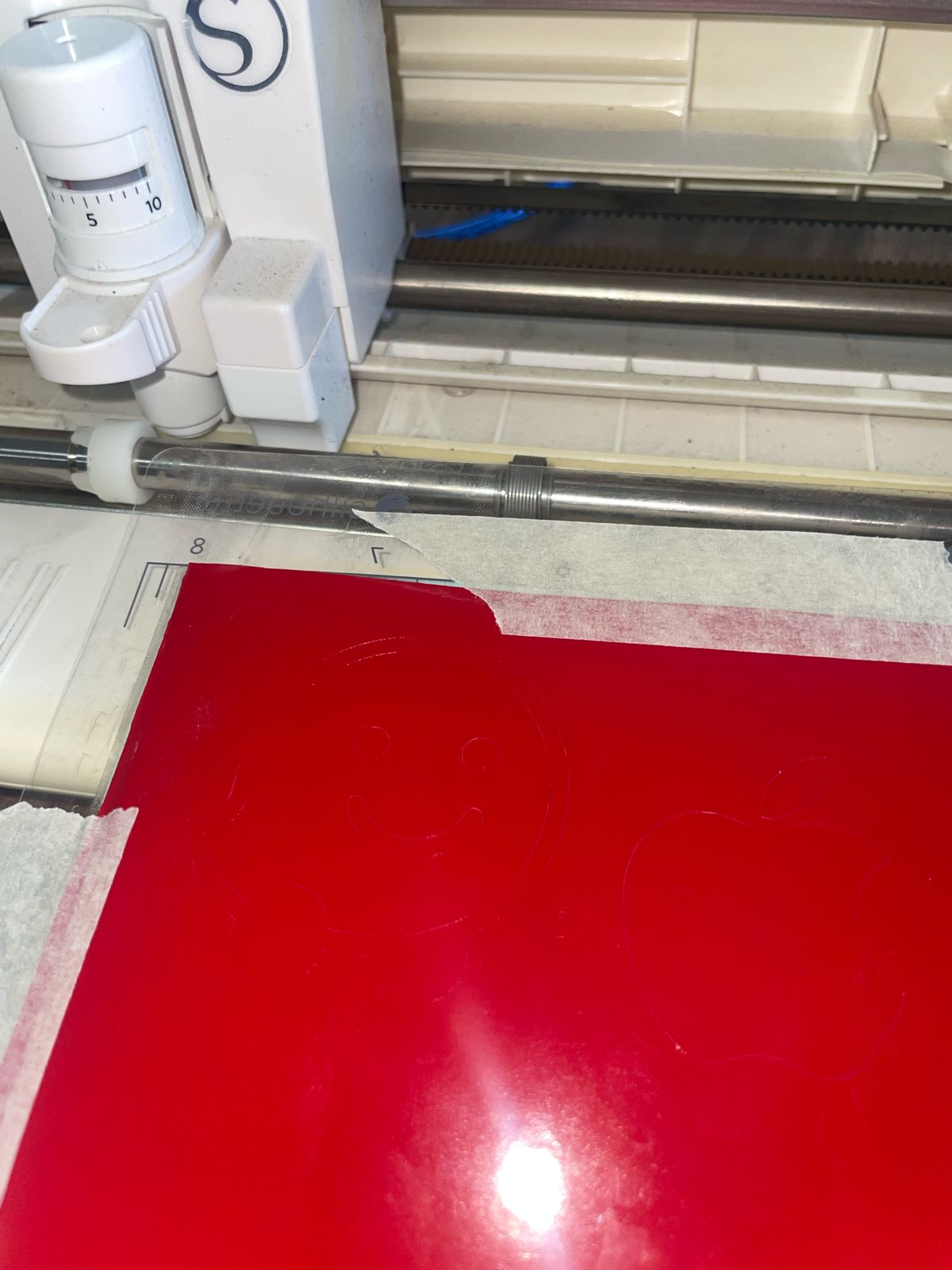
To cut vinyl, I used the Silhouette software, which you can download here . This software was very easy to understand because you just dragged the PNG image into it and it automatically vectorized.
Step 1
Create a new file > import your imagen on PNG format > visualize the size on the blank page where you could change the dimensions > Send to the vinil cut


These are the configurations i used to cut on vinil

Step 2
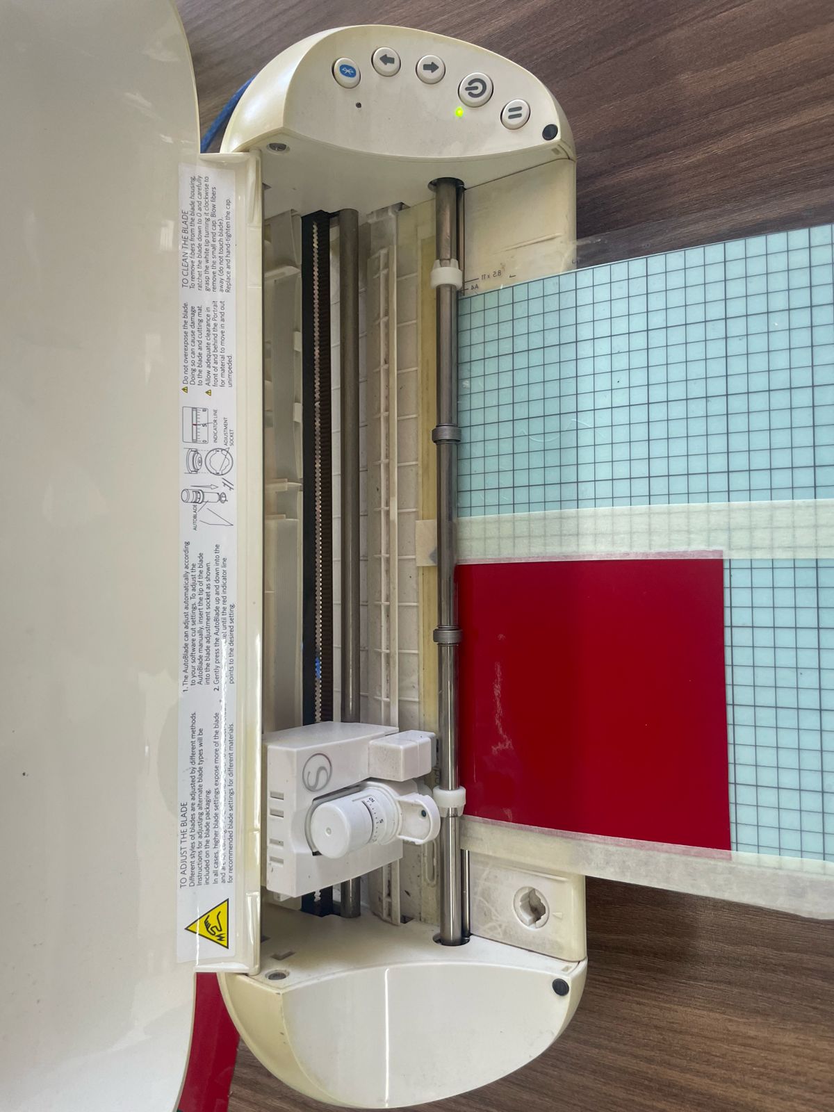
Power on the Silhouette device > colocate on the origin and allign it with the arrows > Cut it


