Week 2 Computer Aided Design
CAD, or Computer-Aided Design, revolutionizes design processes across industries with precision and efficiency. From architects to engineers, CAD software empowers professionals to conceptualize and refine designs with unparalleled accuracy.
In this week i will experience with different designing softwares, first i need to remark in my entire life i had been only interactive with Solidworks, Catia, Ansys and a bit of photoshop.
Which softwares could you use for 2D and 3D design?
DXF : to cut in laser
STL, STEP : for open any file in any program
- 3D design
- 2D design
- Possible final project
I will use solidworks and catia to compare interface and how it works each. I took one of my other class activities.
The plane is the next one :
solidworks
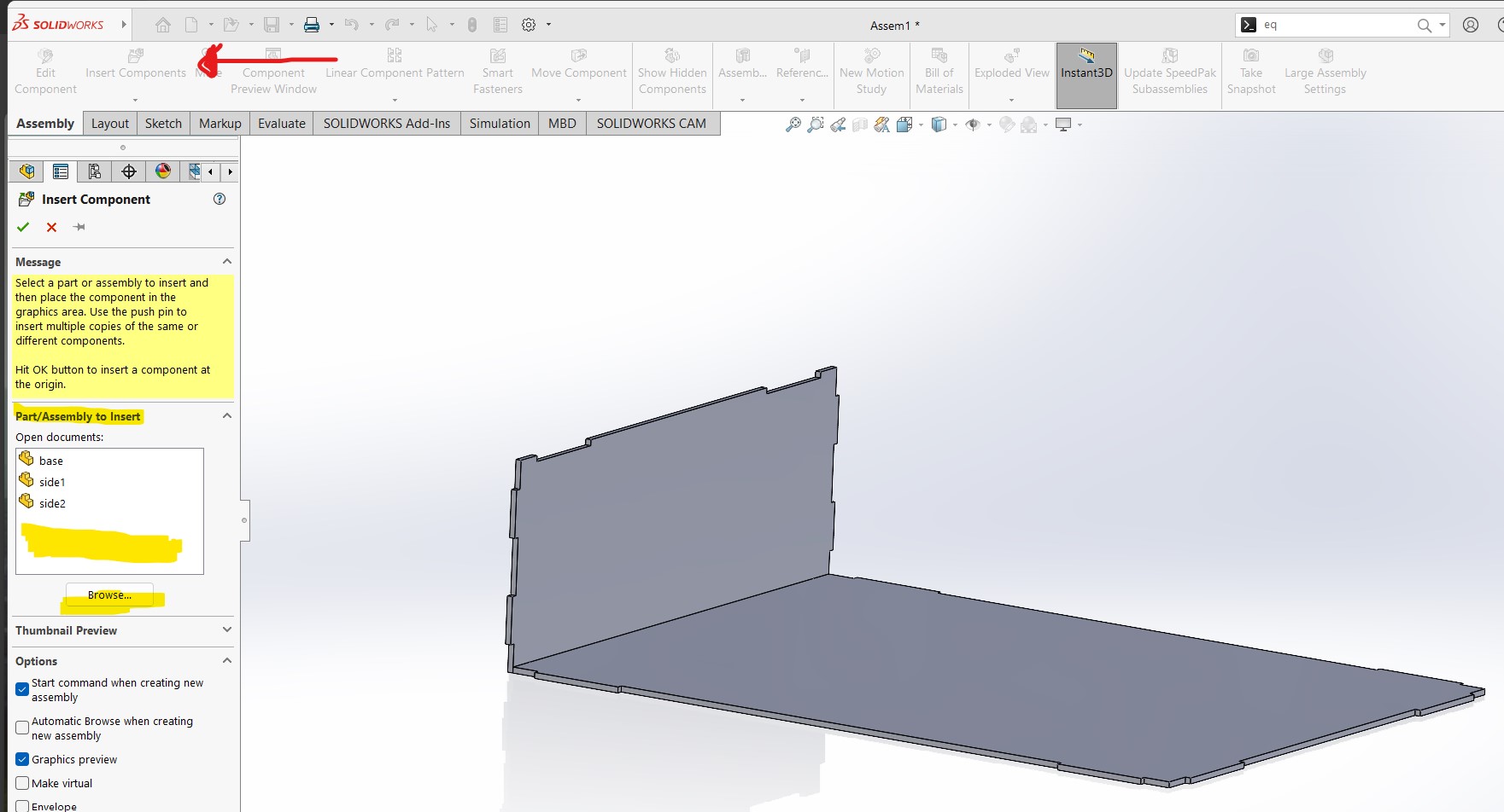
Here you are going to select Part
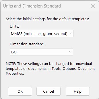
this window its very import to remark you already had to know in which units are you going to work, mm, m or cm. Usually you will work on mm.
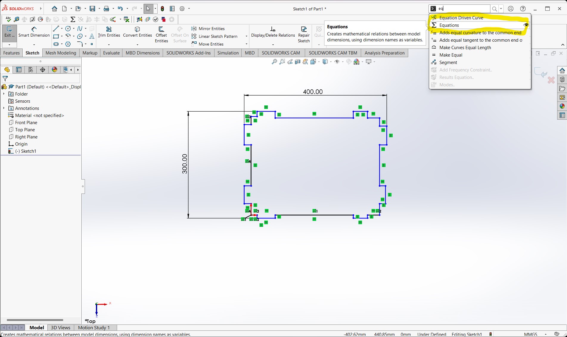
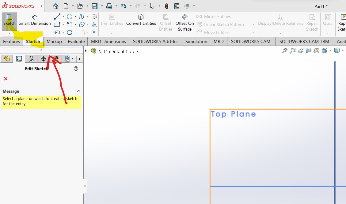
Now you'll see in the left top the follow tab named "sketch", click on to select one of the planes (XY, YZ, XZ)
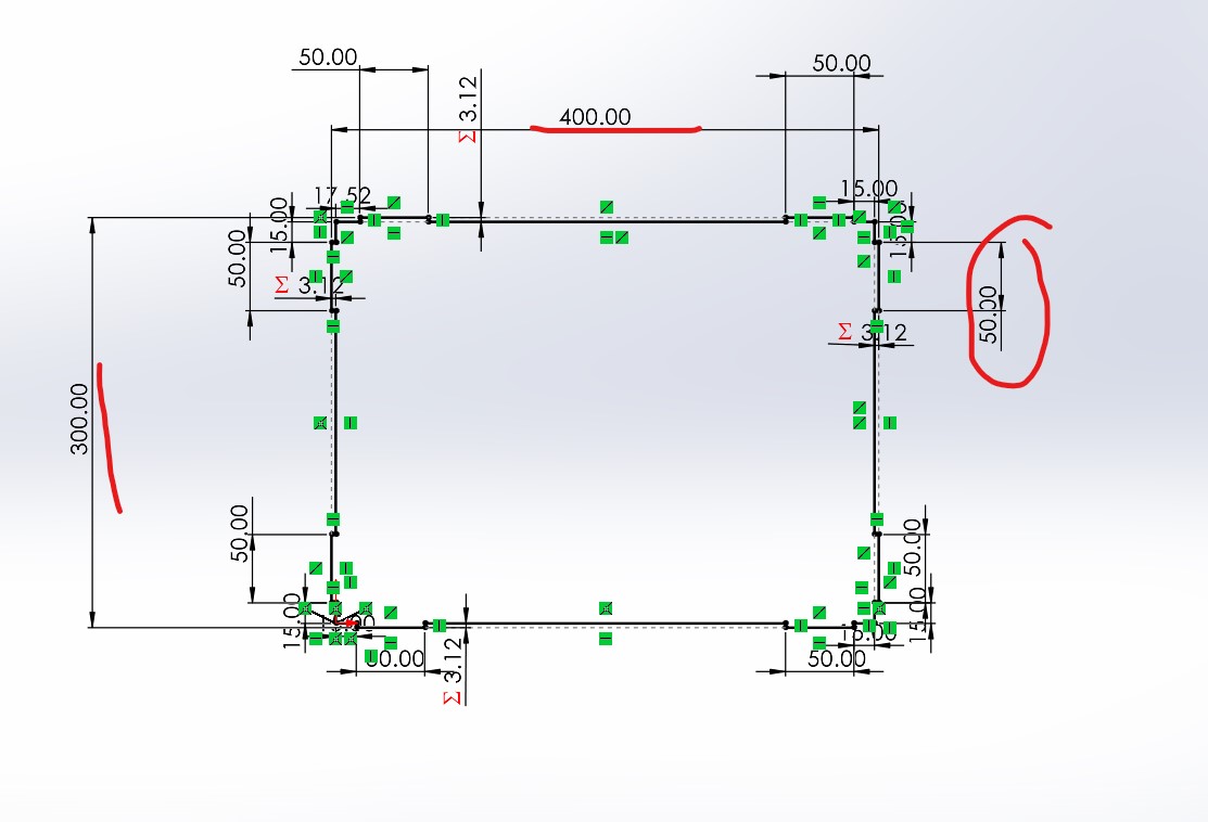
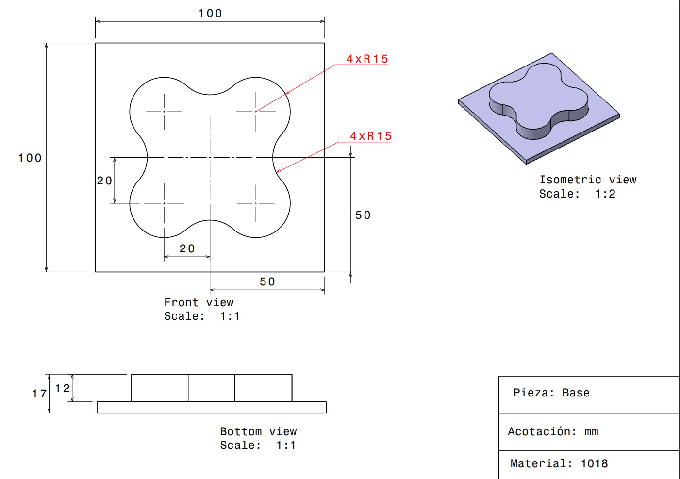
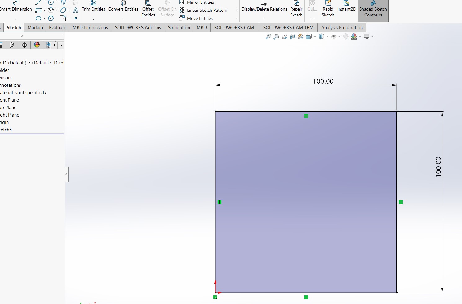
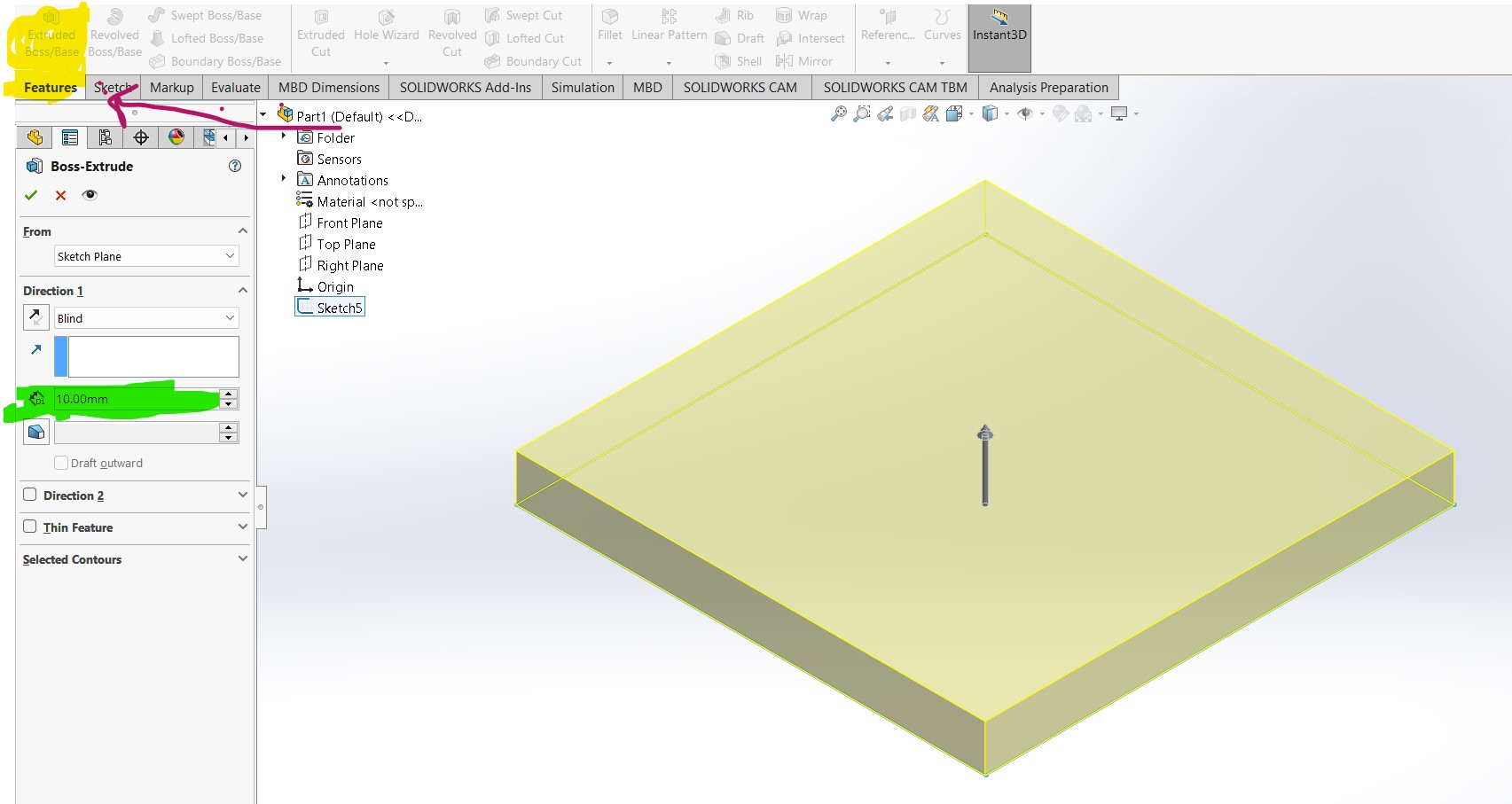
I draw a 100 mm square, using the Corner Rectangle feature, and for showing the measures the Smart Dimension option. Remember where is the Sketp option? In the same place now is "Exit" you have to click it to extrude the sketch.
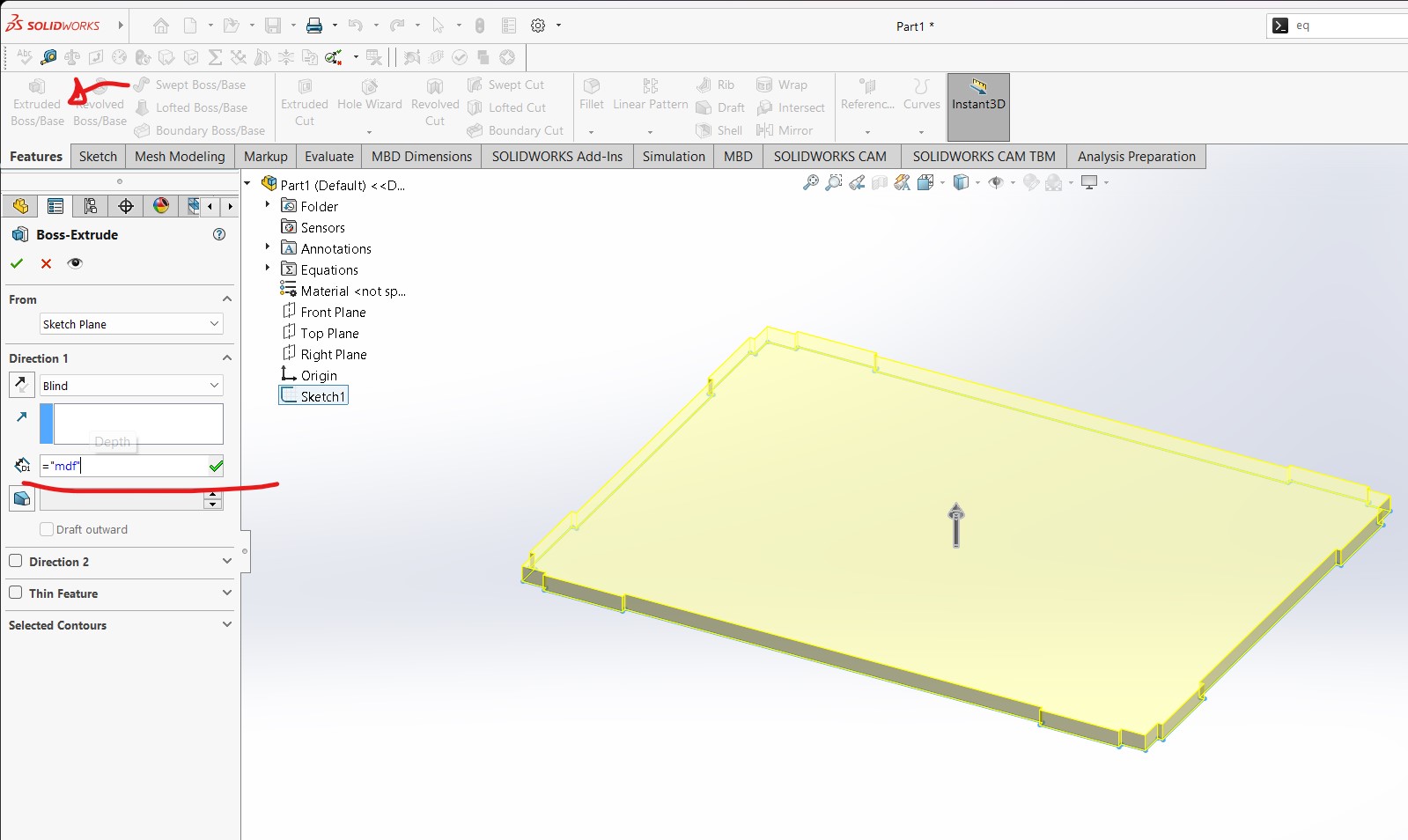
To extrude click in the first tab "Features" point it with the red arrow, and you will be able to change how much you will make the pad
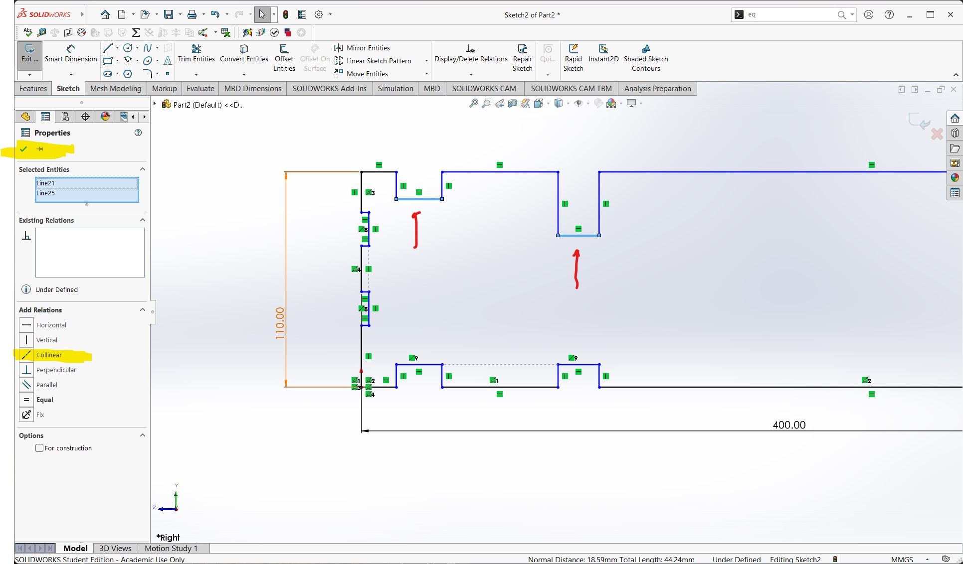
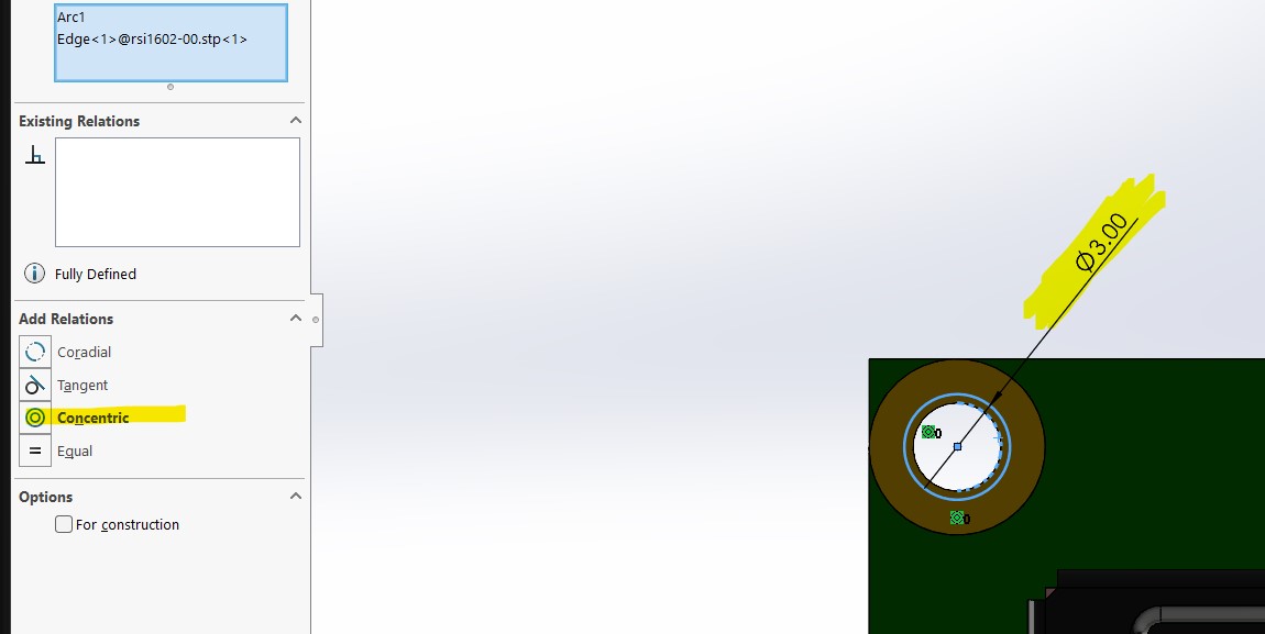
To sketch click to place the center of the circle where you want it, then drag and release to define its radius i did it in each circle you saw. One thing i love of solidworks is the constraints options appears in side bar, so you dont have to click it and move into another window also if you select an object in the same bar will show if already had any existing realtions, it helps when you clicked before and you dont remember.
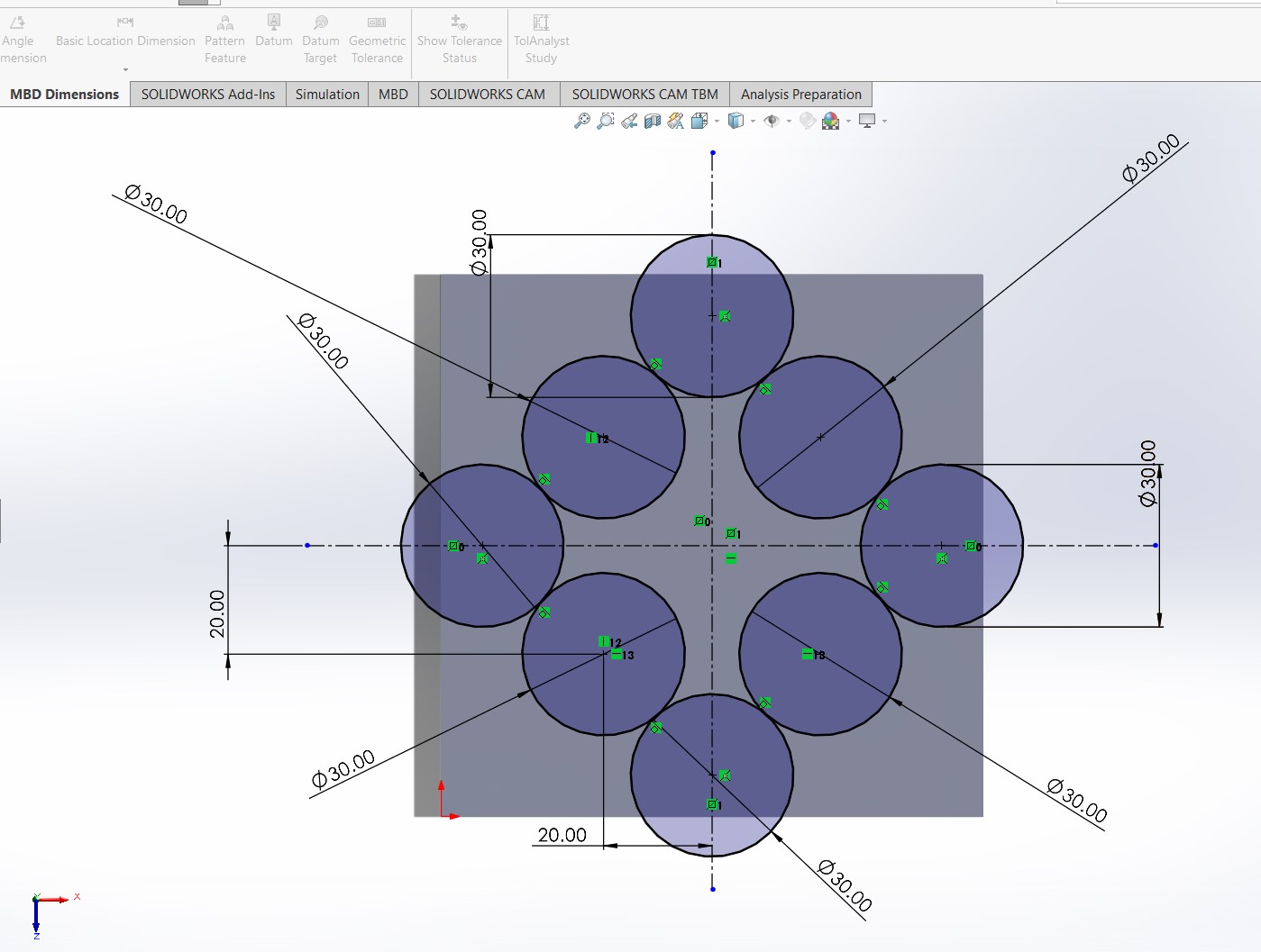
We notice that the image we see drawn with the circles in the sketch is somewhat different from how it should look? Well, in order to ensure that the sketch is closed and we can extrude it, we need to erase some of the intersections between the circles using the 'trim' operation selecting and experimenting which lines would not want to have.
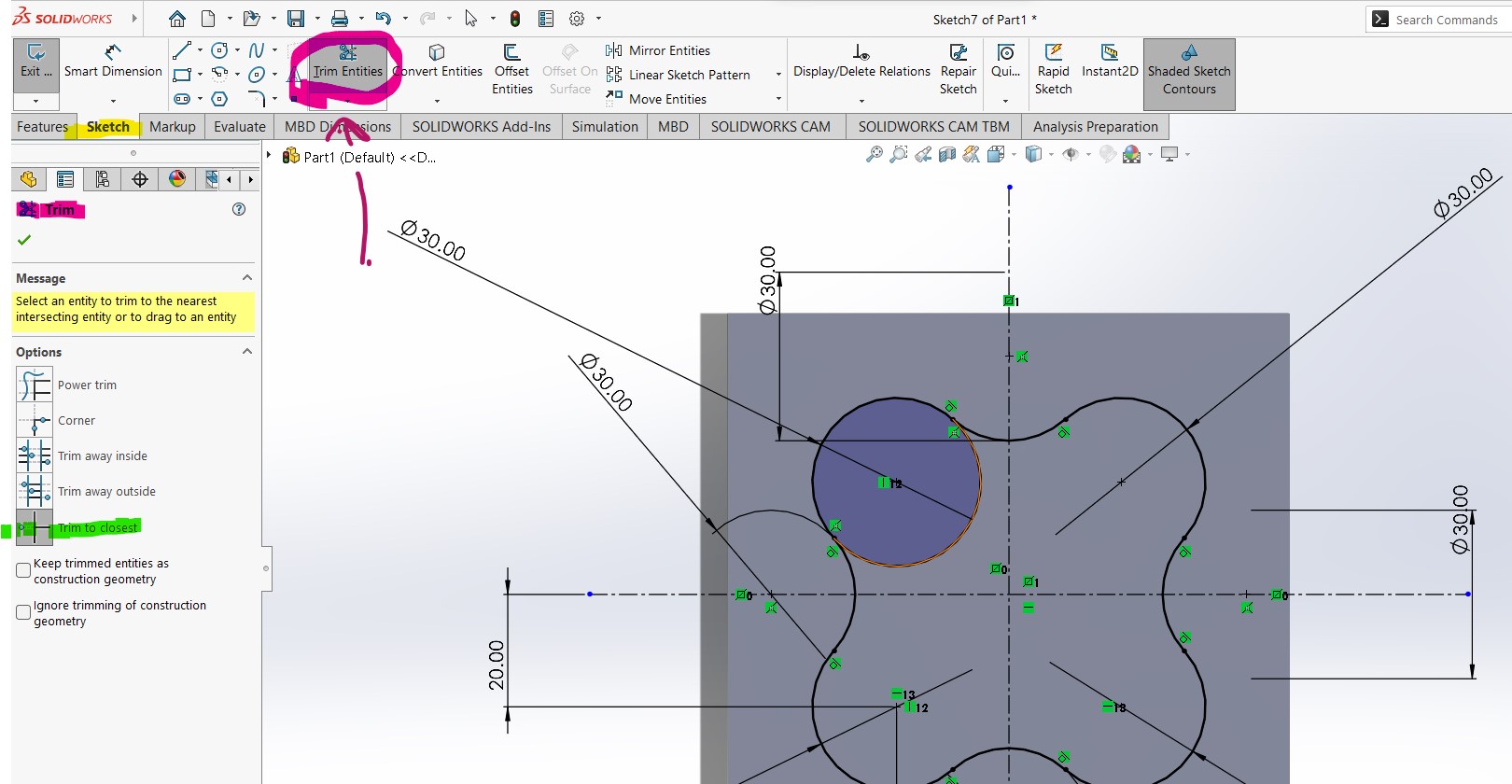
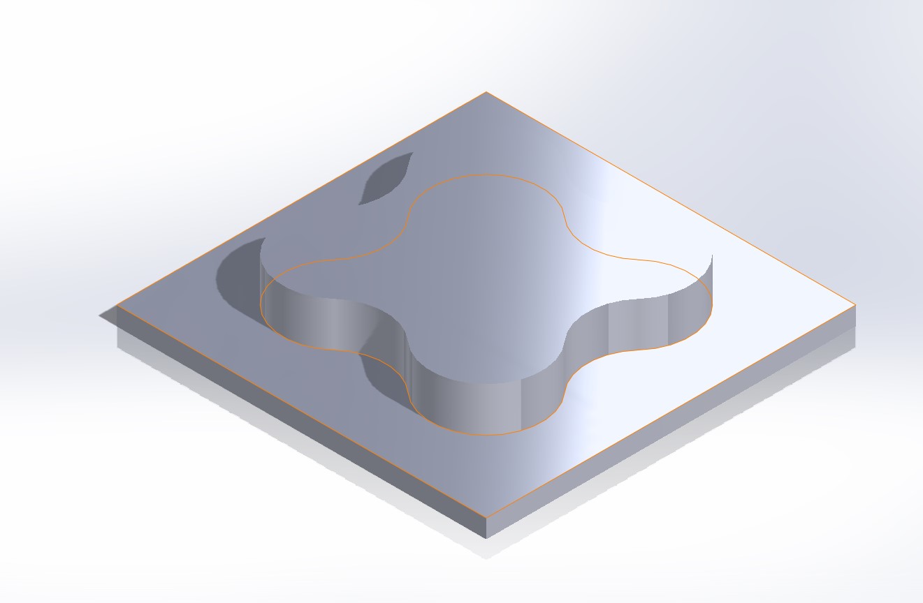
Finally we have something like this
Catia
Probably catia is the more uglier than solidworks, for my its less interactive but at the same time once you understand where is each tool is more easier to do tasks. Since my first year studing mechatronic engineer i started desgin on Catia, i took more time to learned it but now probably its the desgining software more complete for me.
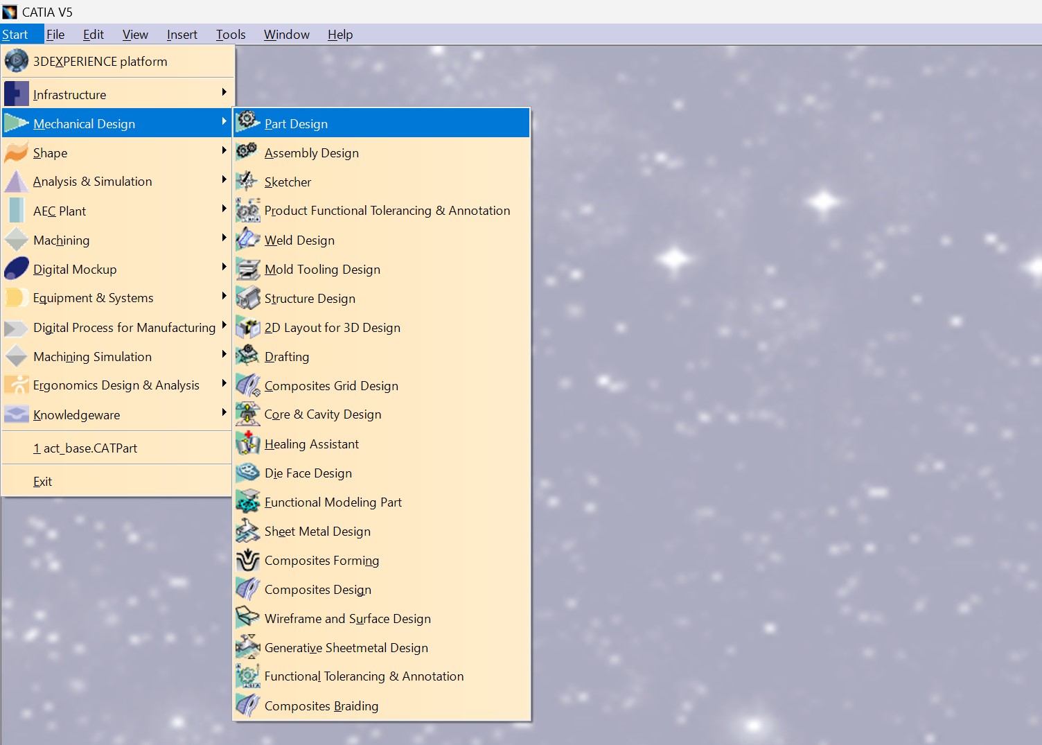
Up next, I'll demonstrate how to create a Part design file in Catia.
Start > Mechanical Design > Part design > name of the part
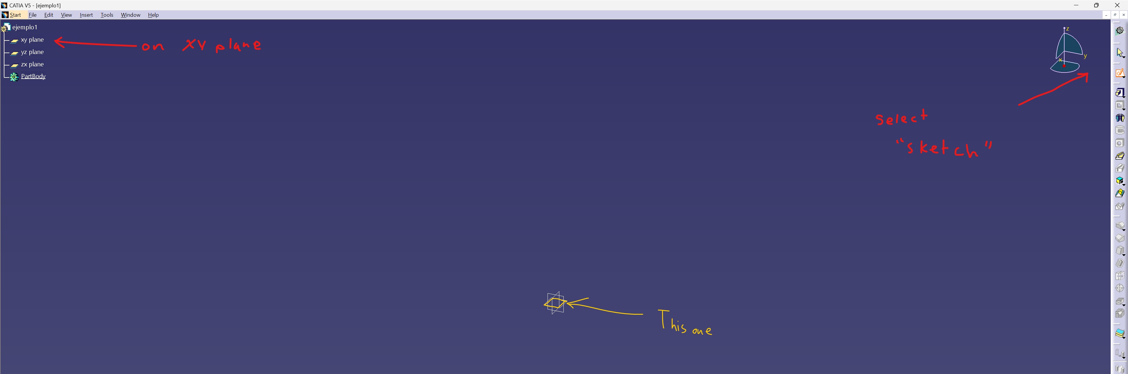
To create a skecth (where you'll draw ) follow the next example
Click on Sketch tool > Select your plane
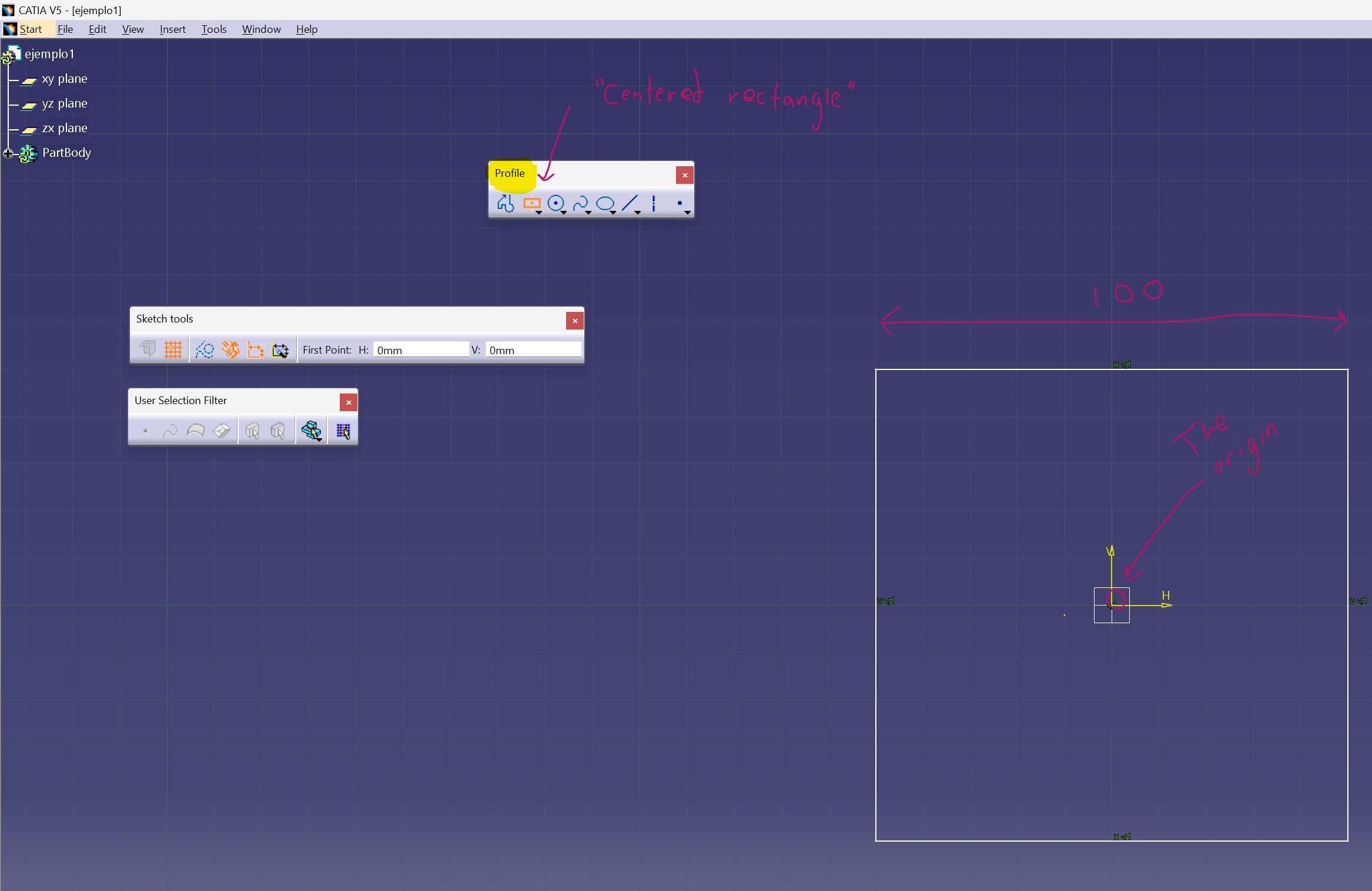
Go to Profile tools > Centered rectangle > choose the origin of the rectangle the same as the plane
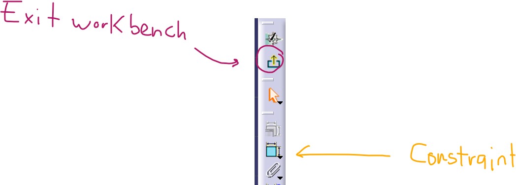
to go out of the skecth
In your right side bar, you'll see the next thing, click on exit workbech
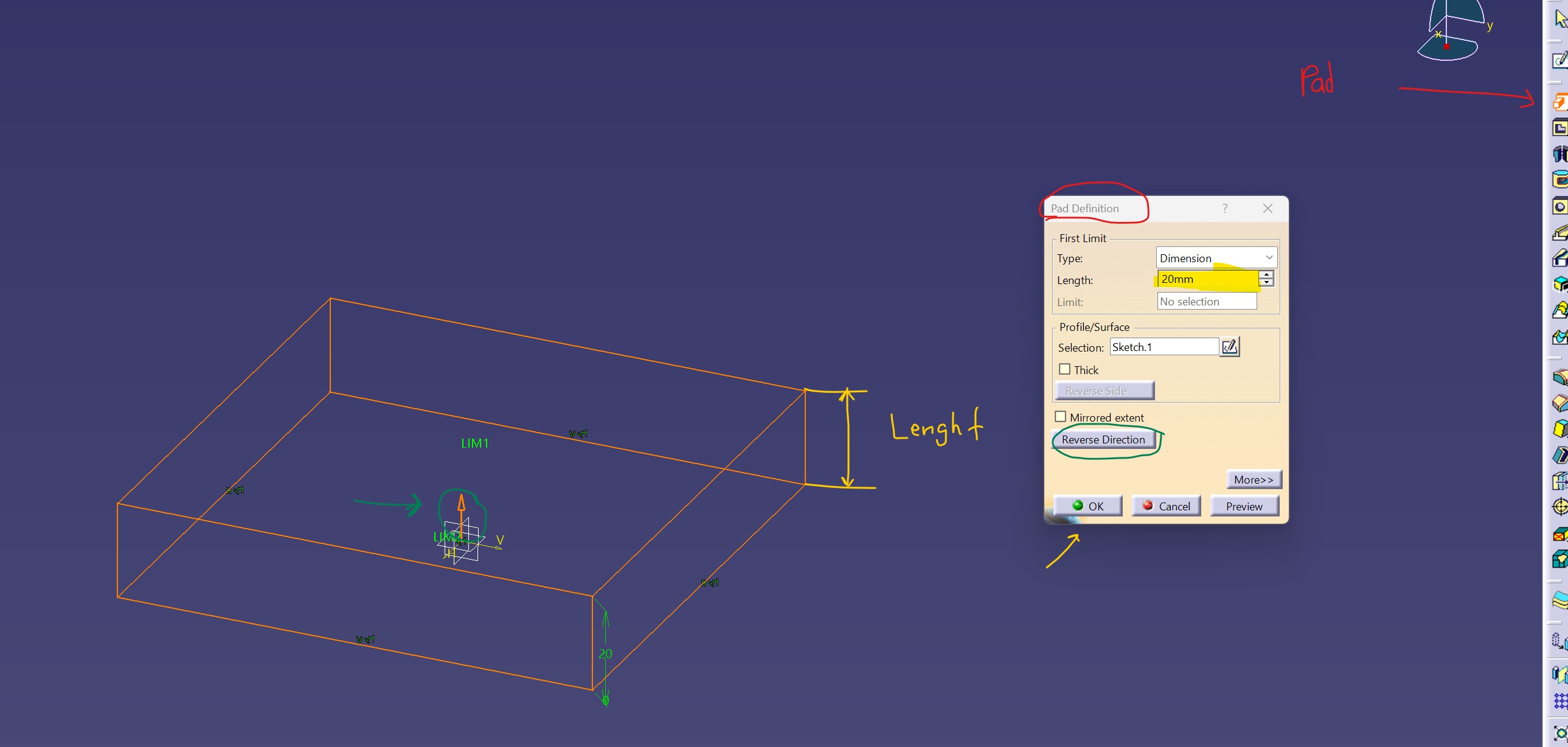
We have a 2D design but now we need to convert into 3D for that select Pad definition and modify the lenght you need.
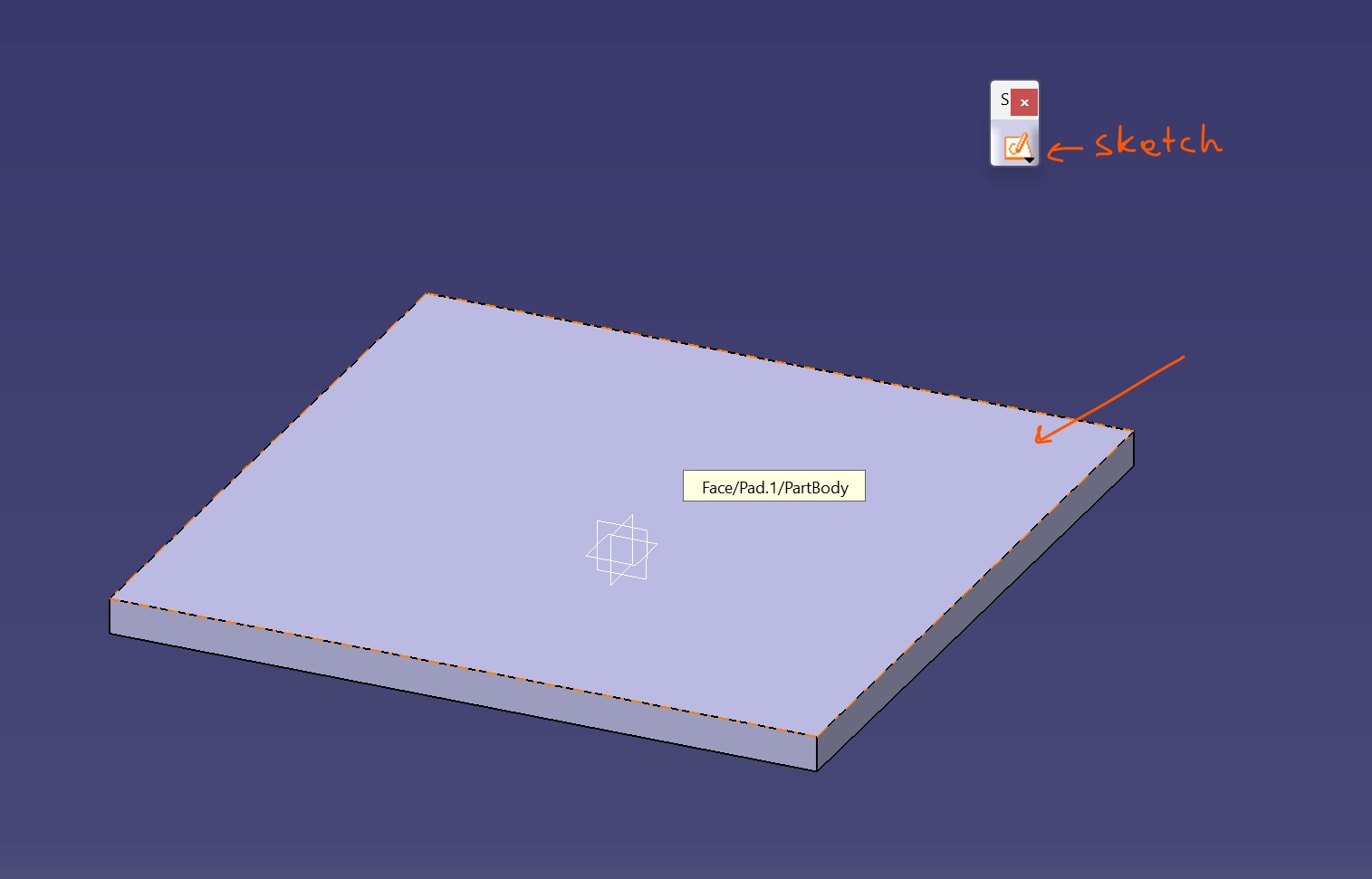
In the first steps i spoke how to create a sketch on a plane, but now if you need to create a new sketch to agregate something above, its necesarry to create a new one on the Part.
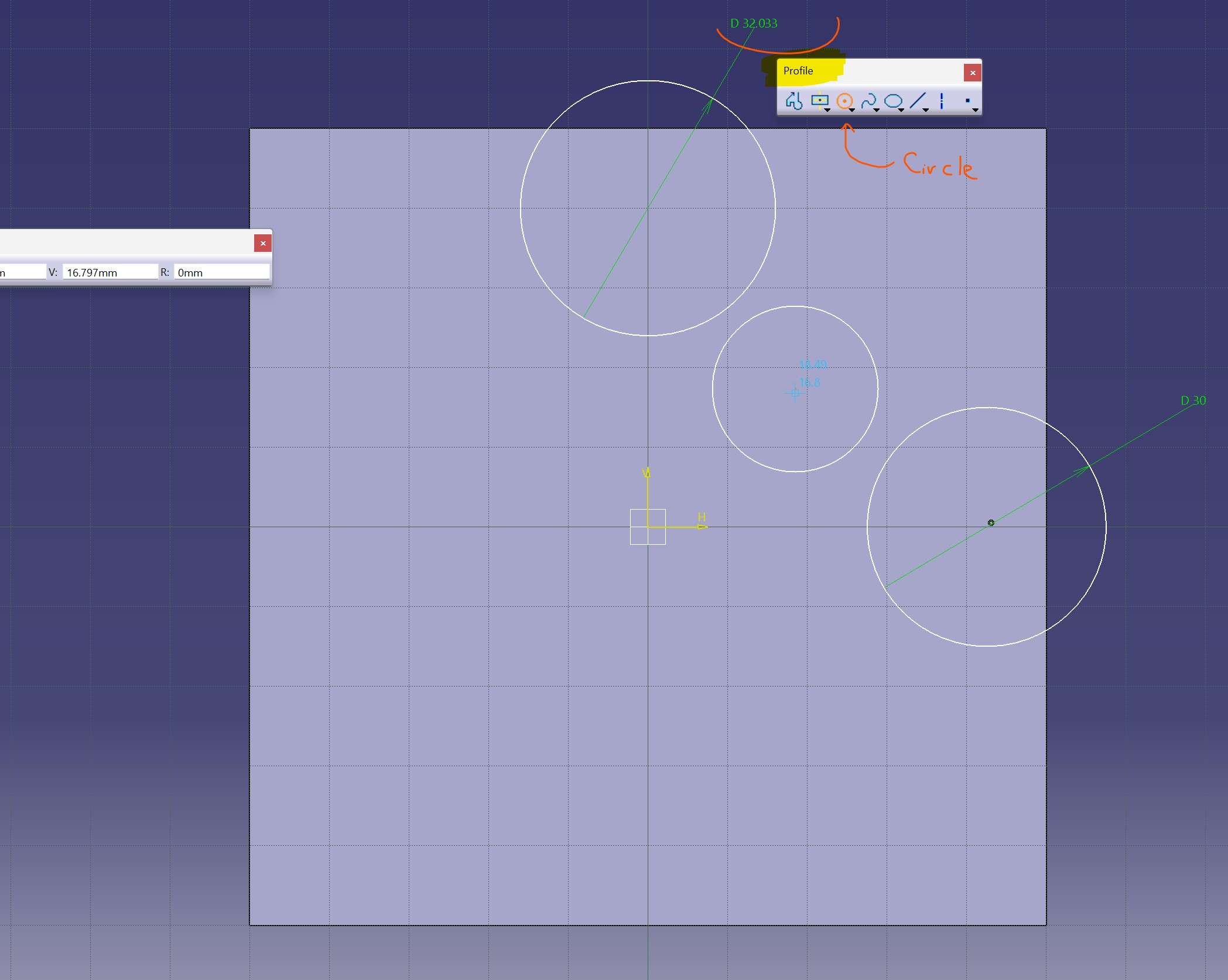
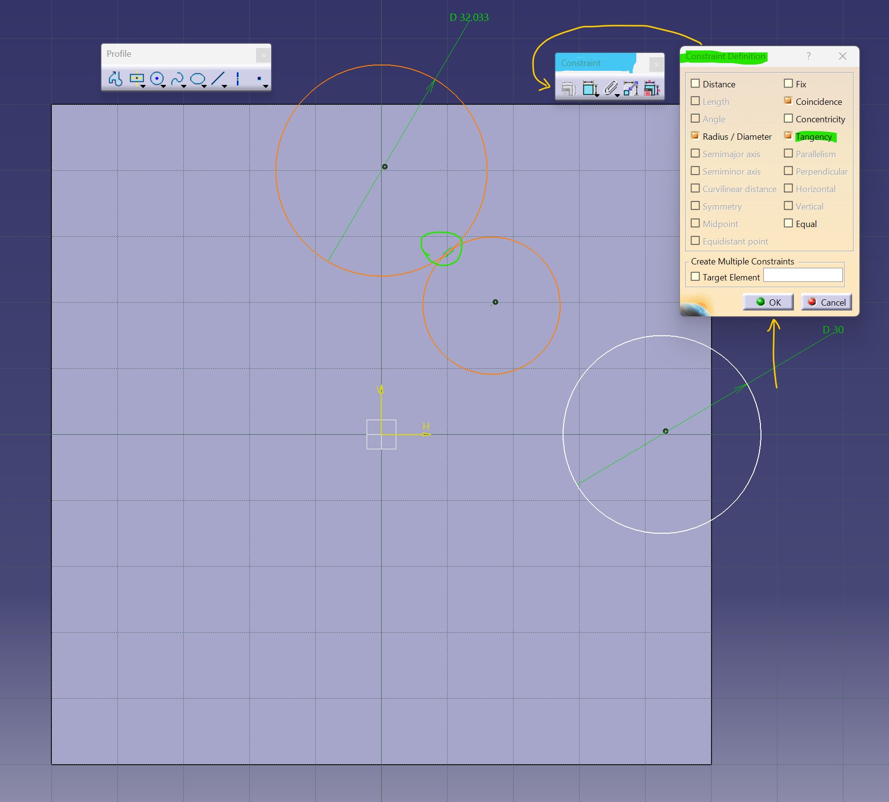
Above there, i draw 3 circles of 30 mm diameter
Following the plane, its necesary to have those circles together, what i want to do its apply the mirror tool across the 2 axis, one to duplicate the first block of the square into the left. Once we got the top side we'll duplicate into the button part.
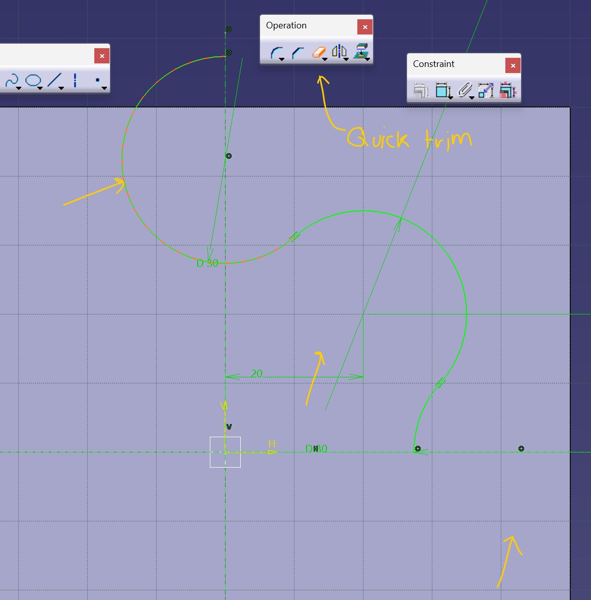
I create 2 geometry axis across the X line and Y line for be able to use the mirror tool.
Quick trim its a tool for erase a line on the sketch, but practically this tool works if you only want to delete it until the next line
In the following two images i applied mirror exactly how i described before
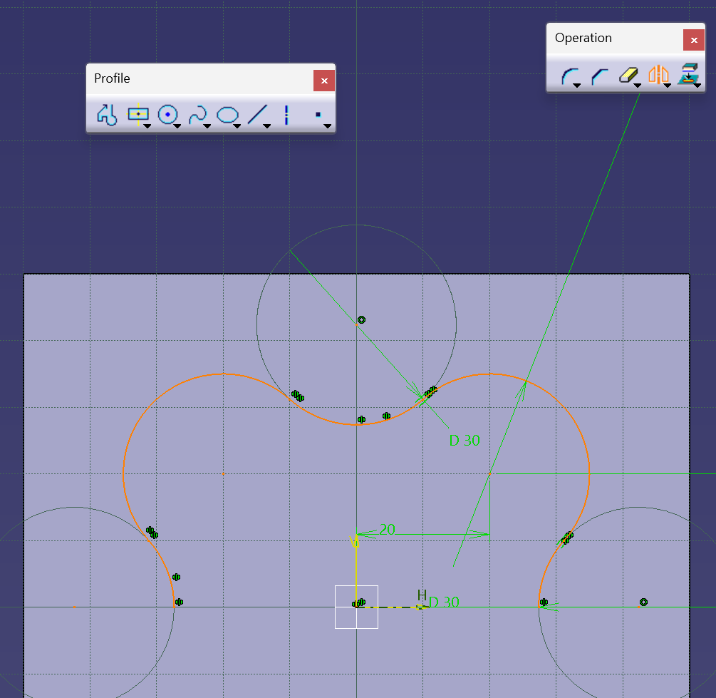
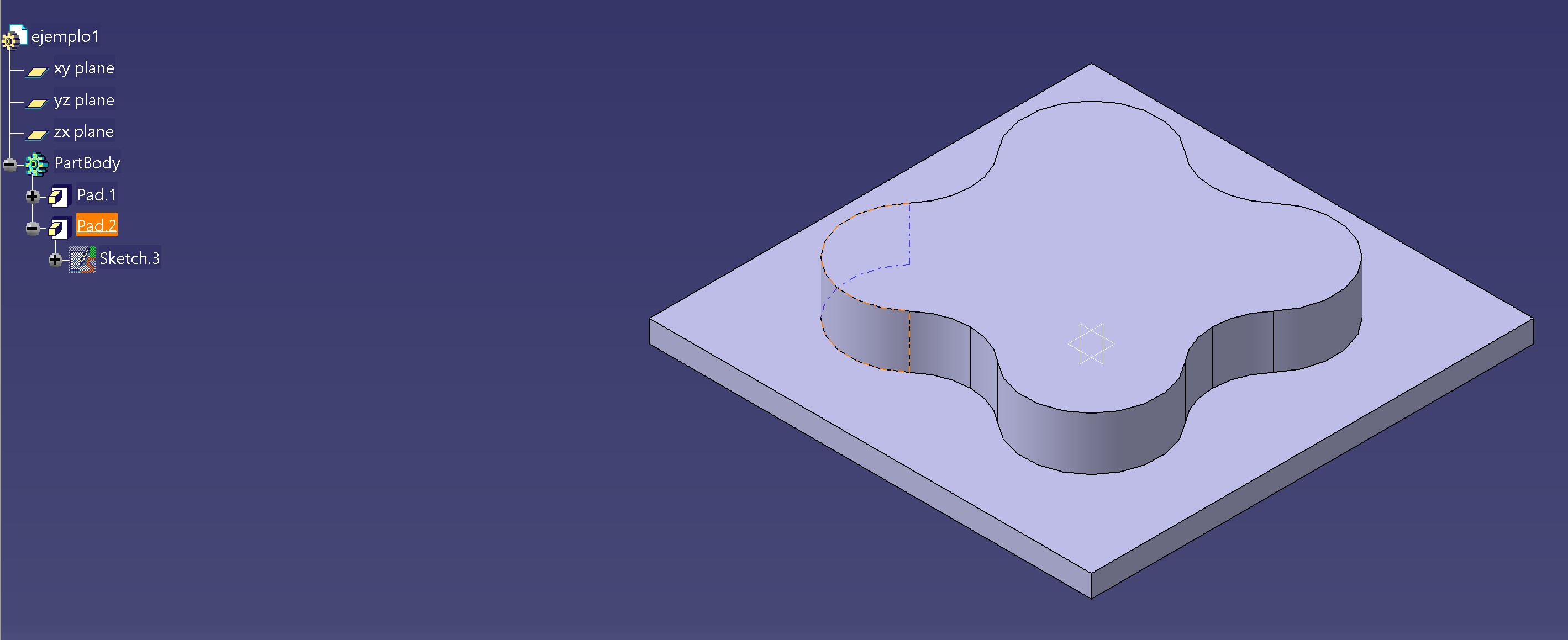
Finally once i finished the sketch you'll see all the lines on green, it will mean the sketch its closed and you can Pad
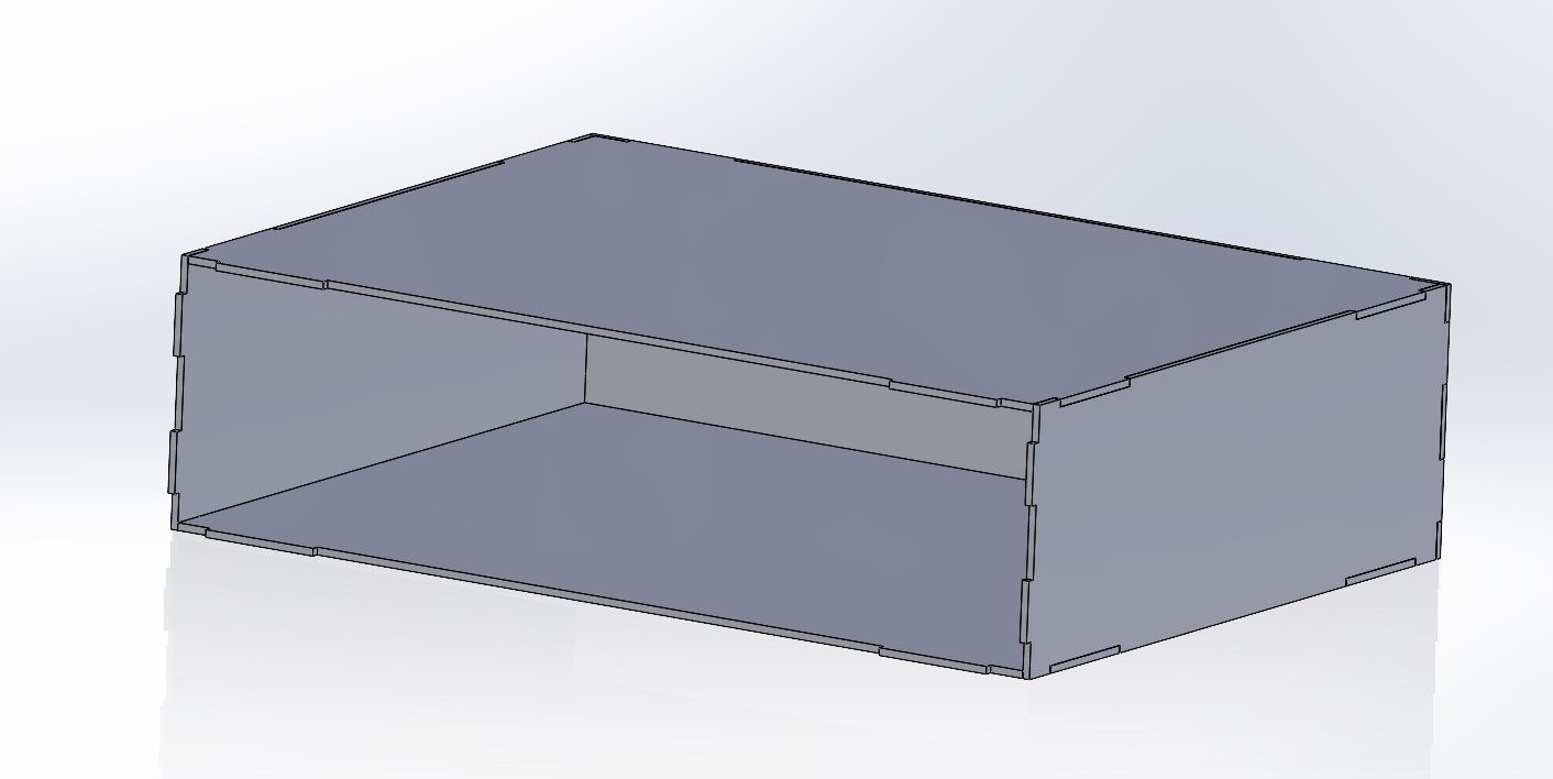
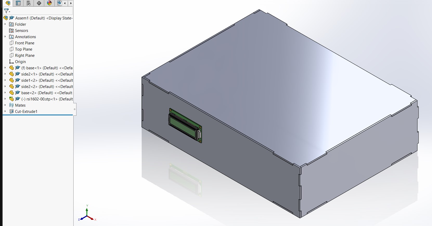
Finally design
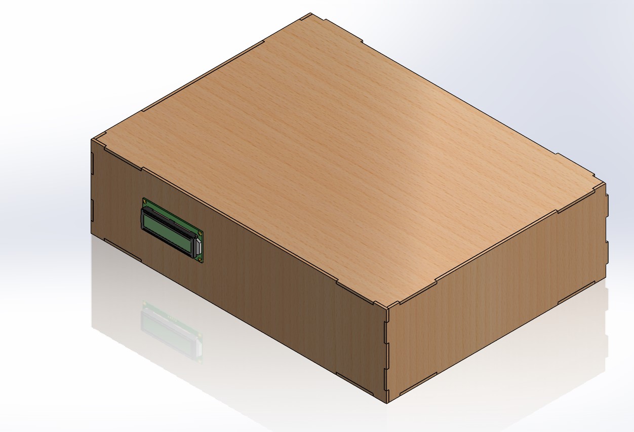
Render
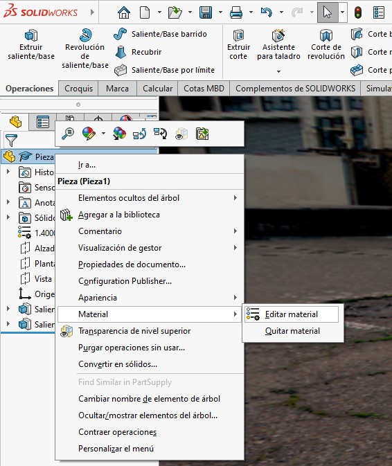
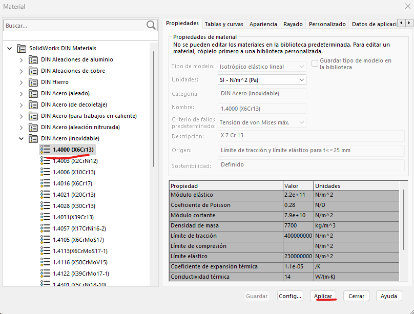
In addition to the CAD design, I added a section where I explain a bit about the rendering function in SolidWorks. The first step was to right-click on the part and add a material to visualize its colors. In my case, I chose stainless steel, but it could be any material you want, and then I clicked Apply.
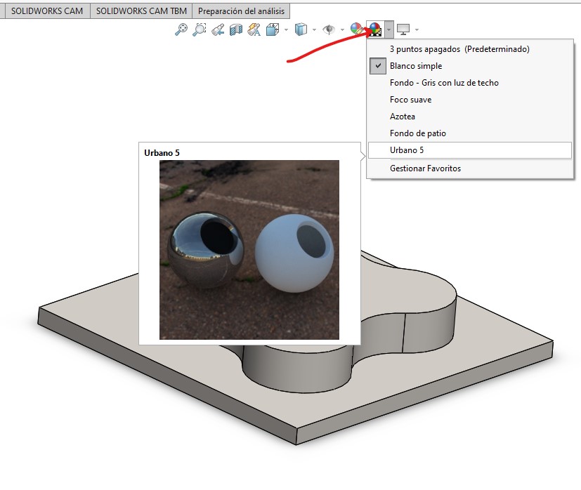
Then, in the top bar of the part, I looked for the icon with the colored sphere. This function is used to place the scene behind the part. By default, it comes with simple white, and I changed it to Urban 5.
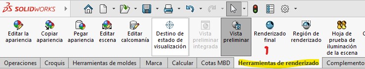
We go to the "Render Tools" section in the toolbar and click on Final Rendering.
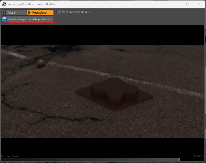
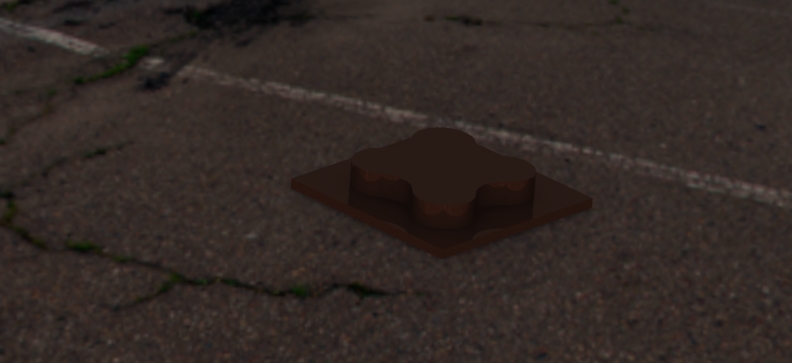
Finally, we save the image from the preview, and we obtain the following image where we can visualize what it might look like in reality.
Download files
Inkscape
Last time i use photoshop was in junior high school xd.
Using an IA, i got the following image, and i will try to scale and draw with illustrator and Inkscape

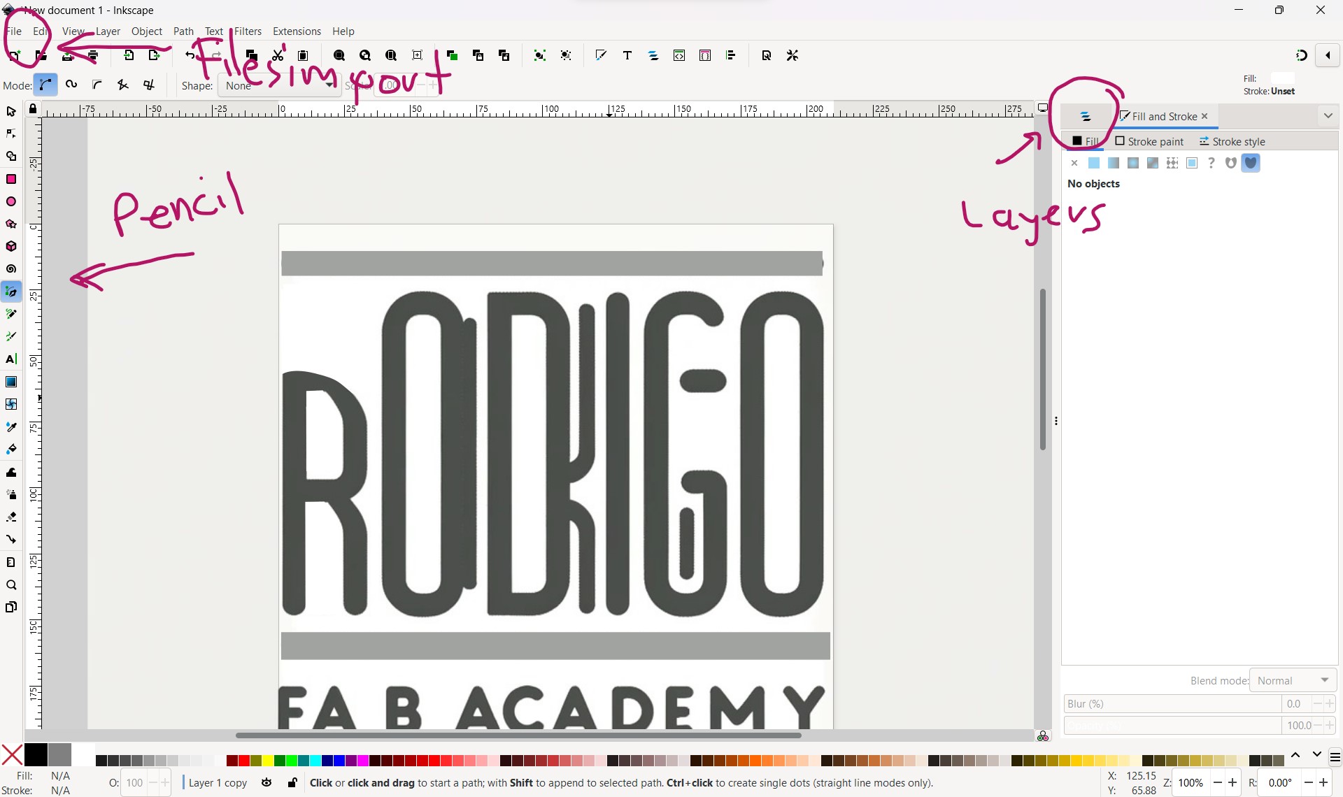
For desgin in 2D i used Inkscape software, where at the beginning was very diffcult for me to understand it so i watched a video tutorial, in this case i already had the logo generated by chat gpt, so in this programm i imported for copy the image and modicated a liitle bit different, change the color of the bars, erase things that i didnt like it and play around with the tools in the left side bar.
At the end i obtained the following image. I will make another example to have more options to choose which will be my permanently logo

Pixlr Editor
Basically i did the same thing, i ask chat gpt for a logo, and in base what i got from it i tried experimenting with this programm online. In my opinion its more easier to understand than Inkscape but obviously it has less tools. This is the image i got it :
In Pixlr i learned the Clone plug Tool, and i used a lot of trim, its the only two tools i worked for editing my logo.
Gimp
I also used the GIMP software, since it is free and several people had told me it was very easy to handle and understand. In my case, I did have to spend an hour to familiarize myself with the tools and understand what each one did. As a first step, downloaded an image of the Piltover logo, a city from the stories of League of Legends.

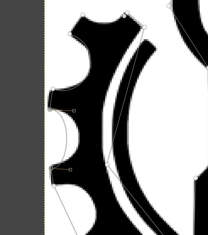
After that, I used the Paths Tool to basically do everything and selected the polygon option. What I understood is that I had to draw lines from one point to another, and wherever I wanted to create depth to align with the curves, I would click in the middle of the line where I wanted to make a curve, and it could be deformed to my liking.
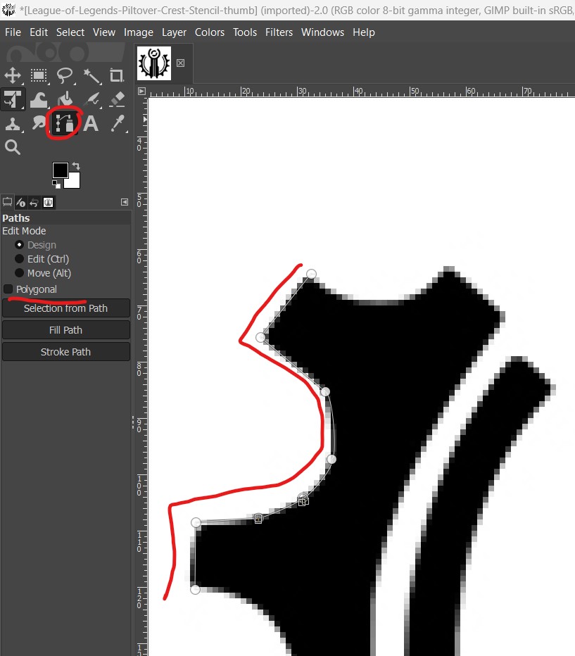
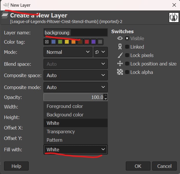
I had to select a background color, since it starts without a background. This color was added on a new layer and set as shown by the red arrows.
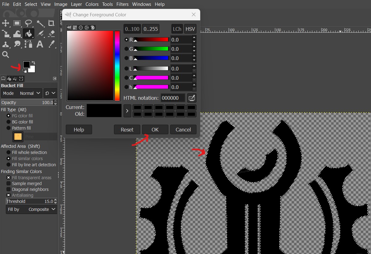
In the end, you create the layer as previously mentioned and set the color you want. In my case, I edited it to red.
Basically, what I did was trace a pre-existing image and tried to draw it as similarly as possible using the Paths Tool. Here you can see a comparison.

Comparation

Download files
Spectrophotometer case