Networking and Communications
Click here to see the group assigment
This is the Jumpers Time!
For this exercise, I used the Quentorres PCB and my PCB from Week 8. Cut another small PCB to connect 3 boards. I think this system could be ideal for my final project, since I want the garment to have a movement system on each shoulder.
I2C PROTOCOL Communication
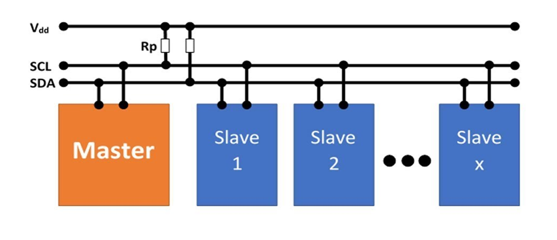
Inter-Integrated Circuit, or I2C for short, is a popular serial communication standard.
It lets devices that are near to one another or other integrated circuits on the same circuit board communicate with one another using just two bi-directional lines: Serial Data (SDA) and Serial Clock (SCL)
The protocol can function in either Master or Slave mode, with one or more Master devices controlling the
flow and initiating communication and one or more Slave devices carrying out commands. I2C data transmission is
organized into packets of nine bits, which include an address frame, data bits, and control bits for error handling
(ACK/NACK). I2C has advantages over other protocols, including strong error detection through ACK/NACK signaling,
cost-effectiveness, and multi-master capabilities, despite its slower speed.
I2C is appropriate for applications needing dependable, low-speed serial communication within constrained environments.
I2C has two special ways of working with slaves. The Master can send data to the slave, or it can request data from the slave. After the address bit follows what is called an I2C read/write bit. If the master wishes to receive data from the slave it sends a read bit by bringing the line high.
How to use the I2C protocol
The I2C Software Protocol
Send a start sequence
Send the I2C address of the slave with the R/W bit low (even address)
Send the internal register number you want to write to.
Send the data byte
[ Optionally, send any further data bytes]
Send the stop sequence
First Thing's First
Let´s to prepare the Attiny to program with Arduino
If you don´t remember how to connect Arduino to the Attiny Click here!
SLAVE CODE
To configure the Attiny as a slave, we must load a code that indicates that it will be receiving information from a specific address and establish the action it will perform when it receives that information. In this case, when you press the MASTER button, the SLAVE will start to move the SERVO in a loop
Click to download code
		#include Servo.h // Servo.h entre los signos de menor que y mayor que
		#include Wire.h // Wire.h entre los signos de menor que y mayor que

		Servo raul; // Objeto para controlar el servomotor

		void setup() {
		  Wire.begin(0x10); // Iniciar la comunicación I2C como esclavo con dirección 0x10
		  Wire.onReceive(receiveEvent); // Configurar la función para manejar eventos de recepción I2C
		  raul.attach(D6); // Pin donde está conectado el servomotor (D6 en el caso de la placa)

		  // Puedes configurar aquí el ángulo inicial del servomotor si es necesario
		  // Por ejemplo, raul.write(0); para iniciar en 0 grados
		}

		void loop() {
		  // Puedes agregar aquí cualquier lógica adicional que necesites en el loop principal
		  delay(100); // Pausa para evitar lecturas excesivas de I2C
		}

		void receiveEvent(int bytes) {
		  if (Wire.available() >= 1) {
			int angle = Wire.read(); // Leer el ángulo enviado por el maestro a través de I2C
			// Asegurarse de que el ángulo esté dentro del rango de 0 a 180 grados
			if (angle >= 0 && angle <= 180) {
			  raul.write(angle); // Mover el servomotor al ángulo recibido
			}
		  }
		}
MASTER CODE
To configure the MASTER, we must load a code with the same address as the slave so that they can
communicate in addition to all the movement instructions that the Attiny Outputs will carry out.
In this case, while the button is pressed, the Attiny will begin to move the servomotor from 0 to 180 degrees in an infinite
loop that will only stop until we stop pressing the button.
Click to download code
#include Wire.h // Wire.h entre los signos de menor que y mayor que

	#define BUTTON_PIN A1  // Pin del botón conectado al RP2040
	#define SLAVE_ADDRESS 0x10  // Dirección I2C del ATtiny como esclavo

	bool communicationActive = false;

	void setup() {
		Wire.begin();  // Inicia la comunicación I2C como maestro
		pinMode(BUTTON_PIN, INPUT_PULLDOWN);  // Configura el pin del botón como entrada con resistencia de pull-down
	    }

	void loop() {
		// Verifica el estado del botón para activar o desactivar la comunicación
		if (digitalRead(BUTTON_PIN) == HIGH && !communicationActive) {
		// Si se presiona el botón y la comunicación no está activa, inicia la comunicación
		communicationActive = true;
		startCommunication();
	  } else if (digitalRead(BUTTON_PIN) == LOW && communicationActive) {
		// Si se suelta el botón y la comunicación está activa, detén la comunicación
		communicationActive = false;
		stopCommunication();
	  }

	  // Si la comunicación está activa, realiza las operaciones de control del servomotor
	  if (communicationActive) {
		moveServo(SLAVE_ADDRESS, 0);  // Ejemplo: mueve el servomotor a 0 grados
		delay(1000);  // Ejemplo: espera 1 segundo entre movimientos
		moveServo(SLAVE_ADDRESS, 180);  // Ejemplo: mueve el servomotor a 180 grados
		delay(1000);  // Ejemplo: espera 1 segundo entre movimientos
	  }
	}

	void startCommunication() {
	  // Puedes realizar acciones adicionales al iniciar la comunicación, si es necesario
	  // Por ejemplo, inicializar variables, enviar comandos de inicialización, etc.
	}

	void stopCommunication() {
	  // Puedes realizar acciones adicionales al detener la comunicación, si es necesario
	  // Por ejemplo, enviar comandos de apagado, liberar recursos, etc.
	}

	void moveServo(int address, int angle) {
	  Wire.beginTransmission(address);
	  Wire.write(angle);
	  Wire.endTransmission();
	}
How it works the XIAO RP2040 when program them
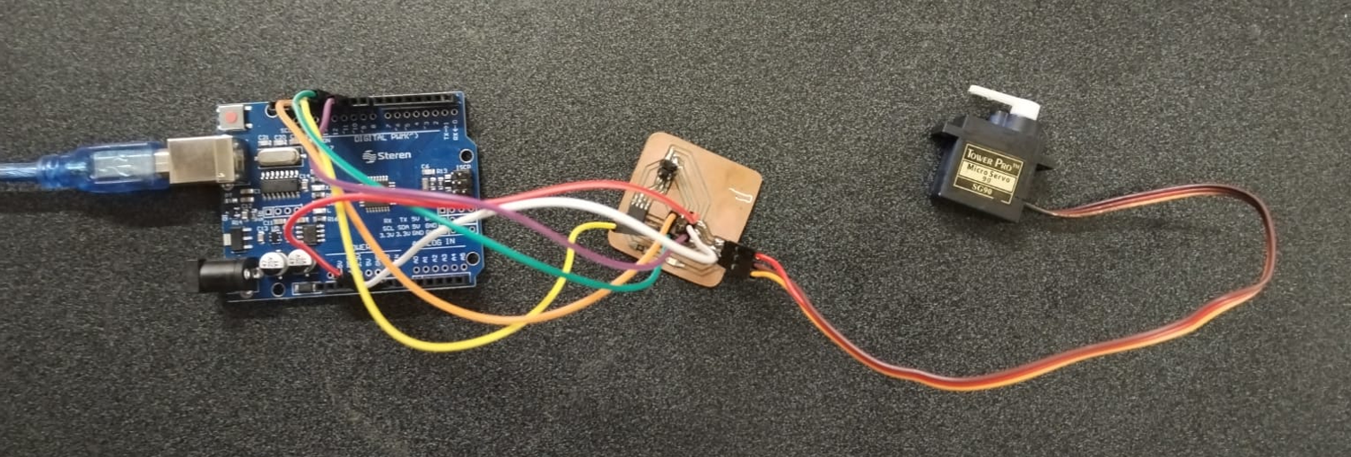
Let's try with one servomotor
How we expand communication
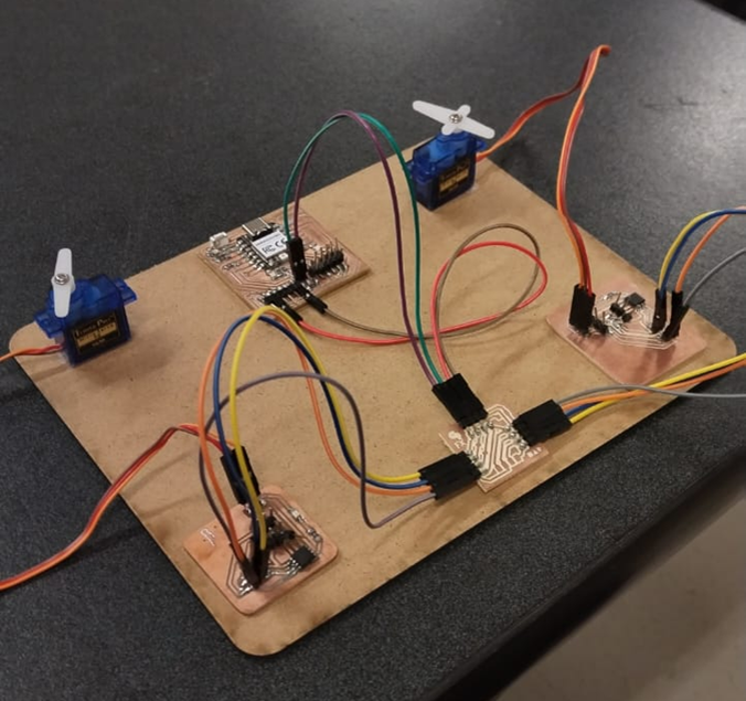
Let's try with more servomotors
NOTE: For this exercise I used the same code for the master and uploaded the same slave code for the second Attiny
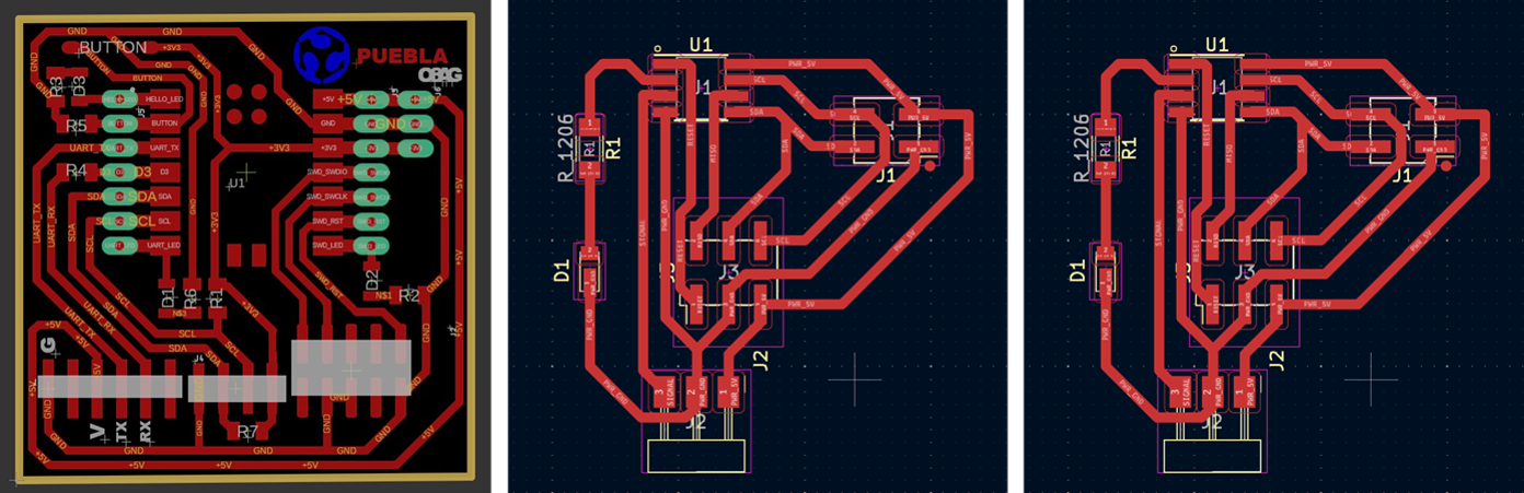
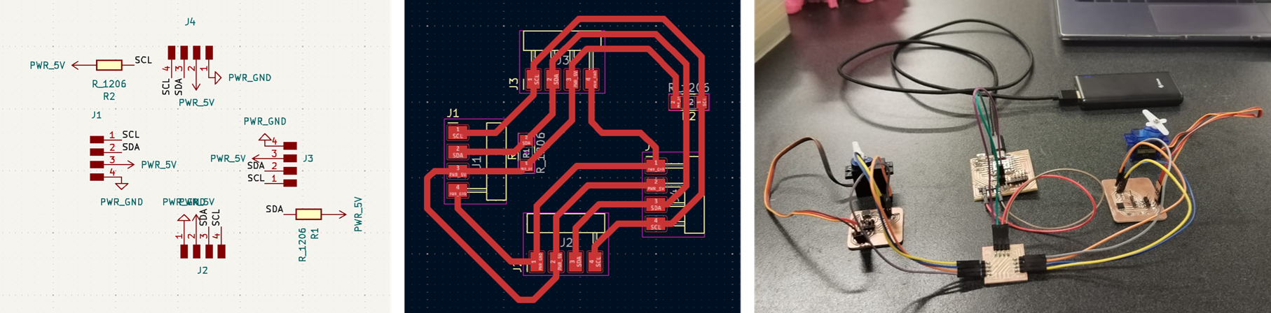
The Quentorres PCB only has one output for SCL and SDA, so to extend the communication to other PCBs,
I made a power distributor. I designed a board with 4 4-pin outputs (SDA, SCL, GND and Voltage) with their
respective resistors. That way, I was able to connect the other Attiny that I had previously configured with the same slave code.
So, when you press the MASTER button, both servomotors will start moving at the same rate.
I placed the entire system on a wooden plate to better visualize the connections and since the Quentorres was configured as MASTER,
the only thing I did was connect it to a power source for the system to work. (I used a 2500 mah power bank)
It worked!
I'm ready to integrate it into the final project