Mechanical Design
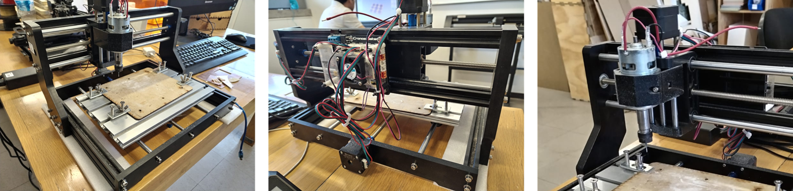
Look at that, it´s a CNC!
Inspiration at first sight
I took as a basis the design of the structure of the Fab LAb milling machine
I did all the design using SolidWorks
- we decided to use 15 mm MDF and cut the mirrored design to glue them and reach a thickness of 30 mm.
- I took the measurements of the milling machine and made a plan with the pieces considering the Kerf cut
- We drilled the holes to trap the structural tubes. In the extrusion of each piece, you can see the difference in thicknesses in the perforations.


If you want to download the files
Click here to Design in SolidWorks
Click here to Assembly in solidworks
I prepared the VCARVE File
It was necessary to create a recess for the whole, an external cut for the large pieces and an internal one for the perforations.
The assembly
To the assembly Isaac and Isaac did a very good job cutting the piece and adding some details for the assembly with the metal parts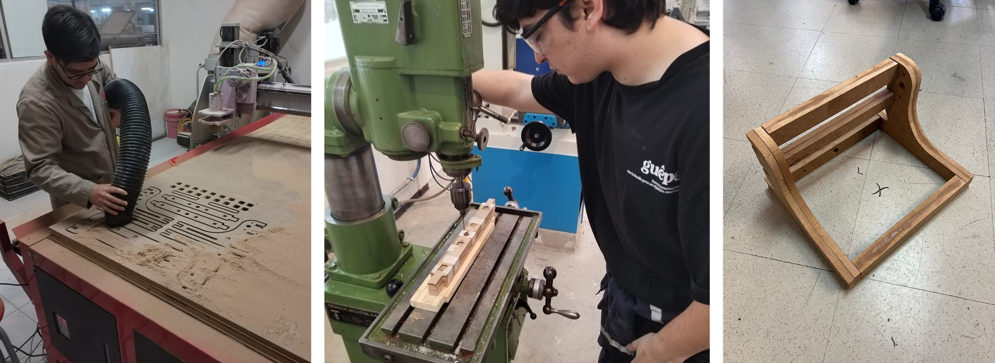
The final result
Click here to see full project