CNC manufacturing
For the last three weeks I have been working with my team on the manufacture of a CNC machine. CNC stands for Computer Numerical Control. A CNC system is a manufacturing process where a computer controls the movements of machinery and tools through numerical input. These systems are widely used in various industries, including manufacturing, woodworking, metalworking, and more. In a CNC system, a computer translates designs created using CAD (Computer-Aided Design) software into numerical code, often called G-code. This code contains instructions for the CNC machine on how to move, cut, shape, or otherwise manipulate the material being worked on. CNC machines come in various types, including CNC mills, lathes, routers, plasma cutters, and more. Each type of machine is specialized for different applications, such as cutting, drilling, carving, or shaping materials like wood, metal, plastic, or composites. The advantages of CNC machining include high precision, repeatability, automation of manufacturing processes, and the ability to produce complex shapes and parts with relative ease. CNC technology has revolutionized manufacturing by improving efficiency, reducing labor costs, and enabling the production of highly customized and intricate components.
Stages of the process
I will describe the manufacturing process according to the stages in which I participated: Stage 1: idea & design Stage 2: component evaluation and parts reuse Stage 3: 3D pieces & structure design Stage 4: assembly and control
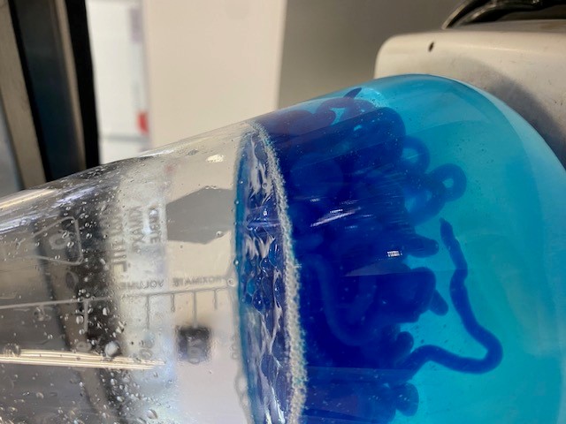
1. Idea & design Brainstorming was difficult because each of the team members has different professional profiles. 1. The first idea that I proposed was to make a pasta cutter, since making pasta is a very artisanal process and I thought it could be an attractive idea. 2. printing of biomaterials, I told you what I do with biomaterials and the development of them using agroindustrial waste. I showed them the materials I have made with hydraxyapatite, collagen, alginate, gelatin, fibers, etc. Most of the team decided to work with sodium alguinate to make a hydrogel. At first we wanted the alginate to dry only due to loss of moisture, but I mentioned that this at room temperature takes a long time (at least a week) and I mentioned that the 3D printer we would design would require a large amount of air. I proposed to them to make "gummies" by printing a solution of edible sodium alginate with flavor and color and fixing them instantly with a calcium chloride solution. I told them that in the laboratory a calcium chloride solution is used to immediately gel the solution and that the material has a gelatinous appearance, but firm so that it dries. At the beginning it was mentioned to put an impression bed that was a container into which the alginate solution would fall. But if the solution is placed and the sodium alginate material falls into the calcium chloride solution, it would detach and not have a defined shape. Image 1. Spherification is a process of forming spheres of a liquid. Spherification was originally developed in 1946 as a technique for creating flavor capsules or lipid-based ingredients. Today, encapsulation can be carried out using virtually any liquid. Encapsulation forms when calcium ions replace sodium ions and cross-links form between the alginate molecules, creating a solid gel that is thermally irreversible. Therefore, the design of the 3D printer was left with a solid printing bed in which a calcium chloride solution will be sprayed layer by layer of the print in order to generate the desired structure.
2. Component evaluation and parts reuse
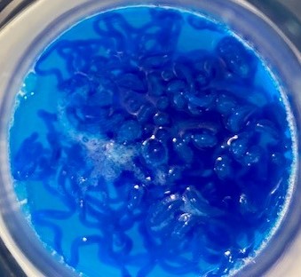
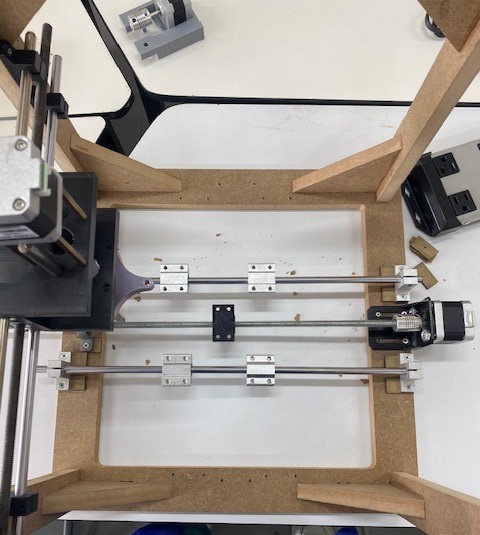
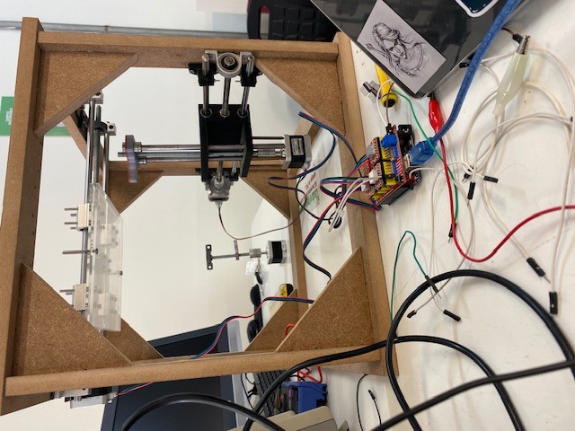
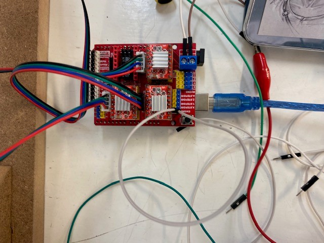
Structures of 3D printers (from suppliers and other students) were reviewed and parts of some were reused. The first thing was to complete all the parts (motors, screws, drivers, rods, screws, etc.). To control the air freshener with sodium alginate, we unmold a room freshener atomizer and try another atomizer. Image 2.


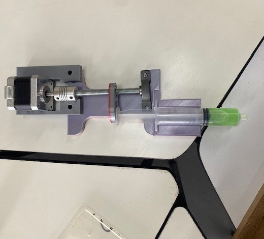
I did not help in the design of the parts such as the structure or the support for the atomizer.
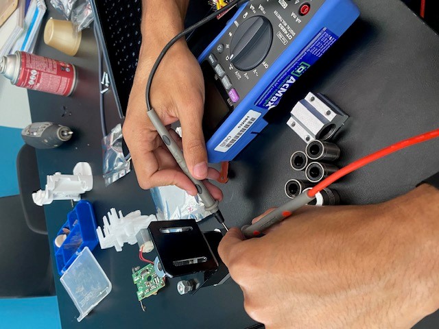
4. Machining
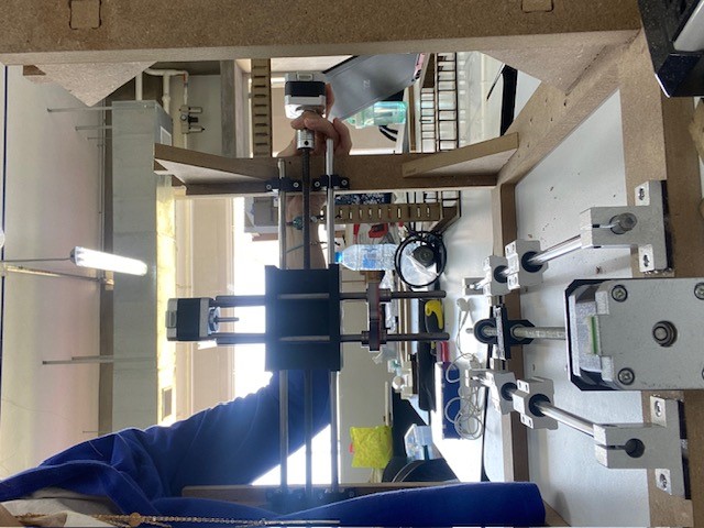
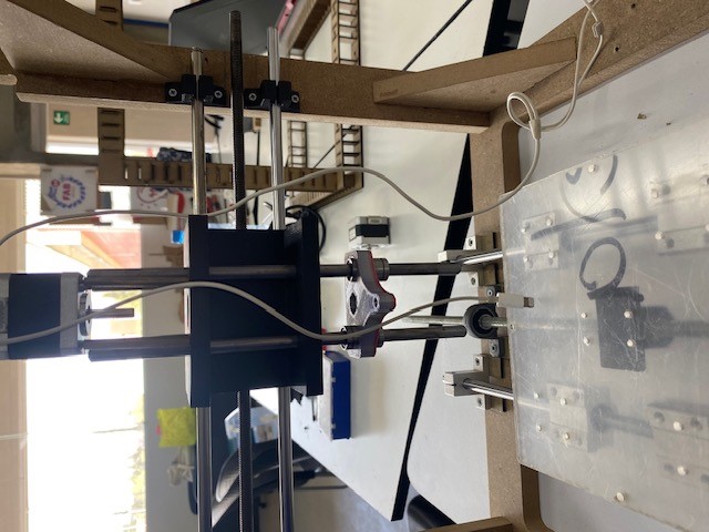
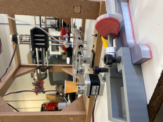
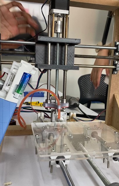
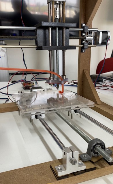
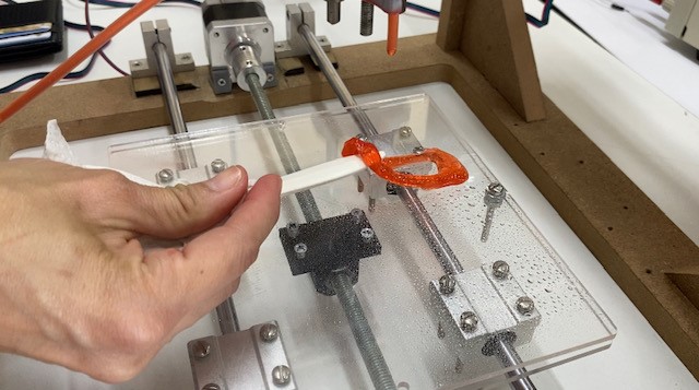
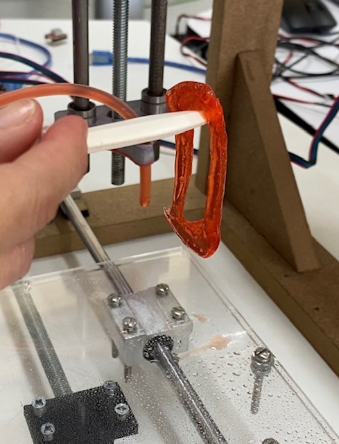
I helped with assembly of structure. Image 3


I helped with the interface design using figma.
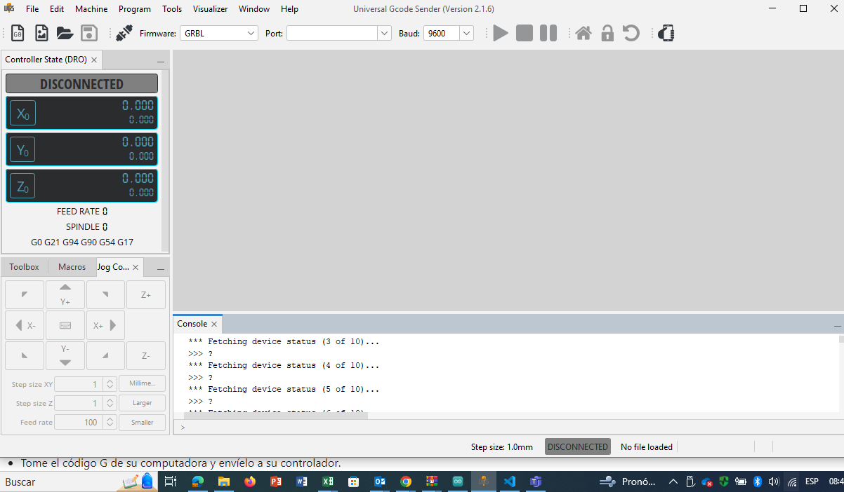
Several codes were tested to move the motors for Arduino, but in the end it was decided to work everything in Universal. The universal platform commonly used to program CNC (Computer Numerical Control) machines, including 3D printers, is called G-code. G-code is a language used to instruct CNC machines on how to move, position, and perform various tasks during the manufacturing process. It consists of a series of alphanumeric codes that represent specific commands, such as moving to a certain position, turning on/off a tool or extruder, adjusting speeds, and more. G-code is generated by slicing software, which takes a 3D model (usually in STL format) and converts it into a series of layers. Each layer is then further converted into G-code instructions that the 3D printer can understand. Slicing software allows users to customize various parameters such as layer height, printing speed, infill density, support structures, and more. Some popular slicing software programs used for generating G-code for 3D printers include: Cura: Developed by Ultimaker, Cura is an open-source slicing software widely used in the 3D printing community. Slic3r: Another open-source slicing software that offers advanced features and customization options. PrusaSlicer: Originally developed for Prusa Research printers, PrusaSlicer has become popular due to its user-friendly interface and powerful features. Simplify3D: A commercial slicing software known for its advanced capabilities and support for a wide range of 3D printers. OctoPrint: While not a slicing software itself, OctoPrint is a popular open-source web interface for 3D printers that allows users to upload G-code files, monitor prints remotely, and control their printers. These slicing software programs typically support a variety of 3D printers and can generate G-code tailored to specific machine configurations and user preferences. G-code files generated by slicing software are then transferred to the 3D printer either via USB, SD card, or through a network connection, depending on the printer's capabilities. There were some inconveniences in moving the engines that were resolved with engine tuning and some minor modifications to the structure. The appropriate library to run the 4 motors of the designed 3D printer was:
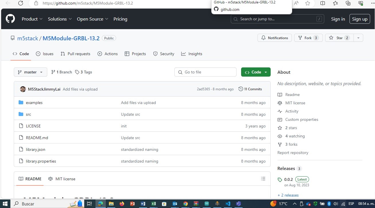
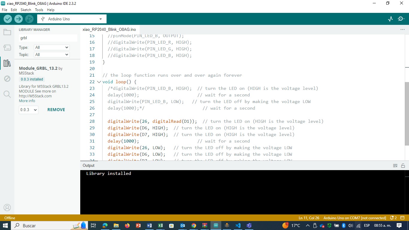
The link to download librery Universal library
Consultation pages and videos:
Universal G code troubleshooting
Universal G code connecting controller
Universal G code configuration
Results
Conclusion
Teamwork is always complicated due to the different profiles of the members and the work times, but I think we all collaborate a little and focus on finishing the activity. I learned about the mechanism of 3D printers, about the applications to design and make interfaces work. I met Universal, and although there are a large number of options and libraries to coordinate the 3D printer motors, it is not that complicated to use.