Embedded programming
What is an embedded program?
Embedded software refers to computer programs designed to run on specific hardware,
with the goal of controlling functions on devices. The difference with software is that these run on our computers
and embedded software is designed for specific tasks on embedded devices.
This week's task has several phases:
1. Engrave and cut PCB
2. Program the system
Some characteristics of these systems are
Specialization: Embedded software is specialized to perform specific functions on a particular device.
Resource Efficiency: Embedded devices have limitations in memory and processing power, so these must be used carefully.
Real Time: Embedded software operates in real-time environments, meaning it must respond to events within specific time limits.
Results
1. Engrave and cut PCB
Important information to consider before engraving and cutting the plate is found in
Minimum Clearance and Width
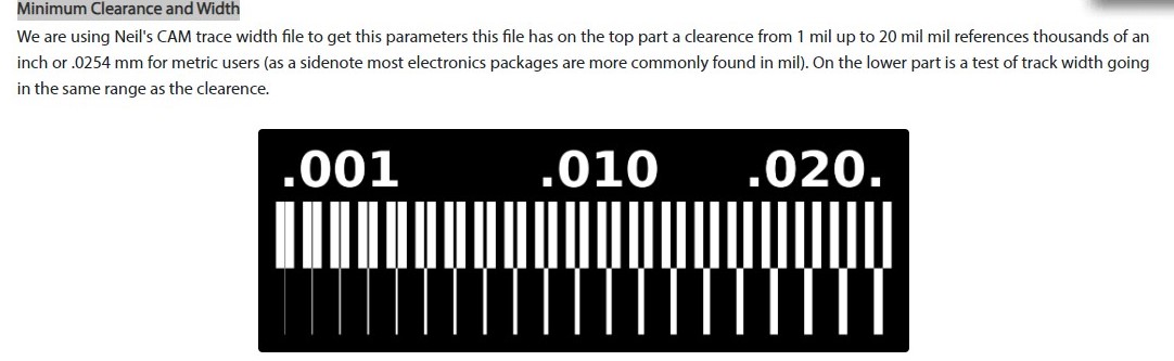 Image 1. Minimum Clearance and Width
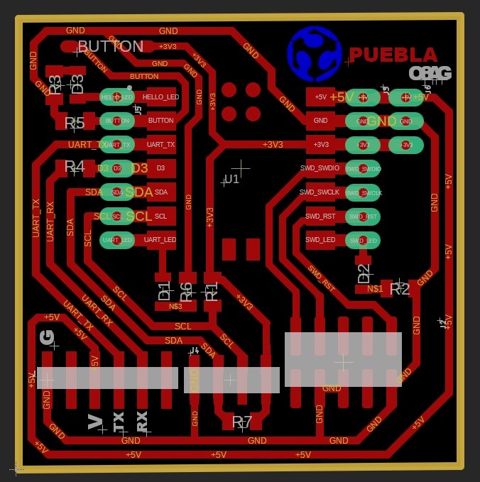 Image 1. PCB layout provided
To transform the image and be able to use the SRM-20 machine, you need to change the file extension and for that use the MODS program MODS
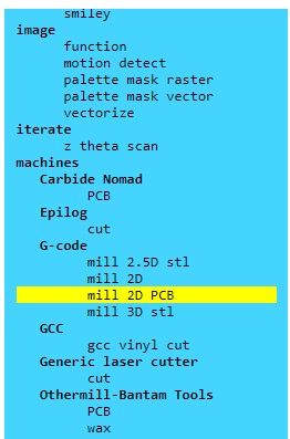 Image 2. Machine selection in the MODS program
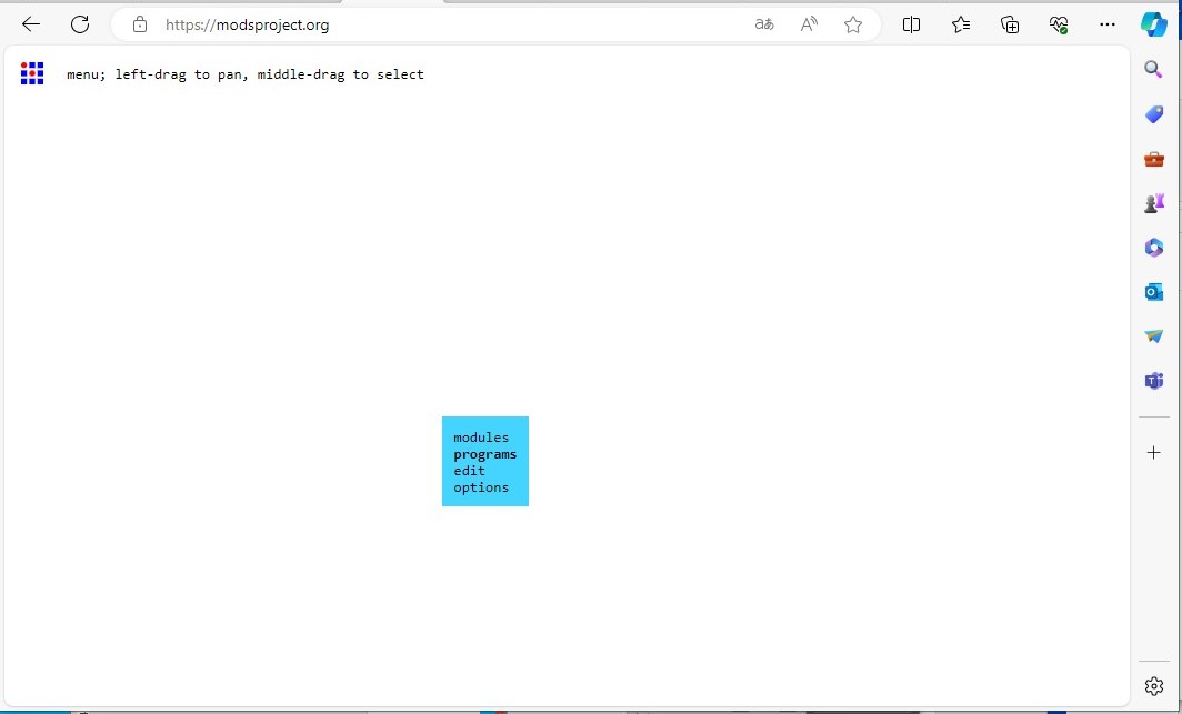 Image 3. Part of the path to convert the file
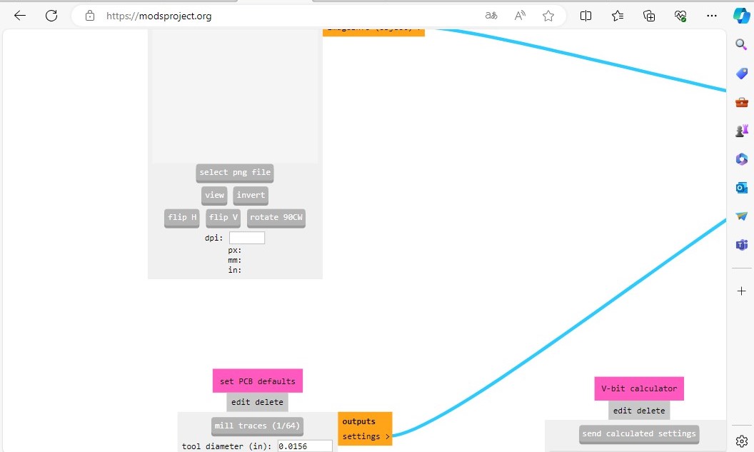 Image 4. Part of the path to convert the file
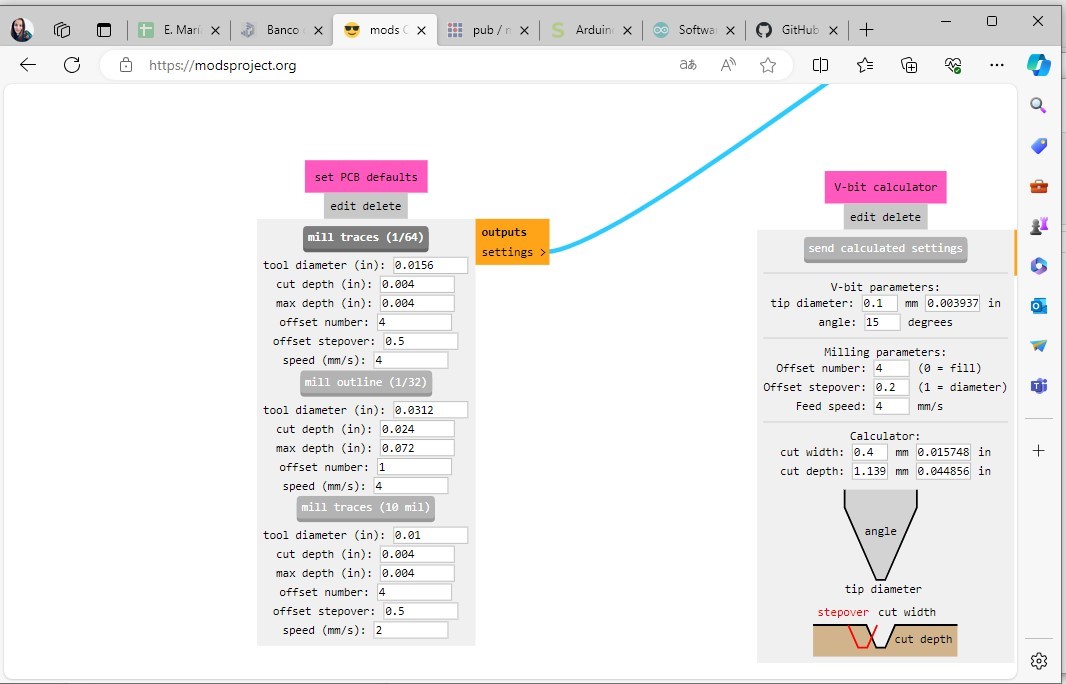 Image 5. Part of the path to convert the file
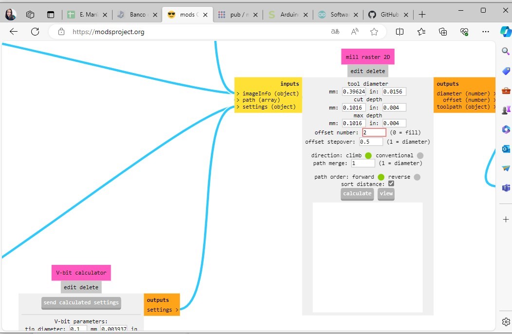 Image 6. Part of the path to convert the file
 Image 7. Part of the path to convert the file
 Image 8. Part of the path to convert the file
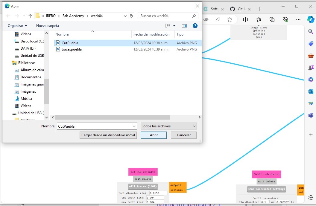 Image 3. Part of the path to convert the file
Image 9. Part of the path to convert the file
Image 3. Part of the path to convert the file
Image 9. Part of the path to convert the file
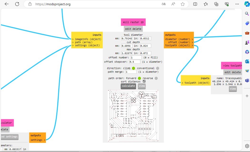 Image 10. Part of the path to convert the file
Engrave and cut procoees using SRM-20 machine
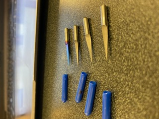
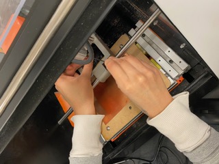
 Image 11.Engraving needle installation
 Image 12. Z axis adjustment
To cut the plate it is necessary to install another tool and make the z-axis adjustment
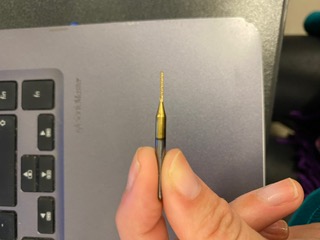 Image 13.Cutting tool
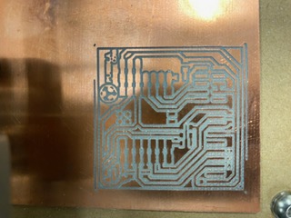 Image 14.Plate engraved

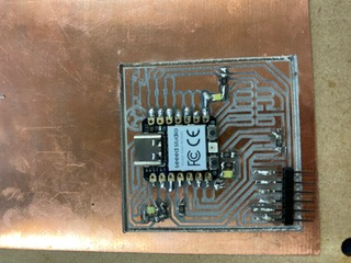 Image 15.Plate with soldered components
Once the plate was engraved, the necessary pieces were welded together.
2. Program the system
For this system, the Seeed Studio XIAO RP2040 was used, which is capable of supporting Arduino, MicroPython and CircuitPython.
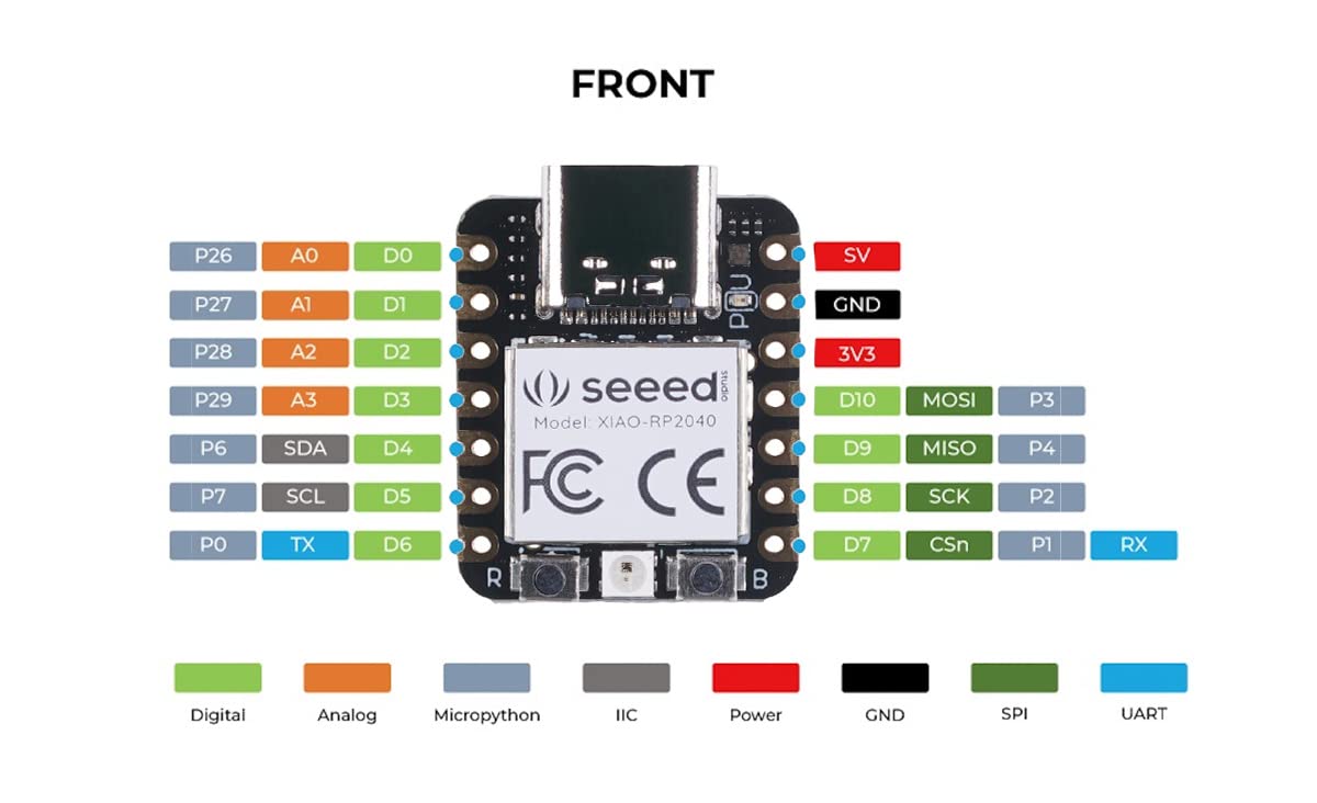 Image 16. To connect arduino with seeedstudio
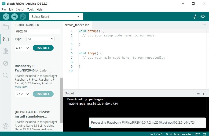 Image 17. To connect arduino with seeedstudio

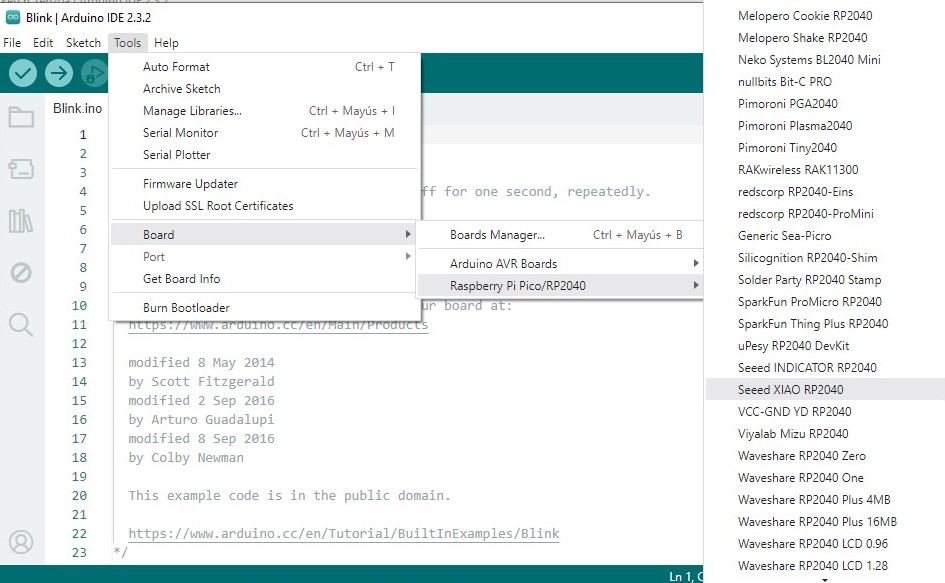 Image 18. To connect arduino with seeedstudio
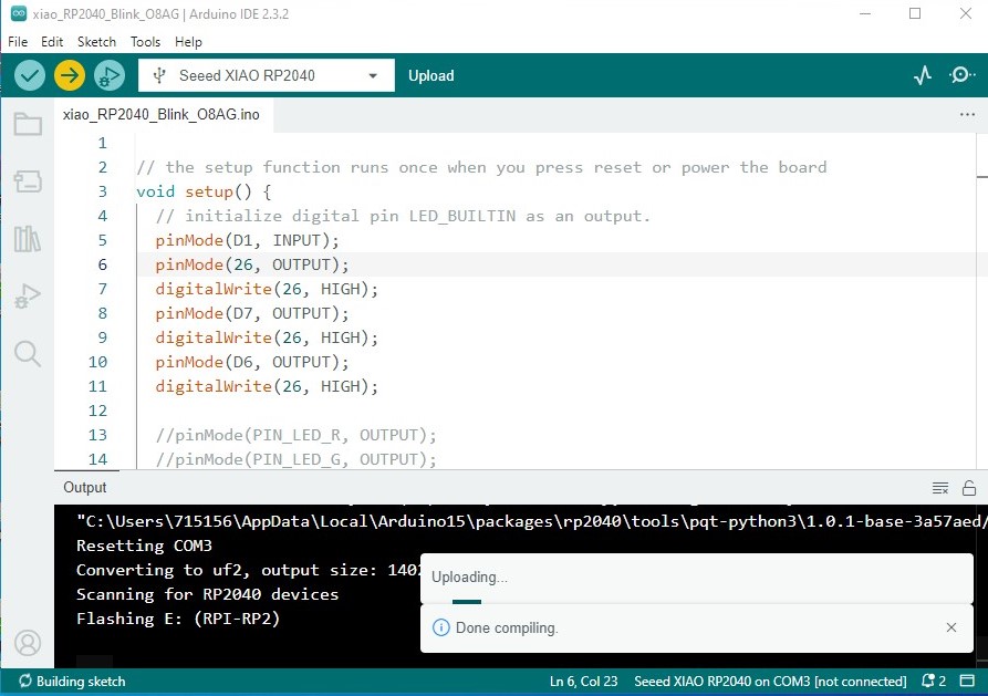 Image 19. To connect arduino with seeedstudio
Result of programming the on and off of LEDs with the button using arduino.
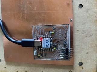
 Image 20. XIAO-RP2040 pinout diagram
Conclusion:
When you have a good system design, the connections are well made and the programming is appropriate, the desired result is obtained. I had never done soldering on devices, I had to practice with some "plates" before doing this activity.
It has been very satisfactory to be able to make the LED turn on and the button to work.