Electronic Design
It was a challenging week for me; for the first time, I applied my knowledge in engineering and fundamentals of electricity to design my PCB. The idea behind this design is to create a board for my final project that includes enough digital pins for a push button and a Neopixel strip, sufficient common grounds, and most importantly, to design a voltage regulator. I will power this board using two 3.7V batteries, resulting in 7.4V, but my microcontroller and the Neopixel strip only support 5V, so I need to step down the voltage.
GROUP ASSIGMENT
Components
| Product | Quantity |
|---|---|
| XIAOESP32S3 | 3 |
| Ceramic Capacitor 0805 10uF 16V CL21A106KOQNNNE | 6 |
| Battery Holder Batteries/td> | 3 |
| 18650 Battery 3.7V 2200mAh | 6 |
| Neopixel Strip WS2812 5050 RGB LED | 6 |
| L7805CV 5V 1.5A Regulator | 3 |
| Large Push Button 12mmx12mm | 3 |
XIAOESP32S3
The ESP32 is an excellent choice for my project of controlling Neopixels with a button due to its powerful dual-core processor, ample RAM and flash memory, and integration of Wi-Fi and Bluetooth. This allows it to handle intensive tasks and offer wireless connectivity without issues. Additionally, its compatibility with the Arduino IDE and support from a large community of developers make development and troubleshooting easier. It is an economical microcontroller, widely available, and with multiple GPIO pins, providing flexibility for future expansions. All these factors make the ESP32 not only suitable for this specific project but also a solid investment for future developments.
Pins
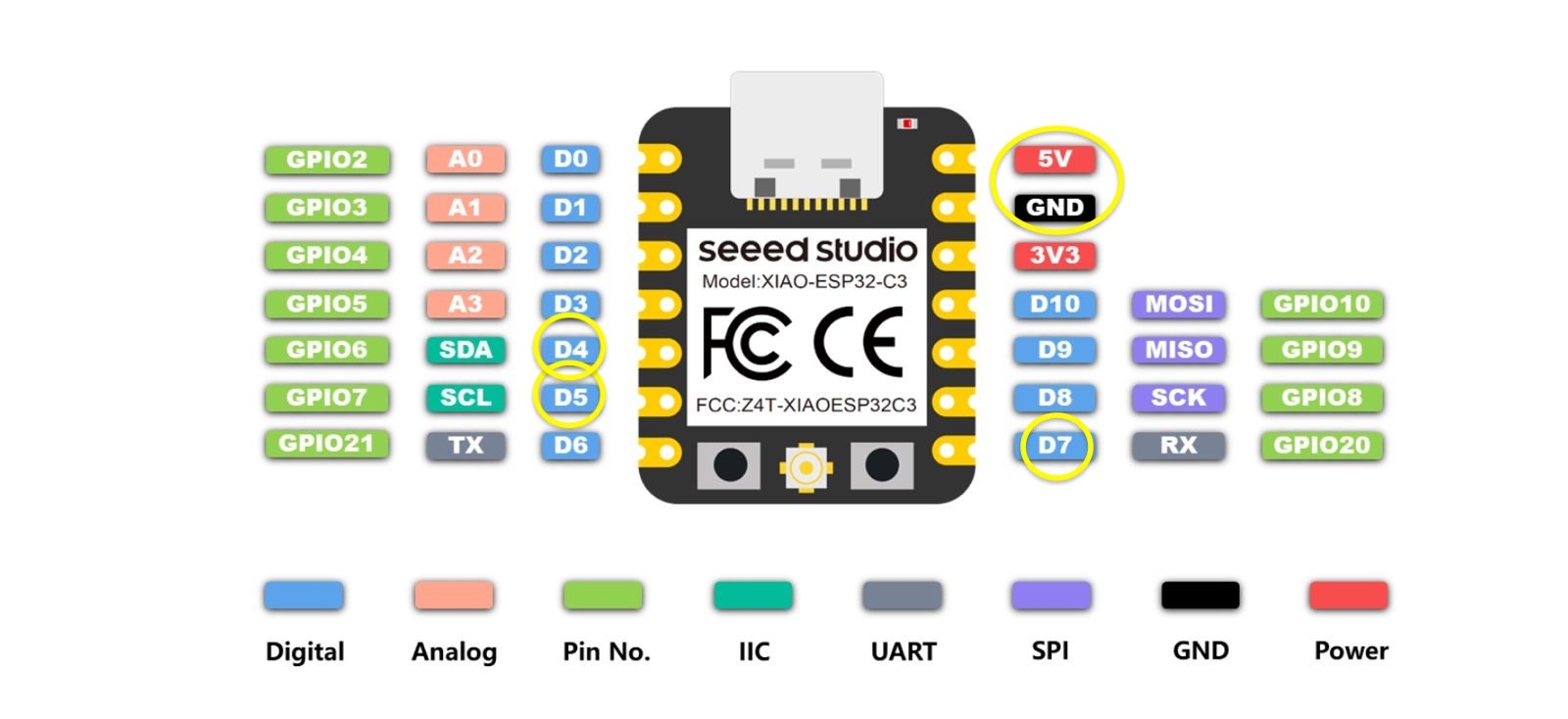
As it is a simple circuit, some of the pins of the XiaoESP32 will be used, which are as follows:
- 5V pin: will receive 5V power
- GND pin: ground connection for the circuits
- Pin D7: where the push button is connected
- Pin D4: digital pin
- Pin D5: connection for the Neopixel
EASYEDA
EasyEDA is great for designing circuits and PCBs because its interface is simple and has powerful tools. You can create schematics by dragging and dropping components, making the design process easy even if you are a beginner. Additionally, it has a large library of components and models to simulate how your designs will work before physically building them, which helps save time and avoid costly errors. With collaborative features, you can also share and work on projects efficiently as a team.

Below is the schematic of the circuit, with a 7.4V input voltage passing through the voltage regulator to step down to 5V, and then supplying power to both the microcontroller and the Neopixel strip.
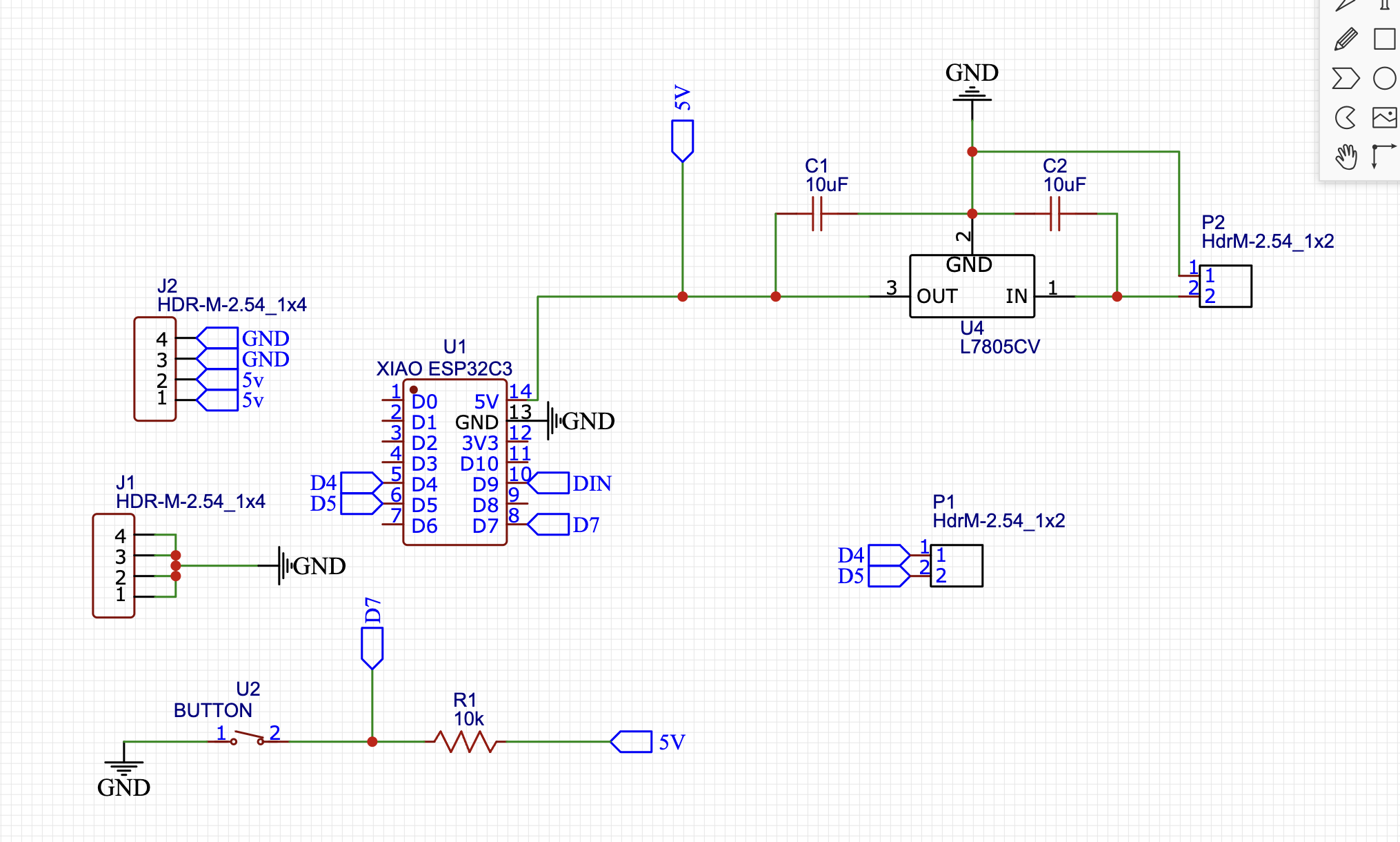
We will divide this circuit into three sections: Voltage Regulator, connection to XIAOESP32S3, and the push button circuit.
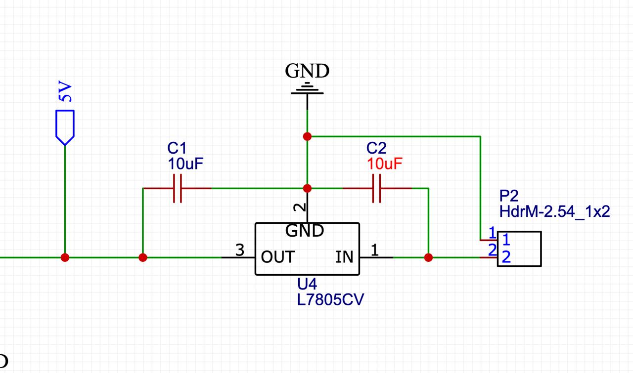
Voltage Regulator
By using two 7.4V batteries and the XiaoESP32 only accepting 5V, I had to use an L7805CV 5V 1.5A voltage regulator with two 0805 10uF ceramic capacitors, resulting in the following circuit:
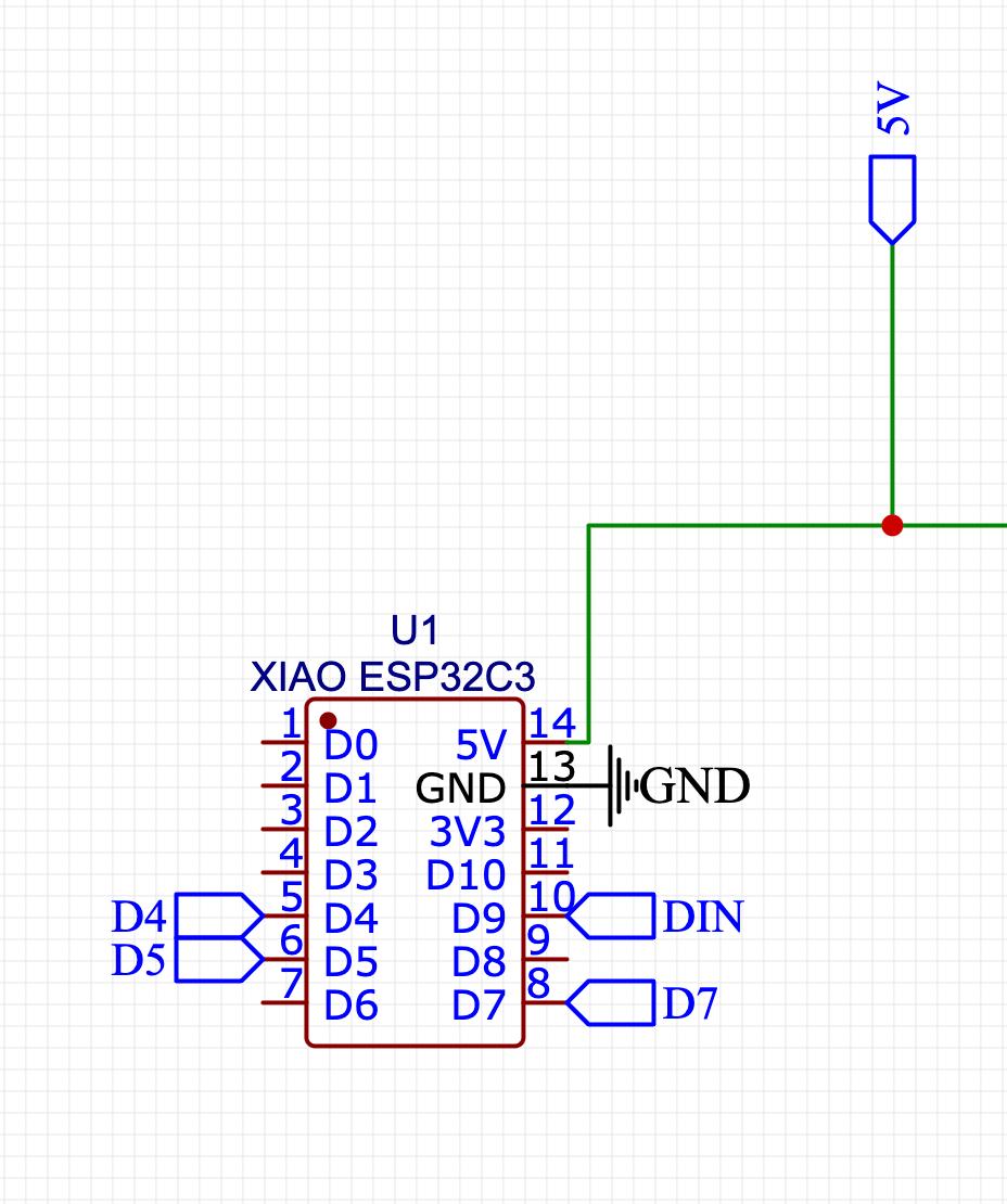
Connections to XIAOESP32S3
Once we have a 5V output voltage, we will proceed to connect it to the 5V input pin of the XiaoESP32. The XiaoESP32 has labels on the pins, and each label indicates the corresponding pin we will use.
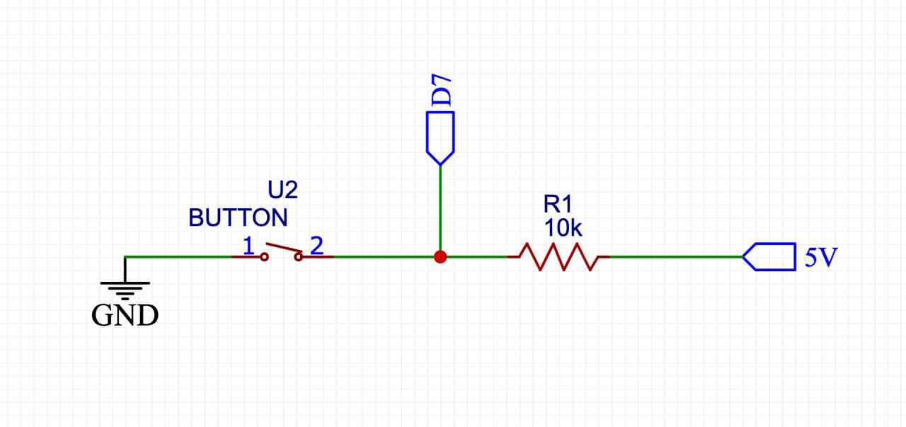
Push button
El push button está en configuración pull up (quiere decir que utiliza una resistencia de pull-up para mantener una entrada lógica en un estado alto (1 lógico) cuando el botón no está presionado.) Entonces cuando se presióne el button,la tira Led se apagará
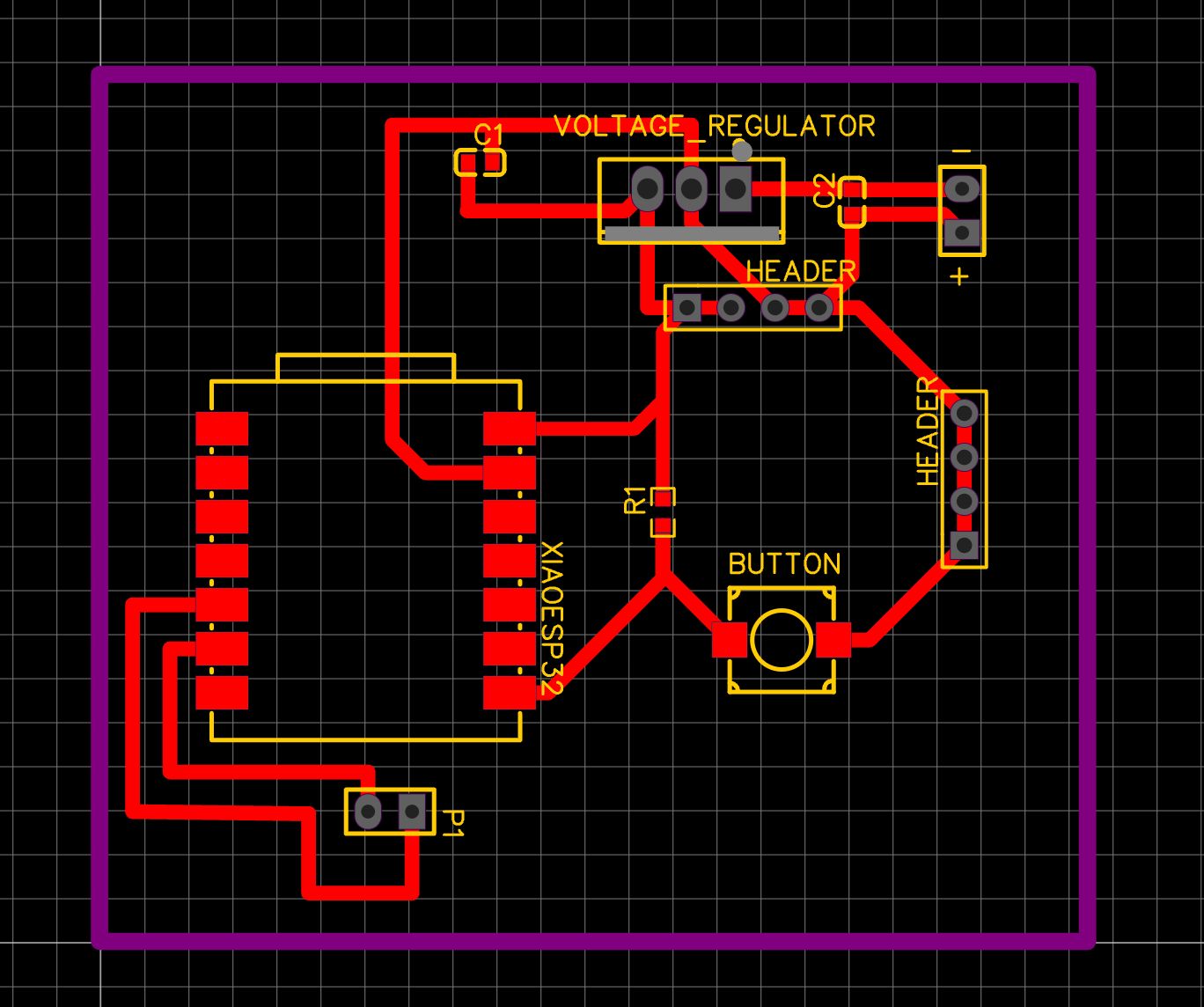
PCB Design
The plate must have a maximum size of 6cm x 6cm so I decided to make it 5cm x 5cm.
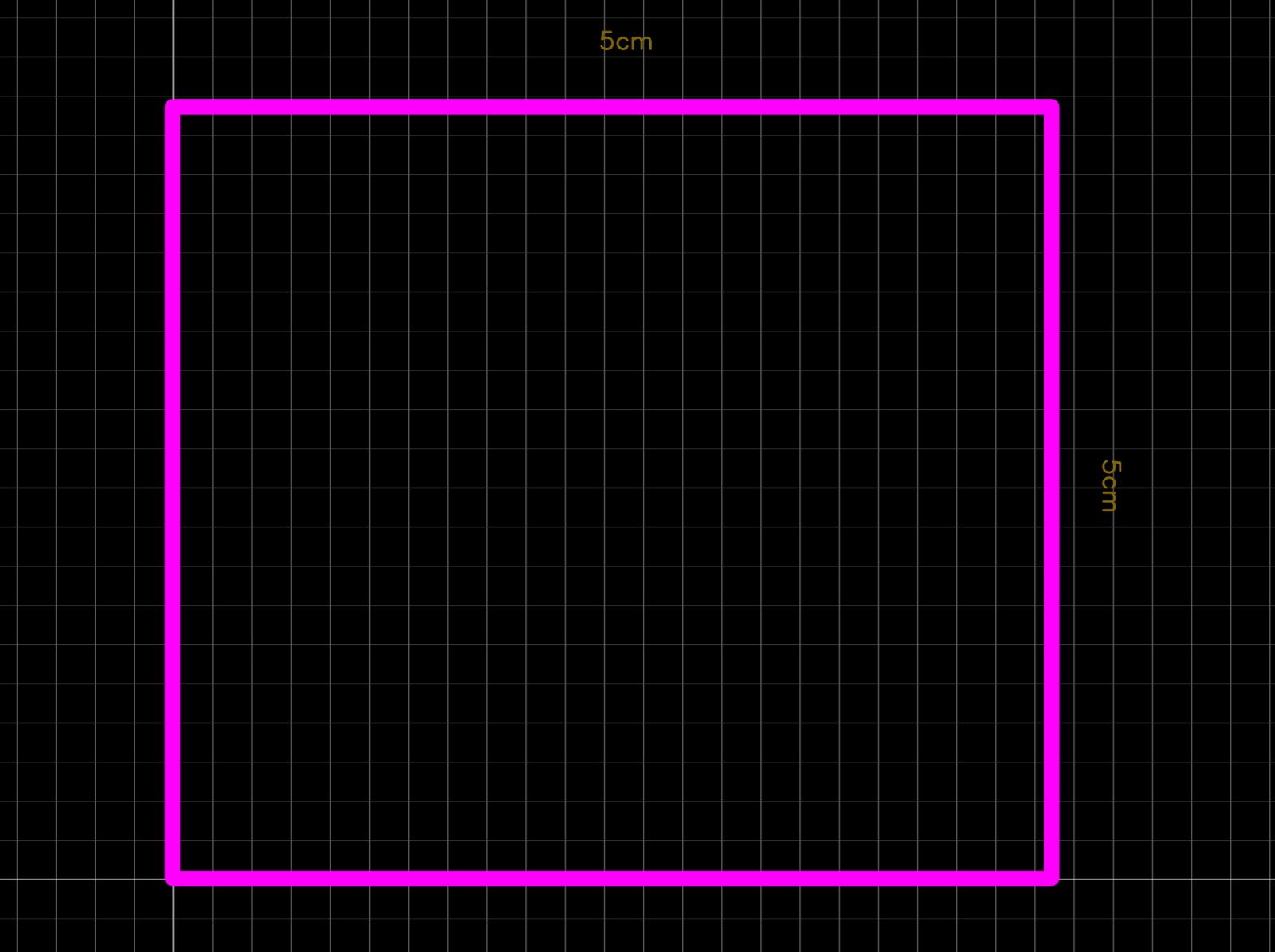
Once the frame is outlined, the components are inserted and arranged in the work area.
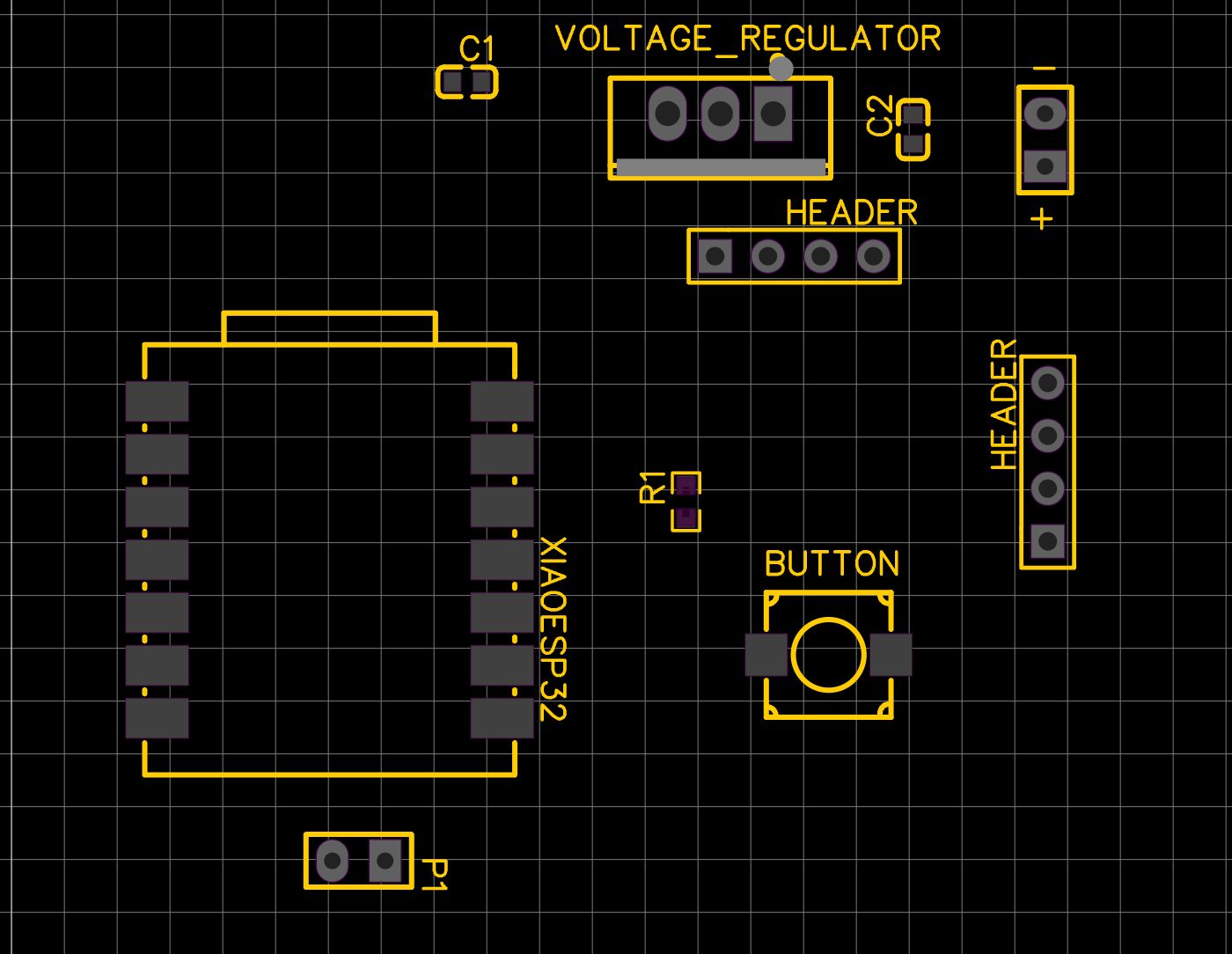
This is a difficult stage; tracers must be drawn connecting the components without the lines touching. Since the design is on one layer, if these lines cross, it could cause a design failure, resulting in a short circuit or a bridge.
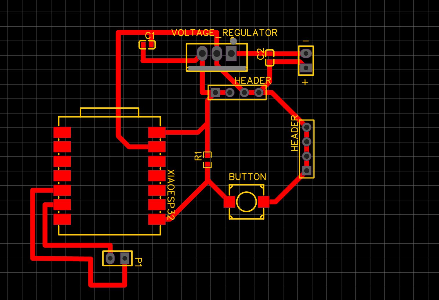
Final Design
After arranging and connecting, this is the final design result.
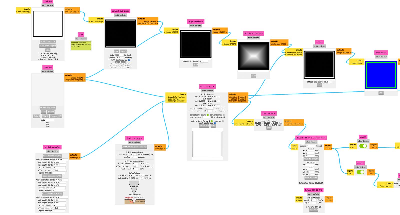
ModsProject
We will use the software from modsproject.com that we used earlier in week 04. We select our machine, which in this case is the Roland Monofab, and upload the file in SVG format.
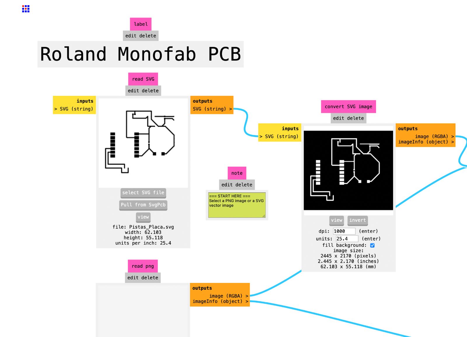
Then we press invert.
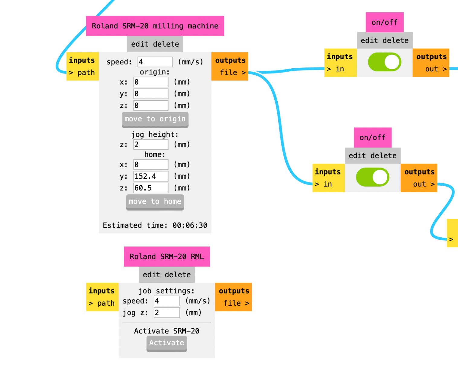
As the next step, we set the origin to 0, 0, 0 and check if the buttons are on; if not, we turn them on.
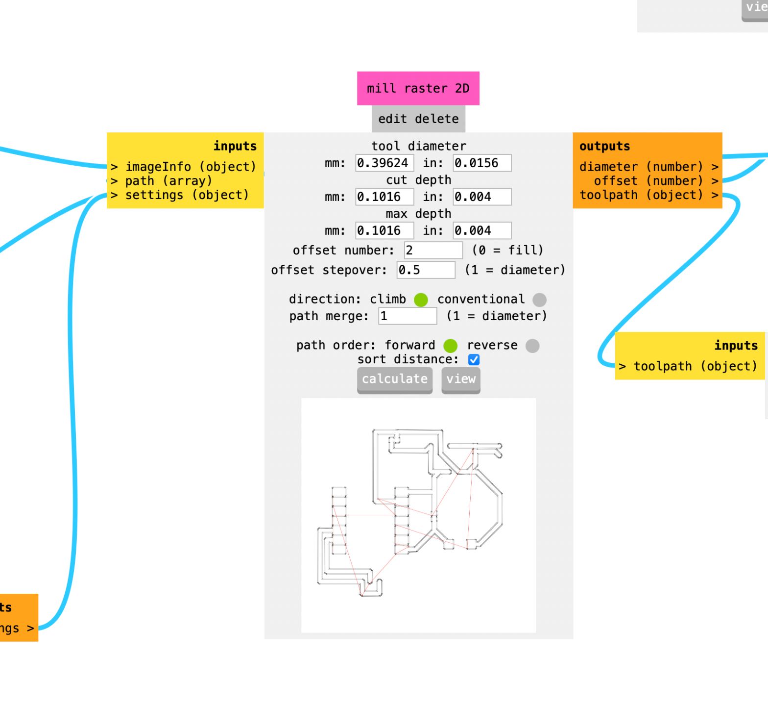
In this part, I changed the offset number to 2 and pressed calculate. Once we press it, the file will be downloaded in ".rml" format.
This is the configuration to cut the frame
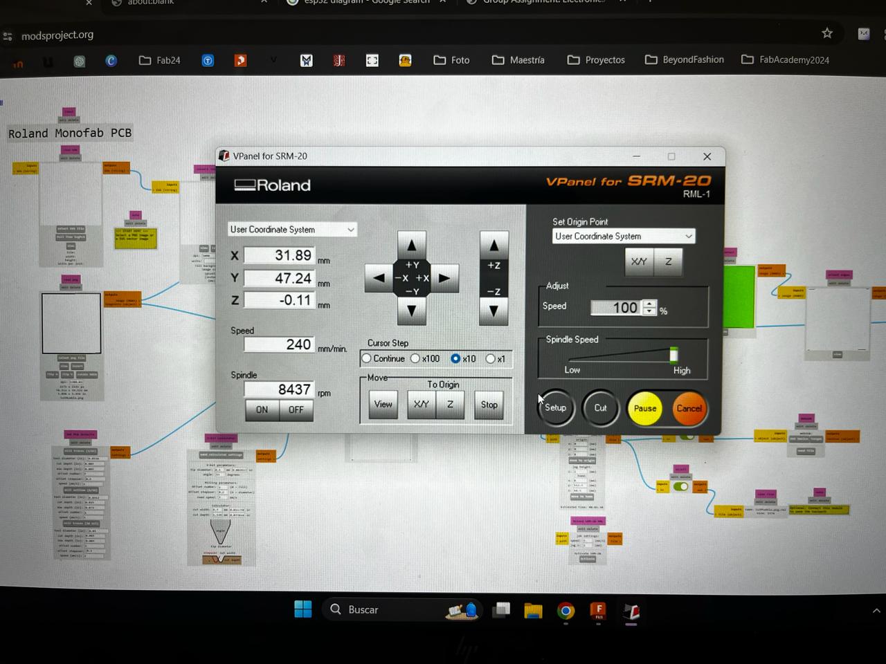
Milling Roland
This program help us to configurate the axies for the milling, we set up the origin at the bottom left
Nice! Once we set up the machine we need to use two tools.
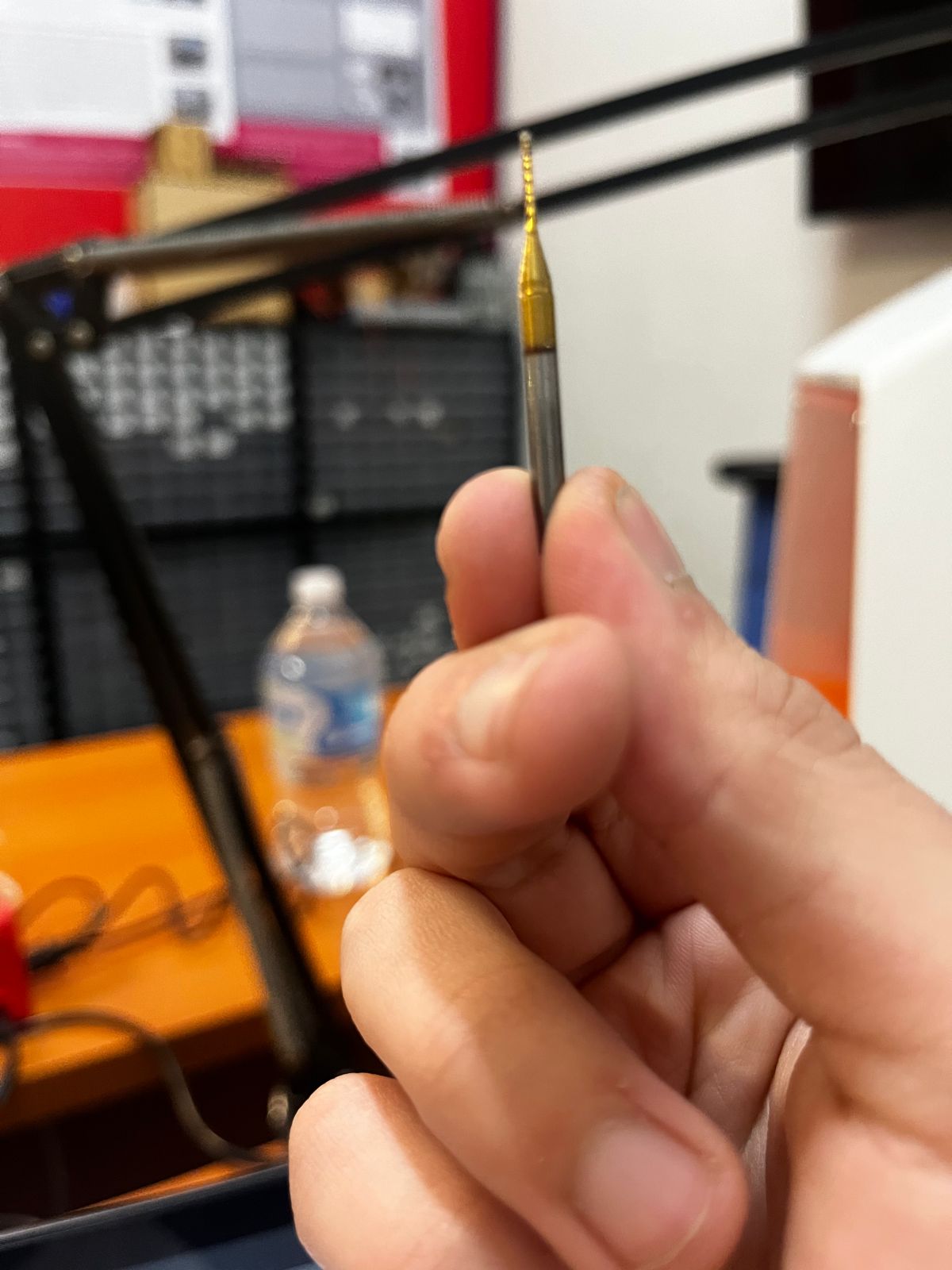
For engraving we're using a 15 degree V-bit
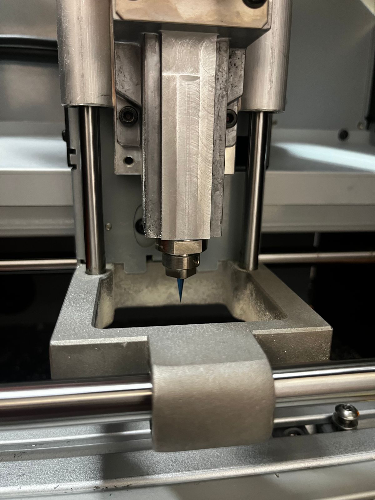
And for cutting we're using a 0.8 mm diameter two flute end Mill.
Once we press Cut in the VPanel it is going to start cutting the PCB
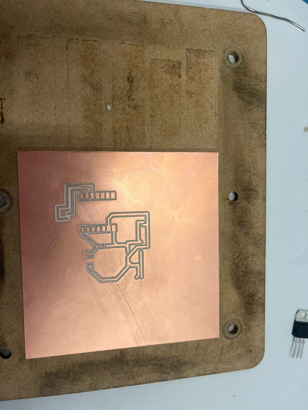
Then we change for cutting
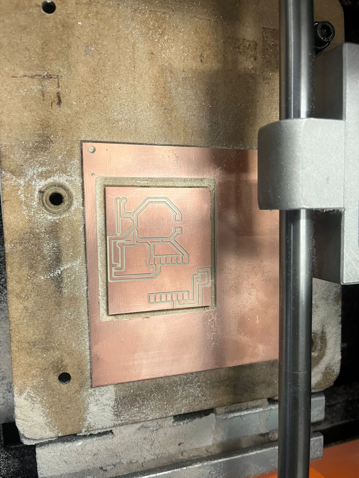
Once our board is cut, we will move on to soldering the components and then to programming.

Programming
This program uses an ESP32 microcontroller along with a NeoPixel strip controlled by pin D5 and a button connected to pin D7. At the beginning, serial communication is initialized, and the button is configured as an input with pull-up to detect its state. The NeoPixel strip is initialized to use the GRB protocol at a frequency of 800 KHz. In the main loop, the program continuously checks the button's state. If the button is pressed (low state), all NeoPixels are turned off using a loop that sets the color of each LED to black. On the other hand, if the button is not pressed (high state), the NeoPixels light up with a specific red color for each LED. Each change in the NeoPixels configuration is displayed using the pixels.show() method.
This program is ideal for projects where controlling a NeoPixel strip with a button is required, allowing for easy interactivity and lighting state control. The use of serial communication facilitates debugging and monitoring of the button's state, while the pull-up configuration ensures stable button behavior during use.
Final result
Once the program is loaded onto the ESP32 and the components are soldered, we will proceed to insert the batteries to check if the circuit works correctly.